Table of Contents
Advertisement
Quick Links
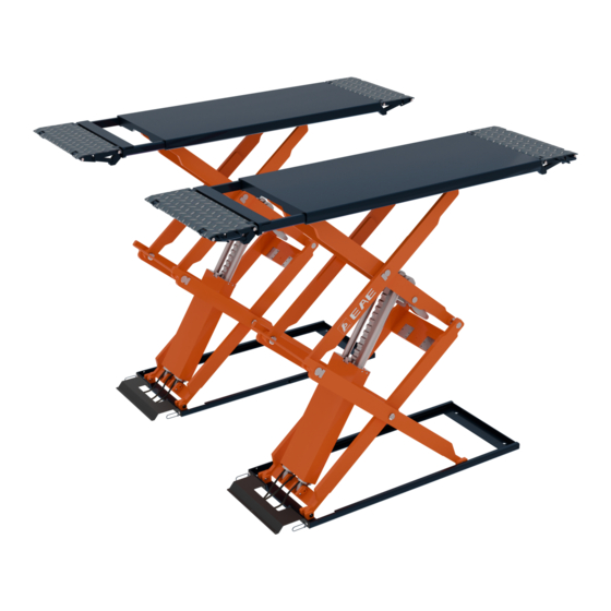
Model No. EE-6501
Installation, Operation
Short platform scissor lift
and Parts Manual
Low profile
Electrical Levelling
With synchronization protection
Lifting capacity: 3000KG
Distributed by
Please read this entire manual carefully and completely before installation or operation of the lift.
Date: 05/07/2021
Advertisement
Table of Contents

Related Manuals for EAE EE-6501


Summary of Contents for EAE EE-6501
- Page 1 Model No. EE-6501 Installation, Operation Short platform scissor lift and Parts Manual Low profile Electrical Levelling With synchronization protection Lifting capacity: 3000KG Distributed by Please read this entire manual carefully and completely before installation or operation of the lift. Date: 05/07/2021...
-
Page 2: Important Notes
Liability The liability of EAE is limit to the amount that the customer has actually paid for this product. This exclusion of liability does not apply to damages caused through willful misconduct or gross negligence on the part of EAE. -
Page 3: Table Of Contents
Installation, Operation and Parts Manual EE-6501 IMPORTANT NOTES ................................2 SAFETY NOTES ..................................4 1.1 Operation of lifting platforms ..............................4 1.2 Checking of the lifting platforms .............................. 4 1.3 Important safety notices ................................5 1.4 Warning labels ..................................6 1.5 Potential safety risks ................................. -
Page 4: Safety Notes
Installation, Operation and Parts Manual EE-6501 SAFETY NOTES 1.1 Operation of lifting platforms This lift is specially designed for lifting motor vehicles. Users are not allowed to use it for any other purposes. The applicable national regulations, laws and directives must be observed. -
Page 5: Important Safety Notices
Installation, Operation and Parts Manual EE-6501 A qualified person is somebody with the training and experience required to possess sufficient knowledge of lifting platforms and who is sufficiently familiar with the pertinent national regulations, accident prevention regulations and generally acknowledged rules of engineering to be able to assess the safe operating condition of lifting platforms. -
Page 6: Warning Labels
Installation, Operation and Parts Manual EE-6501 1.4 Warning labels All safety warning labels are clearly depicted on the lift to ensure that the operator is aware of and avoid the dangers of using the lift in an incorrect manner. The labels must be kept clean and they have to be replaced if detached or damaged. Please read carefully the meaning... -
Page 7: Potential Safety Risks
Installation, Operation and Parts Manual EE-6501 1.5 Potential safety risks 1.5.1 Mains voltage nsulation damage and other faults may result in accessible components being live Safety measures: Only ever use the power cord provided or a tested power cord. -
Page 8: Packing, Storage And Transportation
Installation, Operation and Parts Manual EE-6501 PACKING, STORAGE AND TRANSPORTATION Packing, lifting, handling, transporting operations must be performed only by experienced personnel with appropriate knowledge of the lift and after reading this manual. 2.1 The lift was dismantled into the following 2 parts for transportation... -
Page 9: Product Descriptions
Installation, Operation and Parts Manual EE-6501 PRODUCT DESCRIPTIONS 3.1 General descriptions This is chassis supporting vehicle lift for road vehicles. Being designed with pretty lower profile(110mm) when at its lowest position, users could have it installed with great convenience. Its platform extension deign not only can be used as a ramp, but also can serve as an extended part of the platform for much longer vehicles. -
Page 10: Dimensions
Installation, Operation and Parts Manual EE-6501 3.3 Dimensions... -
Page 11: Safety Devices Descriptions
Installation, Operation and Parts Manual EE-6501 3.4 Safety devices descriptions POS. Safety device Function 24V operation voltage Safety voltage for operators. Ensure the lifting platform stop rising at rated maximum height above the Max height limit switch ground. The lifting platforms automatically stop lowering at a safe height above the ground. -
Page 12: Technical Data
Installation, Operation and Parts Manual EE-6501 3.5 Technical data Rated load capacity 3000kg Full rise height 1850mm Full lowered height 110mm Full rise time with load ≤60s Full lowering time with load ≤40s Hydraulic pressure 24MPa Pneumatic pressure 6-8bar Oil tank volume INSTALLATION INSTRUCTIONS 4.1 Preparations before installation... - Page 13 Installation, Operation and Parts Manual EE-6501 Surface mounting The area enclosed by the dash line (2300mm*2500mm) shall have a minimum thickness of 150mm.
- Page 14 Installation, Operation and Parts Manual EE-6501 Recessed mounting...
- Page 15 Control cabinet package Name EE-6501.E control cabinet Rubber pick up pad Expansion bolt Pneumatic hose...
-
Page 16: Installation Attentions
Installation, Operation and Parts Manual EE-6501 4.2 Installation attentions 4.2.1 Joints of oil hose and wiring must be firmly connected in order to avoid leakage of oil hose and looseness of electrical wires. 4.2.2 All bolts should be firmly screwed up. - Page 17 Installation, Operation and Parts Manual EE-6501 Step 5: Connect the electrical system. Requirements for power supply cable of the installation site: at least 2.5mm wire core for 3Ph power and 4.0mm wire core for 1Ph power. Refer to Annex 1 when fix the electrical system.
- Page 18 Installation, Operation and Parts Manual EE-6501 Set the pneumatic pressure between 6-8 bars. Push upward the button indicated in the following fig and turn the button until the hand of the pressure meter points to the NUMBER ”6” . Push the button down thereafter.
- Page 19 Installation, Operation and Parts Manual EE-6501 5. Turn the switch to the leveling mode , when both platforms lower to the lowest position. 6. Keep the switch under the levelling mode, push DOWN I or DOWN II to have the lower platform raised a bit and push the UP button to lower both platforms to the lowest position.
-
Page 20: Items To Be Checked After Installation
Installation, Operation and Parts Manual EE-6501 4.4 Items to be checked after installation. Check items Screw torque of expansion bolts : 60-80N•m; Rising speed ≥20mm/s; Noise with rated load ≤75dB; Grounding resistance: not bigger than 4Ω; Height difference of the two platform ≤5mm;... -
Page 21: Operation Instructions
Installation, Operation and Parts Manual EE-6501 5.2 Operation instructions Pos. Name Function Alarm buzzer Safety warning UP button Control the rising movement DOWN I button Control the lowering movement DOWN II button Control the lowering movement (for lowering safety ) -
Page 22: Operation Instructions
Installation, Operation and Parts Manual EE-6501 5.4 Operation instructions To avoid personal injury and/or property damage, permit only trained personnel to operate the lift. After reviewing these instructions, get familiar with lift controls by running the lift t hrough a few cycles before loading vehicle on lift. -
Page 23: Emergency Lowering
Installation, Operation and Parts Manual EE-6501 5.5 Emergency lowering Emergency situation means: 1. Electricity power failure 2. Failure on equipment itself Suitable condition: Compressed air is available. Normally, in case of sudden electricity power failure, the compressed air remained can still make the pneumatic system of the lift work. -
Page 24: Trouble Shooting
Installation, Operation and Parts Manual EE-6501 TROUBLE SHOOTING ATTENTION: If the trouble could not be fixed by yourself, please do not hesitate to contact us for help .We will offer our service at the earliest time we can. By the way, your troubles will be judged and solved much faster if you could provide us more details or pictures of the trouble. -
Page 25: Maintenance
Installation, Operation and Parts Manual EE-6501 MAINTENANCE Easy and low cost routine maintenance can ensure the lift work normally and safely. Following are requirements for routine maintenance. Follow the below routine maintenance schedule with reference to the actual working condition and frequency of your lift. - Page 26 Installation, Operation and Parts Manual EE-6501 Components Methods Period Pneumatic hoses and connectors Inspect to ensure no leakage before using the lift. Every day Check if both mechanical catches can engage and Mechanical safety catch disengage effectively and synchronously by pushing Every day control buttons.
-
Page 27: Annex 1, Wiring Diagrams And Parts List
Installation, Operation and Parts Manual EE-6501 Annex 1, Wiring diagrams and parts list... - Page 28 Installation, Operation and Parts Manual EE-6501...
- Page 29 Installation, Operation and Parts Manual EE-6501 SQ1: Max height limit switch SQ2: Safe descending limit switch SQ3: Photoelectric switch YA1: Pneumatic solenoid valve YV1: Solenoid unloading valve YV3: Levelling solenoid valve 1 YV4: Levelling solenoid valve 2...
- Page 30 Installation, Operation and Parts Manual EE-6501 Pos. CODE Name 320101023 Transformer (380V) 320101024 Transformer (400V) 320101025 Transformer (415V) 320101020 Transformer (220V) 320101021 Transformer (230V) 320101022 Transformer (240V) Motor SA1;SA2 320303019 Selection switch 320304001 Power switch 320306006 Photoelectric switch SQ1;SQ2 320306012...
-
Page 31: Annex 2, Hydraulic Diagrams And Parts List
Installation, Operation and Parts Manual EE-6501 Annex 2, Hydraulic diagrams and parts list 1. Oil tank 2. Filter 3. Gear pump 4. Coupling 5. Motor 6. Hydraulic block 7. Cushion valve 8. Overflow valve 9. Single way valve 10. Solenoid unloading valve 11. - Page 32 Installation, Operation and Parts Manual EE-6501 Pos. CODE Description Specification Power unit 3.5kW 624001266 Oil hose L=5800 624001876 L=4900 Oil hose 624002047 Oil hose L=4300 624001221 L=950 Oil hose 624001129 L=1750 Oil hose 624001005 L=230 Oil hose 410210181 6603B-A9-B7 Three way connector...
- Page 33 Installation, Operation and Parts Manual EE-6501 Pos. CODE Name Specification 330405001 Oil tank...
- Page 34 Installation, Operation and Parts Manual EE-6501 Pos. CODE Name Specification 201102002 M5*10 Hex head full swivel screw 202109064 M6*3 Hex socket cylinder head screw 207103025 G1/4 Composite washer 310101010 G1/4---G1/4 Shifting connector 330101008 YF-06 Hydraulic block 320201001 220V-2.2KW-1PH-50HZ-2P Motor Motor 320201002 230V-2.2KW -1PH-50HZ-2P...
-
Page 35: Annex 3, Pneumatic Diagrams And Parts List
Installation, Operation and Parts Manual EE-6501 Annex 3, Pneumatic diagrams and parts list Pos. CODE Name Specification 321004006 AFC2000-M AFC Air filter combination 310101015 KLC8-02 Pneumatic connector 123010101 Air hose 310103010 Match with M6 air hose Three way connector 310201002... -
Page 36: Annex 4, Mechanically Exploded Drawings And Parts List
Installation, Operation and Parts Manual EE-6501 Annex 4, Mechanically exploded drawings and parts list Pos. CODE Name Specification 614019501 Base frame 6501.B-A1-B1 410192331 Limit switch holding plate 65012-8 202101027 Cross socket cap head screw M6*8 320306010 Proximity sensor Y18-Z-PK4 202101040... - Page 37 Installation, Operation and Parts Manual EE-6501...
- Page 38 Installation, Operation and Parts Manual EE-6501 Pos. CODE Name Specification 420190190 UP slider 65012-A2-B17 410195061 UP rotation shaft 65012-A2-B15 204301009 Circlip 614019502 Arm B 65012-A2-B1 208106002 Oil cup M8 410195021C Joint shaft C 65012-A2-B6 205101017 Bearing SF-2X 205101060 Bearing SF-2X...
- Page 39 Installation, Operation and Parts Manual EE-6501 Pos. CODE Name Specification 410190151 Oil cylinder connection B 6501-A4-B1 410190111 Oil cylinder roller wheel 6501-A4-B12 410195131C Oil cylinder rotation shaft 6501V2-A3-B1 204301014 Circlip 420190230 Rubber pad 38*120*100 320306006 Infrared sensor HG-M18NPN 202101007 Cross socket cap head screw...
- Page 40 Installation, Operation and Parts Manual EE-6501 Pos. CODE Name Specification 410195181B Shaft of the lifting platform 65012-A5-B2 614019507 Supporting rod 65012-A5-B1-C6 204301004 Circlip 420180010 Small roller wheel MR30-A22-B5 614019506 Ramp A 65012-A5-B1 410195071 Shaft of the ramp 65012-A5-B1-C4 614019509 Ramp B 65012-A5-B4 Pos.
Need help?
Do you have a question about the EE-6501 and is the answer not in the manual?
Questions and answers