Table of Contents
Advertisement
Advertisement
Table of Contents

Related Manuals for EAE EE-6603BWF


Summary of Contents for EAE EE-6603BWF
- Page 1 Installation, Operation and Parts Manual Model No. EE-6603BWF Long platform scissor lift, In-ground Installation Manual Levelling Lifting Capacity 4200KG/ 5000KG Please read this entire manual carefully and completely before installation or operation of the lift. 2017.07.27- 540104106...
-
Page 2: Important Notes
Liability The liability of EAE is limit to the amount that the customer has actually paid for this product. This exclusion of liability does not apply to damages caused through willful misconduct or gross negligence on the part of EAE. -
Page 3: Table Of Contents
Installation, Operation and Parts Manual EE-6603BWF IMPORTANT NOTES .............................. 2 SAFETY NOTES ..............................4 1.1 Operation of lifting platforms ............................4 1.2 Checking of the lifting platforms ........................... 4 1.3 Important safety notices ............................... 5 1.4 Warning labels ................................6 1.5 Potential safety risks .............................. -
Page 4: Safety Notes
Installation, Operation and Parts Manual EE-6603BWF SAFETY NOTES 1.1 Operation of lifting platforms This lift is specially designed for lifting motor vehicles. Users are not allowed to use it for any other purposes. The applicable national regulations, laws and directives must be observed. -
Page 5: Important Safety Notices
Installation, Operation and Parts Manual EE-6603BWF sufficiently familiar with the pertinent national work safety regulations, accident prevention regulations and generally acknowledged rules of engineering to be able to check and give an expert option on lifting platforms. 1.3 Important safety notices 1.3.1 Recommend for indoor use only. -
Page 6: Warning Labels
Installation, Operation and Parts Manual EE-6603BWF 1.4 Warning labels All safety warning labels are clearly depicted on the lift to ensure that the operator is aware of and avoid the dangers of using the lift in an incorrect manner. The labels must be kept clean and they have to be replaced if detached or damaged. Please read carefully the... -
Page 7: Potential Safety Risks
Installation, Operation and Parts Manual EE-6603BWF 1.5 Potential safety risks 1.5.1 Mains voltage nsulation damage and other faults may result in accessible components being live. Safety measures: Only ever use the power cord provided or a tested power cord. -
Page 8: Packing, Storage And Transportation
Installation, Operation and Parts Manual EE-6603BWF PACKING, STORAGE AND TRANSPORTATION Packing, lifting, handling, transporting operations must be performed only by experienced personnel with appropriate knowledge of the lift and after reading this manual. 2.1 The lift was dismantled into 3 parts for transportation... -
Page 9: Product Descriptions
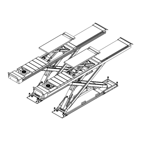
Installation, Operation and Parts Manual EE-6603BWF PRODUCT DESCRIPTIONS 3.1 General descriptions This model is recessed mounted and is mainly composed by two lifting platforms and a set of power unit. The gear pump works making oil in the pump will push upwards the pistons of oil cylinders. Thus, scissor brackets of the lift rise accordingly. In case of hydraulic failure, the mechanical safety locking unit ensures no sudden fall of lifting platforms. -
Page 10: Dimensions
Installation, Operation and Parts Manual EE-6603BWF 3.3 Dimensions Specification *.42L 4200 4442 1320 *.48L 4800 5042 1520 1370 *.51L 5100 5342 1520 1570... -
Page 11: Technical Data
Installation, Operation and Parts Manual EE-6603BWF 3.4 Technical data Specification *.42L.42T *.48L.42T/*.48L.50T *.51L .50T Rated capacity of the main lift 4200KG 4200KG/5000KG 5000KG Applicable wheel track of the main lift 1100~1800mm 1100~1800mm 1100~1800mm ≤4000mm ≤4600mm ≤4900mm Applicable wheel base of the main lift... -
Page 12: Installation Attentions
Installation, Operation and Parts Manual EE-6603BWF 4.1.4 Tools and equipment for installation Tool name Specification Electrical drill With D16 and D18 drill bit. Open spanner D17-19mm Adjustable spanner bigger than D30mm Cross socket screw driver Quick spanner handle adapter/ Ratchet... -
Page 13: General Installation Steps
Installation, Operation and Parts Manual EE-6603BWF 4.3 General installation steps Step 1: Dismantle the package and place lifting platforms into recessed pits with a forklift and lifting straps. Raise the platform by using a forklift and 2 lifting straps until the mechanical lock is engaged. Dismantle the bolts that fix the platform and its wooden package and then hoist the platform onto the expected installation site. -
Page 14: Items To Be Checked After Installation
Installation, Operation and Parts Manual EE-6603BWF 5) Repeat the above levelling steps if synchronization is not achieved. Level the wheel free lift 1) Turn the selection switch on the control panel to the” wheel free lift” and the selection switch in the control cabinet to “levelling”mode. -
Page 15: Operation Instructions
Installation, Operation and Parts Manual EE-6603BWF OPERATION INSTRUCTIONS 5.1 Precautions 5.1.1 Check all the joints of oil hose. Only when there is no leakage, the lift can start work. 5.1.2 The lift, if its safety device malfunctions, shall not be used. -
Page 16: Working Flow Chart
Installation, Operation and Parts Manual EE-6603BWF 5.3 Working flow chart 5.4 Operation instructions The lift must be only used in a static position for lifting and lowering vehicles. Only use this lift on a surface that is stable and capable of sustaining the load. Do not install the lift on any asphalt sur face. - Page 17 Installation, Operation and Parts Manual EE-6603BWF Using the wheel free lift. Lifting capacity: 3500KG Raise the wheel free lift 1. Turn the Selection switch on the control panel to “wheel free lift”. 2. Place rubber pads under the pick-up positions of vehicle. When it is necessary to use the platform extensions, push “UP” button to raise platforms of the jack a bit over the platforms of main lift and pull out the extensions.
-
Page 18: Trouble Shooting
Installation, Operation and Parts Manual EE-6603BWF TROUBLE SHOOTING ATTENTION: If the trouble could not be fixed by yourself, please do not hesitate to contact us for help .We will offer our service at the earliest time we can. By the way, your troubles will be judged and solved much faster if you could provide us more details or pictures of the trouble. -
Page 19: Maintenance
Installation, Operation and Parts Manual EE-6603BWF MAINTENANCE Easy and low cost routine maintenance can ensure the lift work normally and safely. Follow the below routine maintenance schedule with reference to the actual working condition and frequency of your lift. Lubricate with No.1 lithium base grease. - Page 20 Installation, Operation and Parts Manual EE-6603BWF Components Methods Period Check the synchronization of both lifting platforms. Lifting platform Ensure both platforms ascend and descend Every day synchronously. Open the control unit, inspect the wire terminals and Terminals in the control unit Every 3 months screw firmly if any terminals become loose.
-
Page 21: Annex 1, Floor Plan For Recessed Installation
Installation, Operation and Parts Manual EE-6603BWF Annex 1, Floor plan for recessed installation 1. Indoor installation only. There must be a clearance of at least 1 meter between the lifting platform and fixed elements (e.g. wall) in all lifting positions. There must also be sufficient space for driving vehicles on and off. - Page 22 Installation, Operation and Parts Manual EE-6603BWF 48L: 51L:...
- Page 23 Installation, Operation and Parts Manual EE-6603BWF 42LC: 48LC:...
- Page 24 Installation, Operation and Parts Manual EE-6603BWF 51LC:...
-
Page 25: Annex 2, Electrical Diagrams And Parts List
Installation, Operation and Parts Manual EE-6603BWF Annex 2, Electrical diagrams and parts list... - Page 26 Installation, Operation and Parts Manual EE-6603BWF...
- Page 27 Installation, Operation and Parts Manual EE-6603BWF SQ1: Height limit switch of the main lift SQ2: Height limit switch of the wheel free lift SQ3: Height limit switch for safe lowering YA: Pneumatic valve for the main lift YV1: Solenoid unloading valve...
- Page 28 Installation, Operation and Parts Manual EE-6603BWF Pos. CODE Name Specification 320101032 Transformer(220V) JBK3(JBK5)-100VA 220V-24V 320101033 Transformer(230V) JBK3(JBK5)-100VA 230V-24V 320101034 Transformer(240V) JBK3(JBK5)-100VA 240V-24V 320101035 Transformer (380V) JBK3(JBK5)-100VA 380V-24V 320101036 Transformer (400V) JBK3(JBK5)-100VA 400V-24V 320101037 Transformer (415V) JBK3(JBK5)-100VA 415V-24V SQ1,SQ2 320301003 Limit switch...
- Page 29 Installation, Operation and Parts Manual EE-6603BWF Pos. CODE Name Specification 320503002 Ground terminals 320505006 Wire terminal VK-5N(UK-5N) 320505011 Retaining chip LT-2.5 320601002 Relay HH54P-L/AC24V(MY4NJ) KA2,KA3 320601001 Relay HH54P-L/DC24V(MY4NJ) 320601011 Relay holder PYF-14A-E 320601018 Relay feet fixer 320602009 Integrated time relay...
-
Page 30: Annex 3, Hydraulic Diagrams And Parts List
Installation, Operation and Parts Manual EE-6603BWF Annex 3, Hydraulic diagrams and parts list Oil tank Solenoid unloading valve Oil sucking filter Flow control valve Gear pump Oil tank cover Coupling Leveling valve Motor Ball valve Hydraulic block Main cylinder of the main lift... - Page 31 Installation, Operation and Parts Manual EE-6603BWF...
- Page 32 Installation, Operation and Parts Manual EE-6603BWF Pos. CODE Name Specification Hydraulic power unit 2.2kW/3.0kW/3.5kW Composite washer 207103025 G1/4 Straight connector 310101010 G1/4---G1/4 inside swivel Rubber oil hose 624001152 Φ8,L=6000mm Straight connector 410210191 6603B-A9-B8 Main cylinder of the wheel free lift...
- Page 33 Installation, Operation and Parts Manual EE-6603BWF Pos. CODE Name Specification Straight connector 310101010 G1/4---G1/4 Steel oil tank 330405027 Straight connector 310101025 G1/4--G1/4 Hex socket cylinder head screw 202109064 M6*30 Composite washer 207103025 13.7*20.00*1.50(BS224)
- Page 34 Installation, Operation and Parts Manual EE-6603BWF Pos. CODE Name Specification 320201001 Motor 220V-2.2KW -1PH-50HZ-2P 320201002 Motor 230V-2.2KW-1PH-50HZ-2P 320201003 Motor 240V-2.2KW -1PH-50HZ-2P 320201004 Motor 380V-2.2KW -3PH-50HZ-2P 320201005 Motor 400V-2.2KW --3PH-50HZ-2P Motor 320204016 380V-3.0KW -3PH-50HZ-2P Motor 320203005 400V/3.5KW -3PH-50HZ-2P Motor 320203001 380V-3.5KW -3PH-50HZ-2P...
-
Page 35: Annex 4, Pneumatic Connections And Parts List
Installation, Operation and Parts Manual EE-6603BWF Annex 4, Pneumatic connections and parts list Pos. CODE Name Specification AFC Air filter combination 321004006 AFC2000 Pneumatic connector 310101015 KLC8-02 Air hose 123010201 Three way pneumatic connector 310103006 KLE-8 Silencer 310201003 SLM01 R1/8 (M8) -
Page 36: Annex 5, Mechanically Exploded Drawings And Parts List
Installation, Operation and Parts Manual EE-6603BWF Annex 5, Mechanically exploded drawings and parts list Pos. CODE Name Specification 410211500 Bracket A for limit switch 6603B-A7-B11 202109008 Hex socket cylinder head screw M5*12 320301003 Limit switch D4MC-5020 614021032 Base A 6603B-A7-B9... - Page 37 Installation, Operation and Parts Manual EE-6603BWF Pos. CODE Name Specification 202101002 Cross socket cap head screw M3*15 410210171 Guide track 6603B-A7-B7 202103024 Cross sunken head bolt M10*25 410210161 Cushion head 6603B-A7-B1-C3 410210151 Cushion holder 6603B-A7-B1-C1 410211390 Spring 6603B-A7-B1-C2 203101009 208103001...
- Page 38 Installation, Operation and Parts Manual EE-6603BWF Pos. CODE Name Specification 310201003 Muffler SLM01 R1/8 (M8) 420210050 UP wheel of the main lift 6603B-A5-B4 410210131 UP shaft 6603B-A5-B12 204301011 Circlip D30 GB/T894.2-1986 205101018 Bearing 3025 SF-1 612021003B Rotation shaft of the main lift...
- Page 39 Installation, Operation and Parts Manual EE-6603BWF Pos. CODE Name Specification 615021005 Assistant cylinder of jack 6603B-A3-B2 410210091 Down shaft 6603B-A3-B7 410212090 Three way connector 6603B-A3-B8 410210051C Shaft B 6603B-A2-B7 205101005 Bearing 2022 SF-1 410210041B Down wheel 6603B-A2-B6 410210031C Shaft A...
Need help?
Do you have a question about the EE-6603BWF and is the answer not in the manual?
Questions and answers