Table of Contents
Advertisement
Quick Links
Advertisement
Table of Contents

Subscribe to Our Youtube Channel
Related Manuals for sauter ASV3


Summary of Contents for sauter ASV3
- Page 1 MANUAL SAUTER ASV3 Page 1 of 45...
- Page 2 Page 2 of 45...
-
Page 3: Table Of Contents
1 Contents ABOUT CONTROLLERS ..................5 About Controllers ............................5 Specifications .............................. 5 2.2.1 Analog Inputs ..........................5 2.2.2 Analog Outputs ..........................5 2.2.3 Digital Outputs ..........................5 2.2.4 Communications to BACnet MS/TP ................... 6 2.2.5 Air Flow Sensor Features ......................6 2.2.6 Memory ............................ - Page 4 Configuring the VAV Terminal Box Options ....................18 Configuring the Airflow Set-points ......................19 Configuring the Airflow Testing and Calibration ..................20 4.10 Configuring the Damper Position ......................21 4.11 Calibrating the Sensors ........................... 22 4.12 Exiting Configuration Mode ........................23 4.13 Configuring the Instance ID ........................
-
Page 5: About Controllers
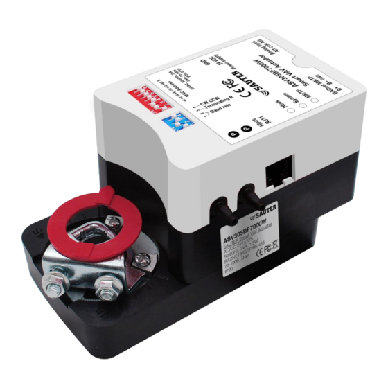
2 ABOUT CONTROLLERS 2.1 About Controllers ASV305BF7XXXW smart VAV actuators provide high-performance DDC (direct digital control) of pressure-independent, VAV (variable-air-volume) functions are designed and produced for extended functionalities in HVAC systems, VAV and laboratory applications. The controllers’ features are simple to set up yet comprehensive what the function to use. We are menu-driven and 3 setup choices when using the ASV305BF7XXXW VAV actuator. -
Page 6: Communications To Bacnet Ms/Tp
2.2.4 Communications to BACnet MS/TP • BACNET MS/TP RS-485, 9600-76800 BPS, 1200M • Removable terminal block • Wire size recommended 22 – 24 AWG • Dip Switches on end of line termination return 2.2.5 Air Flow Sensor Features • CMOSens® Technology •... -
Page 7: Available Models
ASV305BF722 0...500 Pa 75s to 85s 5 Nm 2 AI, 2 DO, 2 AO 2.4 Accessories and Replacement Parts Following accessories and replacement parts are available from SAUTER Type Description EY-RU305F7001W Room unit with LCD display and temperature sensor EY-RU305F7002W... -
Page 8: Technical Specification
2.5 Technical Specification Power supply Power supply Power supply 24 V~, +/-10%, 50...60 Hz Power consumption at nominal Power consumption during operation5 1.5 W voltage 50/60 Hz (~/=) Power consumption when idle 0.5 W Parameters Integrated damper actuator Angle of rotation 90°... -
Page 9: Installing The Controllers
3 Installing the controllers 3.1 Setting of Angle of Rotations and Limits ASV305BF7XXXW controllers are manufactured for a damper or VAV Terminal box that rotates from 0 to 90 degrees, open to close position. If the VAV box is not a 90-degree, then set the rotation limits to its suitable degree before mounting the controllers. -
Page 10: Connecting An Airflow Sensor
3.3 Connecting an Airflow Sensor An airflow sensor is one of the inputs on the controller. Connect the tubing from the pitot assembly of the airflow sensors input to the VAV terminal box differential pressure plug. Our airflow sensor is uni-direction. -
Page 11: Connecting Inputs And Outputs
Using a Class-2 Transformer of its appropriate size to supply power ASV305BF7XXXW VAV controller. SAUTER recommends using one transformer for each ASV305BF7XXXW VAV controllers. Connect the 24VAC/ 100 – 277VAC power supply to the terminal block on the right side of the controller. -
Page 12: Analog Input
3.7 Analog Input ASV305BF7XXXW VAV controller specific models comes with 2 Analog Input (AI). AI0 - Thermistor 10k (type II) AI1 - 0-10VDC The AI0 can be used as a Dry Contact for any kind of input including occupancy sensor for energy saving or temperature input of Thermistor 10K(TypeII). -
Page 13: Configuration The Vav Box And Actuators
4 Configuration the VAV Box and Actuators 4.1 Maintenance Our actuators are maintenance-free. If necessary, please clean it with a dry cloth on the surface cover. 4.2 Changing the Temperature Set-points And Limits Changing the ASV305BF7XXXW VAV actuators user functions with EY-RU305F700XW series thermostats are limited to active setpoint of the room and occupancy mode. -
Page 14: Ey-Ru305F700Xw Hmi Parameter Setting Flow Chart
4.4 EY-RU305F700XW HMI Parameter Setting Flow Chart Damper Position view 4.5 Getting Started with Configuration PROCEDURE DETAIL STEPS SENSOR DISPLAY Entering Admin 1. Connect the EY-RU305F700XW thermostats Mode to ASV305BF7XXXW controller 2. Press the “UP” and “DOWN” buttons Screen on password together and hold for 3 secs. -
Page 15: Entering System Temperature Set-Points And Limits
To exit 4.6 Entering System Temperature Set-points And Limits The system temperature set-points are the operation parameters and limits for the ASV305BF7XXXW VAV controllers/VAV terminal box. The temperature set-points include the following functions: Max temperature set point Min Temperature set point Celsius or Fahrenheit selection CFM or LPS or CMH airflow unit Temperature display _ Present Value or Set Value... - Page 16 Celsius or 1. Adjustable using “up” and “down” button to Fahrenheit either F (Fahrenheit) or C (Celsius) selection 2. Press power button to move on to the next To choose function Fahrenheit or Celsius Page 16 of 45...
- Page 17 PROCEDURE DETAIL STEPS SENSOR DISPLAY CFM or LPS or 1. Adjustable using “up” and “down” button to CMH airflow either CFM (cubic feet per minute) or LPS (liters unit per second) or CMH (cubic meters per hour) Options for CFM, LPS or CMH 2.
-
Page 18: Configuring The Vav Terminal Box Options
4.7 Configuring the VAV Terminal Box Options The Configuring VAV terminal box options set the ASV305BF7XXXW VAV controller for specific mechanical installation and configuration for the VAV box. The box options include the following functions: Set Primary K factor Set VAV inlet diameter Cool or heating mode Once the following procedure is set, please select “Save”... -
Page 19: Configuring The Airflow Set-Points
4.8 Configuring the Airflow Set-points The airflow set-points are to set the airflow limits for VAV terminal box. The airflow set-points include the following functions: Set Max Air flow for cooling mode Set Min Air flow for cooling mode Set Max Air flow for Heating mode Set Min Air flow for Heating mode Once the following procedure is set, please select “Save”... -
Page 20: Configuring The Airflow Testing And Calibration
4.9 Configuring the Airflow Testing and Calibration The airflow testing and calibration is testing of airflow and airflow zero calibration. The airflow testing and calibration include the following functions: Set Airflow control setpoint View airflow present value Set Airflow zeroing calibration Once the following procedure is set, please select “Save”... -
Page 21: Configuring The Damper Position
4.10 Configuring the Damper Position The Damper position is used to measure airflow and commissioning. The damper position includes the following functions: View current damper position Override current damper position PROCEDURE DETAIL STEPS SENSOR DISPLAY View current 1. Use the arrow to “dAPP”. The value shown Damper is the current % of the damper position Position... -
Page 22: Calibrating The Sensors
4.11 Calibrating the Sensors EY-RU305F700XW has built in sensors depends on various models. Temperature sensors for EY- RU305F7001W; Temperature & Humidity sensor for EY-RU305F7002W; Temperature, Humidity & CO2 sensor for EY-RU305F7003W. Temperature Calibration Humidity Calibration CO2 Calibration PROCEDURE DETAIL STEPS SENSOR DISPLAY 1. -
Page 23: Exiting Configuration Mode
4.12 Exiting Configuration Mode After configuration ASV305BF7XXXW VAV controller, you will need to save the setting before exiting the “ADMIN” mode. You can choose to discard your setting by choosing “QUIT” option. PROCEDURE DETAIL STEPS SENSOR DISPLAY 1. Quit discarding all the changes made 1. -
Page 24: Cooling Or Heating Without Reheat
For Cooling and heating, a duct temperature sensor is recommended for discharge air temperature limiting and automatic changeover. For more information, please contact us or visit SAUTER-controls.com 5.2 Sequences of Operation This topic will cover the sequences of operation for our ASV305BF7XXXW series controllers. These sequences of operation are descriptions of each major component of ASV305BF7XXXW programming. -
Page 25: Ey-Ru305F700Xw Series Room Thermostats
5.4 EY-RU305F700XW Series Room Thermostats The EY-RU305F700XW series thermostats are digital wall mount sensors that include room temperature, a digital LCD display and 3 push- button interfaces for entering set-points and configuring the controllers. If an EY-RU305F700XW series room thermostat is detected by our ASV305BF7XXXW VAV controller, the controller will automatically map the room thermostats to its object list. -
Page 26: Unoccupied
6.4 Unoccupied A temperature setpoint entered by the technician during the setup and commissioning of the controller. This set-point is used when the system is unoccupied. 6.5 Damper Operation Damper Movement is determined by comparing the actual airflow reading through the differential pressure and airflow set- points. -
Page 27: Connecting To An Ms/Tp Network
7.2 Connecting to an MS/TP Network ASV305BF7XXXW VAV controllers are BACnet MS/TP listed controllers. Connect them only to a BACnet MS/TP network. To enter the BACnet device instance, Mac address and network baud, please see chapter 7.6 and 7.7 page 29. Page 27 of 45... -
Page 28: Connections And Wiring
7.3 Connections and Wiring Use the following guideline when connecting the controller to an MS/TP network: Connect not more than 128 addressable BACnet devices to one MS/TP network. The devices can be any mixes of controllers, router and Building control. For best network performance, we suggest limiting the MS/TP network device to be less than 22 controllers. -
Page 29: Bacnet Instance Id
7.6 BACnet Instance ID ASV305BF7XXXW VAV controllers include 3 status bulbs on the left-hand side of the controller. As mention earlier, the BACnet ID can be set via BMS, PC or EY-RU305F700XW series room thermostats. Please see chapter 4.13 page 23 on how to set instance ID on our room thermostats. -
Page 30: Bacnet Objects List
8 BACnet Objects List 8.1 TABLE 1: BACNET OBJECT LIST FOR CONTROLLER INPUTS/OUTPUTS BACNET BACNET DESCRIPTION UNIT OBJECT TYPE READ/ NOTE OBJECT OBJECT NAME WRITE Temp °C Analog Input Selected sensor, Digital (NTC), Digital Model only Input (Dry Input Contact) Ai1 for 0-10VDC Analog Input Selected... - Page 31 BACNET BACNET DESCRIPTION UNIT OBJECT TYPE READ/ NOTE OBJECT OBJECT NAME WRITE control (Internal Use) DO0 for 24VAC Digital Output Selected Model only DO1 for 24VAC Digital Output Selected Model only 8.2 TABLE 2: BACNET OBJECT LIST FOR ANALOG VALUES BACNET BACNET OBJECT DESCRIPTION...
- Page 32 BACNET BACNET OBJECT DESCRIPTION UNIT DEFAULT READ/ NOTE OBJECT NAME RANGE VALUE MODBUS WRITE AV10 Heating 0-AV9 LPS, minimum CFM, (HMI) airflow AV11 damper 0-10 Modbus position (0-10) (HMI) value times of this value AV12 damper 0-10 override (HMI) position (0-10) AV13 Damper 0-999...
- Page 33 BACNET BACNET OBJECT DESCRIPTION UNIT DEFAULT READ/ NOTE OBJECT NAME RANGE VALUE MODBUS WRITE AV26 AV26 Not use AV27 AV27 Not use AV28 AV28 Not use AV29 Airflow display 0=LPS 0.1=CFM unit select 0.2=CMH (HMI) AV30 Alarm code No define AV31 HMI pushbutton 0=No Lock 1=Temp...
- Page 34 BACNET BACNET OBJECT DESCRIPTION UNIT DEFAULT READ/ NOTE OBJECT NAME RANGE VALUE MODBUS WRITE AV46 0-3276 1000 Termperature set point (for ai1 set point) AV47 0-3276 parameter- Kp (HMI) (for ai1) AV48 0-3276 parameter- (HMI) (for ai1) AV49 value(for 0-9999 ai1 or HMI CO2) AV50 ai1 for 0-10 v...
- Page 35 BACNET BACNET OBJECT DESCRIPTION UNIT DEFAULT READ/ NOTE OBJECT NAME RANGE VALUE MODBUS WRITE AV65 Temp. Internal use °C setpoint- Fahrenheit AV66 Internal Internal Calculation for Calculation AI0/AI1 AI0/AI1 thermistor Average Temp AV67 mode select AV68 Actual airflow Internal Use AV69 Heating mode select...
- Page 36 BACNET BACNET OBJECT DESCRIPTION UNIT DEFAULT READ/ NOTE OBJECT NAME RANGE VALUE MODBUS WRITE AV83 AV-83 Buffer-Damper position calculation stage AV84 AV-84 Buffer-Damper position calculation stage AV85 Override air f Override air f low low control control AV86 Not Use Not Use AV87 Not Use...
- Page 37 BACNET BACNET OBJECT DESCRIPTION UNIT DEFAULT READ/ NOTE OBJECT NAME RANGE VALUE MODBUS WRITE AV103 AV-103 °C value of cooling °C temp setpoint high limit AV104 AV-104 °F value of cooling °F temp setpoint high limit AV105 AV-105 stage heating temp.
- Page 38 BACNET BACNET OBJECT DESCRIPTION UNIT DEFAULT READ/ NOTE OBJECT NAME RANGE VALUE MODBUS WRITE AV123 AV-123 Arithmetic Operation (AV75+AV124) AV124 AV-124 Dead band for air f low control AV125 AV-125 Arithmetic Operation Air f low unit AV126 AV-126 Air f low display for AV127 AV-127 Humidity offset for...
- Page 39 BACNET BACNET OBJECT NAME READ/ MODBUS NOTE OBJECT WRITE zero calibration BV-8 Internal Use BV-9 Internal Use BV10 No Airflow in Airflow =0, No Airflow =1 main duct BV11 Need low er No =0,Yes=1 temp. air for BV12 Alarm for 90% No =0,Yes=1 of the airf low achieve...
- Page 40 BACNET BACNET OBJECT NAME READ/ MODBUS NOTE OBJECT WRITE BV24 Heating icon No =0,Yes=1 (HMI) BV25 Fan Icon No =0,Yes=1 (HMI) BV26 Sleep Icon No =0,Yes=1 (HMI) BV27 Unoccupied No =0,Yes=1 Icon (HMI) BV28 Tool Icon No =0,Yes=1 (HMI) BV29 Sending No =0,Yes=1 Calculating...
- Page 41 BACNET BACNET OBJECT NAME READ/ MODBUS NOTE OBJECT WRITE BV43 Clock display No =0,Yes=1 (HMI) BV44 PPM display No =0,Yes=1 (HMI) RU305F7003W BV45 RPM display No =0,Yes=1 (HMI) BV46 BV-46 Internal Use BV47 BV-47 Internal Use BV48 BV-48 Internal Use BV49 CO2 control 0=ai1 co2 sensor, 1=HMI...
- Page 42 BACNET BACNET OBJECT NAME READ/ MODBUS NOTE OBJECT WRITE BV62 BV-62 Arithmetic Operation- BV57 or BV58 or BV61 BV63 BV-63 Damper end position, No =0,Yes=1 BV64 BV-64 Arithmetic Operation- one shot BV63 BV65 BV-65 Not use BV66 BV-66 Arithmetic Operation- one shot BV63 BV67 BV-67...
- Page 43 BACNET BACNET OBJECT NAME READ/ MODBUS NOTE OBJECT WRITE BV83 BV-83 Not use BV84 BV-84 Arithmetic Operation- BV101 or BV32 BV85 BV-85 Arithmetic Operation- one shot BV89 BV86 BV-86 Arithmetic Operation- one shot BV27 BV87 BV-87 Arithmetic Operation- BV2 & BV84 BV88 BV-88 Arithmetic Operation-!BV2...
- Page 44 BACNET BACNET OBJECT NAME READ/ MODBUS NOTE OBJECT WRITE of BV105 once per AV117 BV105 BV-105 Arithmetic Operation- Counter Start Initial=1 BV106 BV-106 Arithmetic Operation-AI12 changes>2 BV107 BV-107 Arithmetic Operation-one shot BV106 BV108 BV-108 Arithmetic Operation- BV107 changes count>25 BV109 BV-109 Arithmetic Operation-...
- Page 45 BACNET BACNET OBJECT NAME READ/ MODBUS NOTE OBJECT WRITE BV125 BV-125 Not use BV126 BV-126 Not use BV127 BV-127 Internal Use Page 45 of 45...
Need help?
Do you have a question about the ASV3 and is the answer not in the manual?
Questions and answers