Table of Contents
Advertisement
Quick Links
Advertisement
Table of Contents

Related Manuals for sauter flexotron 400 Series


Summary of Contents for sauter flexotron 400 Series
- Page 1 SAUTER flexotron®400 - RDT405 Manual P100012100...
- Page 2 Table of contents DISCLAIMER The information in this manual has been carefully checked and is believed to be correct. Fr. Sauter AG however, makes no warranties as regards the contents of this manual and users are requested to report errors, discrepancies or ambiguities to Fr. Sauter AG, so that corrections may be made in future editions.
-
Page 3: Table Of Contents
SAUTER flexotron®400 - RDT405 Table of contents Table of contents Table of contents ............................3 About this manual ..........................4 Introduction to flexotron®400 ......................5 flexotron®400 controllers ......................5 Technical data ............................7 Installation and wiring ......................... 9 Installation ..........................9 Wiring ............................ -
Page 4: About This Manual
This manual describes the controller flexotron®400 - RDT405. More information More information on RDT405 can be found in: flexotron®RDT405 controllers Sales brochure RDT405 Installation instructions and abridged manual RDT405 product sheet The information can be downloaded from the Fr. Sauter AG website, http://www.sauter-controls.com/en. P100012100... -
Page 5: Introduction To Flexotron®400
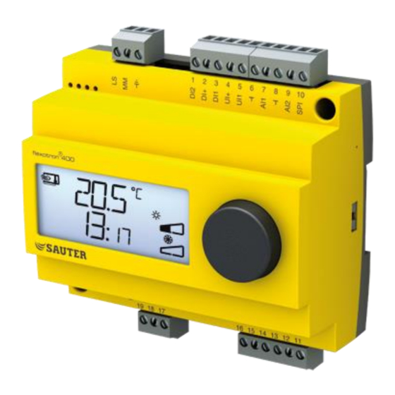
SAUTER flexotron®400 - RDT405 Introduction to flexotron®400 Introduction to flexotron®400 flexotron®400 controllers The controllers flexotron®400 is a range of pre-programmed, configurable controllers that can be set to handle everything from temperature to CO control or pressure control. Features also include a general control usable for several different control modes, such as humidity control or other applications. - Page 6 SAUTER flexotron®400 - RDT405 Introduction to flexotron®400 In- and Outputs The RDT405 has: 1 analogue input, Ni1000 1 analogue input for an external setpoint device, Ni1000 1 universal input, 0…10 V DC or digital 1 digital input ...
-
Page 7: Technical Data
SAUTER flexotron®400 - RDT405 Technical data Technical data Supply voltage ............... 24 V AC ±15%, 50...60 Hz Power consumption ..................4 VA Ambient temperature ................... 0...50°C Ambient humidity ................Max 95% RH Storage temperature ................–20...70°C Terminals ..Disconnectable, so-called lift type for cable cross-section 1.5 mm Protection class ................ - Page 8 -sensor ....................EGQ212 Humidity sensor (can be used for general control (3)) ....... HSC120 Pressure sensor ....................DSU The accessories are available from Fr. Sauter. For more detailed information, see product sheets and instructions which are available at http://www.sauter- controls.com/de.
-
Page 9: Installation And Wiring
SAUTER flexotron®400 - RDT405 Installation and wiring Installation and wiring Installation The controller flexotron®400 must be mounted in a DIN-standard casing (minimum 7 modules) or in a cabinet, either on a DIN-rail or, using the two screw- pockets provided, by being screwed to any suitable flat surface in the cabinet. - Page 10 SAUTER flexotron®400 - RDT405 Installation and wiring Analogue input AI The analogue inputs must refer to an ground terminal. AI1 is for Ni1000 temperature sensors only. Temperature range: -20…+140°C. SPI is only intended for a Ni1000 setpoint device, the range is 0...40°C.
-
Page 11: Control Modes
SAUTER flexotron®400 - RDT405 Control modes Control modes flexotron®400 can be configured to any one of the following control modes. 1. Temperature control. The temperature at the sensor is kept at the setpoint value by controlling the output signals on AO1 and AO2. A single PI control loop is used. -
Page 12: Control Mode 1, Temperature Control
SAUTER flexotron®400 - RDT405 Control modes Control mode 1, Temperature control The analogue outputs can be configured to the following combinations: 1. Heating 2. Cooling 3. Heating Cooling 4. Heating Heating 5. Cooling Cooling 6. Heating Damper 7. Cooling Damper 8. - Page 13 SAUTER flexotron®400 - RDT405 Control modes monitoring the supply water temperature to open/close the input. Open contact will give heating control and closed contact cooling control. Damper In applications with dampers it is often desirable to be able to set a minimum amount of fresh air.
-
Page 14: Control Mode 2, Co Control
SAUTER flexotron®400 - RDT405 Control modes Control mode 2, CO control The output signal will increase when the CO -value rises above the setpoint value. The CO -sensor must have a 0...10 V DC output for example: Room sensors Duct sensor The transmitter range cannot exceed 9900 ppm at 10 V DC output. -
Page 15: Control Mode 3, General Control 0
SAUTER flexotron®400 - RDT405 Control modes Control mode 3, General control 0…100% Humidity control has been selected as an example: The control mode consists of a general control in sequence. A neutral zone can be set between AO1 and AO2. -
Page 16: Control Mode 4, Pressure Control
SAUTER flexotron®400 - RDT405 Control modes Control mode 4, Pressure control The output signal will increase when the pressure signal falls below the setpoint value. The pressure transmitter must have an output signal of 0...10 V DC, for example: DSU. -
Page 17: Control Mode 5, Pressure Control With Outdoor Temperature Compensation Of The Pressure Setpoint
SAUTER flexotron®400 - RDT405 Control modes Control mode 5, Pressure control with outdoor temperature compensation of the pressure setpoint. The output signal will increase when the pressure signal falls below the setpoint value. The AO1 inverted signal is received from AO2. -
Page 18: Display And Encoder
SAUTER flexotron®400 - RDT405 Display and encoder Display and encoder All setting and configuration is done using the display and encoder. The menu information on the display is organised in a tree fashion. Using the encoder you can move between menus, set values etc. - Page 19 SAUTER flexotron®400 - RDT405 Display and encoder Calculated setpoint In control mode 4, Pressure control with outdoor compensation, the controller does not work towards a fixed setpoint value. Instead, it works towards a calculated setpoint, which varies with the outdoor temperature. The calculated setpoint is displayed by turning the knob clockwise when in the Base Display.
-
Page 20: Setpoint
SAUTER flexotron®400 - RDT405 Setpoint Setpoint The setpoint menu is normally accessed from the Base Display by a clicking on the encoder knob. If you wish to change the displayed value, click on the knob again and the change indicator ( ) will start to flash to show that you are now in change mode. -
Page 21: Configuration
SAUTER flexotron®400 - RDT405 Configuration Configuration All the configuration menus lie in the 10-seconds level. This level is accessed from the Base Display by pressing and holding the encoder button for 10 seconds. The display must light up before the button is depressed. It lights up when the button is touched. - Page 22 SAUTER flexotron®400 - RDT405 Configuration will first close to the set minimum value before the heating output on AO1 starts to increase. In alternative 7, Cooling-Damper, at temperatures below the setpoint the damper on AO2 will be fully open. On increasing cooling demand, the damper on AO2 will first close to the set minimum value before the cooling output on AO1 starts to increase.
- Page 23 SAUTER flexotron®400 - RDT405 Configuration 8.1.3 Menus X.3 P-band Here you set the P-band (Proportional band) The P-band unit depends on the choice of control mode. The P-band is the control offset necessary to drive an output signal from 0 to 100%. In configurations involving two outputs the same P- band applies to both outputs.
- Page 24 SAUTER flexotron®400 - RDT405 Configuration 8.1.7 Menu 1.6 Choice of temperature ranges for AI1 (Control mode 1) For control mode 1, it is possible to choose between three different temperature ranges: Range 1: -20…+60°C Range 2: 20…100°C Range 3: 60…140°C 8.1.8...
- Page 25 SAUTER flexotron®400 - RDT405 Configuration 8.1.10 Menu 1.E External setpoint (control mode 1) In this menu, you set whether you want to use an external setpoint device or set the setpoint via the display. External setpoint can be used for control mode 1.
-
Page 26: Index
SAUTER flexotron®400 - RDT405 Index Index Analogue outputs ......... 10 Digital inputs ..........10 Universal inputs ........... 10 Installation ............9 10 second level ..........19 I-time..............23 Analogue inputs ..........10 LVD..............7 Analogue outputs ..........10 Menu Basic level............18 Configuration .......... - Page 27 SAUTER flexotron®400 - RDT405 Index Printed in Switzerland © Fr. Sauter AG Im Surinam 55 CH-4016 Basel Tel. +41 61 - 695 55 55 Fax +41 61 - 695 55 10 www.sauter-controls.com info@sauter-controls.com P100012100...
Need help?
Do you have a question about the flexotron 400 Series and is the answer not in the manual?
Questions and answers