Advertisement
Quick Links
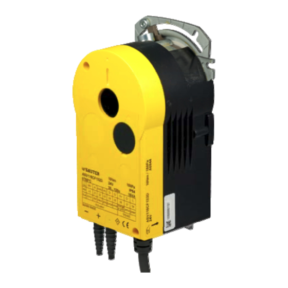
VAV compact controllers
PDS 52.100
ASV115: VAV compact controller, standard version
How energy efficiency is improved
Provides demand-led control of the air volume to optimise energy consumption in ventilation systems. Differen-
tial pressures of up to 1 Pa can be controlled, providing very small air volumes with extremely low duct pressures
and energy consumption.
Areas of application
Controlling supply and exhaust air in, for example, offices, conference rooms or hotel rooms in conjunction with
an air volume box or a damper and a flow probe.
Features
Static measurement of differential pressure based on the capacitive method
Can be used in areas with dirty or contaminated exhaust air
High-precision measurement of differential pressures with ranges of up to 300 Pa
Variable running times from 30 to 120 seconds
Brushless DC motor provides the lowest possible energy consumption and a long service life
Electronic torque cut-off for safe operation
Easy to fit due to self-centring spindle adaptor
Transmission can be disengaged for manual adjustment and positioning of the damper
Power cable 0.5 m long, 10 0.32 mm², fixed to housing
Can easily be combined with RLE150F100 or NRT300
Fail-safe control for critical applications
RS-485 bus interface for up to 31 subscribers in a segment with SLC (SAUTER Local
Communication) protocol
Easy to parameterise using the SAUTER CASE VAV software
Constant air volume control using parameterisable inputs
Technical description
Power supply 24 V~/=
Variable end values for the differential pressure's measuring range:
50...150 Pa
100...300 Pa
Efficient control algorithm
Output signal 0...10 V for:
Air volume, actual value r
Air volume, control deviation –e
or for damper position r
Input signal 0...10 V for:
Command variable c
q
Setpoint shift c
(
)
q ad
Priority control via switch contacts
Zero point with calibration facility
Products
Type
Version with standard cable
ASV115CF132D
ASV115CF132E
Version with halogen-free cable
ASV115CF132I
ASV115CF132K
Technical data
Electrical supply
Power supply
Power consumption
at nominal voltage 50/60 Hz
after a running time of
in operation at 10 Nm (AC/DC)
3)
when idle
(AC/DC)
Integrated damper size
Running time for 90° angle of rotation
Angle of rotation
www.sauter-controls.com
en Product Data Sheet
q
q
Measuring range p (gain=1)
1)
Torque
at 24 V~
(Nm)
10
10
10
10
24 V~ ± 20%, 50...60 Hz
2)
24 V=
± 20%
30 s
120 s
5.7 VA/3.3 W
4.8 VA/3 W
4.2 VA/2.1 W
4.2 VA/2.1 W
4)
30...120 s
5)
90°
(Pa)
0...150
0...300
0...150
0...300
Integrated damper size (continued)
Permissible size of damper shaft
Permissible hardness of damper shaft max. 300 HV
Resistance to transient voltages
Noise during operation
p sensor
Range p (gain = 1)
Pressure range Type D & I/E & K
Non-linearity
Time constant
Power supply
24V~/=
24V~/=
24V~/=
24V~/=
Ø 8...16 mm
6.5...12.7 mm
500 V (EN 60730)
< 30 dB(A)
0...150/300 Pa
2% FS
0.05 s
ASV115
Weight
(kg)
0.8
0.8
0.8
0.8
1/13
Advertisement

Related Manuals for sauter ASV115


Summary of Contents for sauter ASV115
- Page 1 Can easily be combined with RLE150F100 or NRT300 Fail-safe control for critical applications RS-485 bus interface for up to 31 subscribers in a segment with SLC (SAUTER Local Communication) protocol Easy to parameterise using the SAUTER CASE VAV software ...
- Page 2 6) Brief overload; the sensor's zero-point adjustment is recommended 7) Recommend hardness of tubes < 40 Sha (e.g. silicone) 8) Connection 02 can be configured as an analogue input or analogue output using SAUTER CASE VAV software 9) Digital inputs for external potential-free contacts (gold-plated recommended)
- Page 3 ASV115 Connection plan For configuration purposes, the specifications for the air volume box must be loaded into the drive using SAUTER CASE VAV. The data Connection Colour coding Function below are required for this purpose as a minimum. External command variable 0…10 V ...
- Page 4 > 11.4 V Damper open *) Switching hysteresis is 0.4 V (4%) as the default value The function can be set using Sauter CASE VAV 1.4 or higher, Seepage suppression which allows one of the following applications for the device to be...
- Page 5 The parameters for these are set freely configured and a start value of 2 V (P1 ) corresponding to - using the SAUTER CASE VAV software. The use of normally open 40% (P1 ) was chosen with an end value of 10 V (P2 ) correspond- contacts for priority control is parameterised ex factory.
- Page 6 The SAUTER CASE VAV software enables zeroing and setting of setting). The initialisation procedure in the event of a power failure damping factors by the user as required. can be disabled by setting a parameter in the SAUTER CASE VAV software tool. Sensor structure...
- Page 7 100 results in a 10 mV voltage drop with an The housing must not be opened. ASV115 connected. If ten ASV115s are connected to this cable in series, the resultant voltage drop is 100 mV or an error of 1%.
- Page 8 ASV115 The length of the bus cable is limited by the following parameters: Additional technical information Number of devices connected The upper section of the housing with the lid and the lid-release Cross-section of cable button contains the electronics and the sensor. The lower section of...
- Page 9 ASV115 Block diagram controller first priority reference variable generator -eqV.s first priority second priority command reference variable switch generator logic second priority command cqV.p.ad -eqV.s switch controller EIA-485 Wiring diagram Blau Braun Schwarz Grau Violett Weiss Orange Rosa Gelb Grün...
- Page 10 ASV115 Plant schematic (example 1) p EY-modulo p EY-modulo VAV compact controller, ASV115 Room temperature controller, NRT300 Reducing box Building Management System (BMS), night mode Air volume parameters ( supply exhaust 4 V Air volume, setpoint = 40% qV.s...
- Page 11 ASV115 Air volume parameters (Room positive pressure supply exhaust 4 V Air volume, setpoint = 40% qV.s Master (supply air) = 20% = 100% = 1000 m³/h Master (exhaust air) = 20% = 100% = 900 m³/h c-factor 100 (...
- Page 12 ASV115 Plant schematic (example 2) p EY-modulo p EY-modulo VAV compact controller, ASV115 Room temperature controller, NRT300 Reducing box Building Management System (BMS), night mode Air volume parameters ( supply exhaust 4 V Air volume, setpoint = 40% qV.s...
- Page 13 Air volume, actual value, master = 40% 4 V 440 m³/h Air volume, actual value, master = 40% © Fr. Sauter AG Im Surinam 55 CH-4016 Basle Tel. +41 61 - 695 55 55 Fax +41 61 - 695 55 10 www.sauter-controls.com...
Need help?
Do you have a question about the ASV115 and is the answer not in the manual?
Questions and answers