Table of Contents
Advertisement
Quick Links
This document describes the TN100 RF evaluation kit (TN100/M32B-EVAL) used to
evaluate the capabilities of the TN100 device for ranging operations and RF data
transmission based on the Chirp technology.
The entire package consists of two TN100 sensor boards (version 1.1) and a complete
software package.
Both boards are exactly the same and are equipped with:
■
a board (TN100-RCM) which integrates both an STM32 microcontroller and a TN100
transceiver
■
a set of sensors to detect temperature and accelerations
■
one reset (S1) and three general-purpose buttons (S2 to S4)
■
four general-purpose LEDs (LD1 to LD4), Tx/Rx activity LED (LD5), power supply LED
(LD6)
The sensor boards act as source of information providing data regarding distance
measurement (ranging), temperature, accelerations, and status.
The software consists of:
■
The ST TN100 Application running on a host PC used to interact with the sensor boards
and easily perform ranging operations, packet data transmission, and retrieval of on-
board sensor data. Additionally, it offers a graphical representation of the two-node
network constituted by the sensor boards.
■
Firmware running on the STM32 microcontroller including: driver for the TN100 device,
drivers for all the sensors such as MEMS, temperature, internal protocol used to
exchange data, and commands, among nodes and the PC.
More details on boards and software are provided in the following sections.
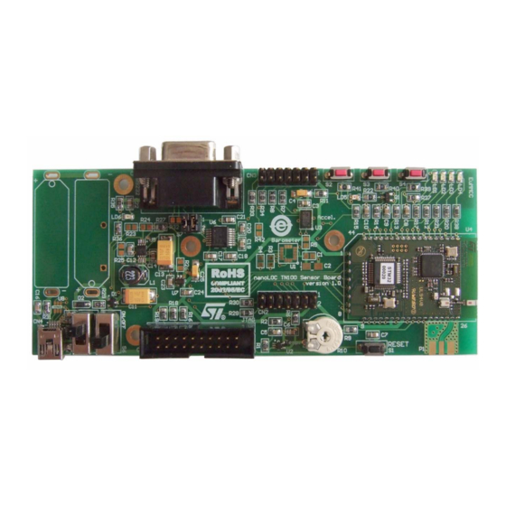
Figure 1.
January 2009
TN100 sensor board with STM32 microcontroller
TN100 RF evaluation kit
Rev 1
UM0579
User manual
www.st.com
1/37
Advertisement
Table of Contents

Subscribe to Our Youtube Channel
Related Manuals for ST TN100 RF


Summary of Contents for ST TN100 RF
- Page 1 The software consists of: ■ The ST TN100 Application running on a host PC used to interact with the sensor boards and easily perform ranging operations, packet data transmission, and retrieval of on- board sensor data. Additionally, it offers a graphical representation of the two-node network constituted by the sensor boards.
-
Page 2: Table Of Contents
Contents UM0579 Contents Reference information ........4 Acronyms and definitions . - Page 3 UM0579 Contents Upload firmware using HyperTerminal ......24 Upload firmware using TN100 application ......25 Loading the boot loader into the sensor board .
-
Page 4: Reference Information
References TN100 RF board datasheet TN100 High performance CSS transceiver enabling location awareness datasheet LIS302DL MEMS motion sensor 3-axis STLM20W87F analog temperature sensor STM32F103CB STM32 ARM-based 32-bit MCU Please check the STMicroelectronics web site www.st.com for any available updates. 4/37... -
Page 5: Description Of The Delivered Package
ST's STM32 family of 32-bit Flash microcontrollers is based on the breakthrough ARM Cortex™-M3 core - a core specifically developed for embedded applications. The STM32 family benefits from the Cortex-M3 architectural enhancements including the Thumb®-2 instruction set to deliver improved performance with better code density, significantly faster response to interrupts, all combined with industry leading power consumption. -
Page 6: Software Overview
Figure 2. TN100 RF board The smart TN100 RF board is only 39 mm by 24 mm and less than 3 mm thick. Yet, it integrates all required components for a complete RF circuit based on the innovative transceiver. As well as the chip, this board includes the ST STM32 microcontroller (MCU), a band pass filter, a balun and an integrated 2.4 GHz chip antenna. - Page 7 UM0579 Description of the delivered package Figure 3. TN100 application window Basically, the application running on the PC cooperates with the firmware running on the sensor nodes and it is able to: ● Get specific parameters such as MAC address, channel, FEC, MAC retries, and so on, for each sensor node ●...
-
Page 8: Tn100 Sensor Board
TN100 sensor board UM0579 TN100 sensor board The TN100 sensor board includes the TN100 high performance chirp spread spectrum transceiver enabling location awareness using an STM32F103 Cortex™-M3 32-bit microcontroller. It provides the following features: ● Sensors – Temperature meter (U2)- STLM20 (analog) –... -
Page 9: Description Of Connectors
UM0579 TN100 sensor board Description of connectors 3.1.1 JTAG connector (CN1) The 20-pin connector (CN1) provides the JTAG interface as shown in Figure 5. This interface is primarily used for communicating with a PC using a suitable converter box such as J-Link from IAR Systems™. -
Page 10: Extension Connector (Cn3)
TN100 sensor board UM0579 Table 3. Extension connector (CN2) pin description STM32 pin STM32 pin STM32 pin 2.5 V DC PC13 3.1.3 Extension connector (CN3) The 14-pin extension connector CN3 can be used together with the CN2 connector to connect an extension. The CN2 to CN3 pitch distance is 2.54 mm so it makes it possible to connect a standardized bread board or other extension. -
Page 11: Rs-232 Connector (Cn5)
UM0579 TN100 sensor board Table 5. USB connector (CN4) pin description Connector pin +5 V D– (not used with nanoLOC TN100 board) D+ (not used with nanoLOC TN100 board) 3.1.5 RS-232 connector (CN5) The RS-232 communication is realized by the RS-232 transceiver connected to the USART1 microcontroller serial channel. -
Page 12: General-Purpose And Reset Buttons
TN100 sensor board UM0579 Table 7. RS-232 lines TX and RX, cross or direct cable selection RS-232 cable selection Jumper selection Crossed AM00267 Direct AM00268 General-purpose and reset buttons There are four push-buttons available on the board. S1 is a system reset button. Buttons S2 to S4 can be used as general-purpose. -
Page 13: Led Indicators
UM0579 TN100 sensor board Table 8. General-purpose and reset buttons description table (continued) Board pin Microcontroller Reference Function Schematics connection pin connection 0 Ω 100 Ω General-purpose 100 nF GM: DT2112C AM00275 PA 8 0 Ω 100 Ω General-purpose 100 nF GM: DT2112C AM00276 LED indicators... -
Page 14: Power Supply
430 Ω PB10 General-purpose PB10 470 Ω AM00277 4.7 kΩ 1.8 kΩ TX/RX activity 2.5 V 100 Ω ST: MMBTA92 AM00278 5V0_JTAG GM: P- B143 1 S5 V BUS GM: USB-MINI B F SMD D– External source voltage supply SHLD... - Page 15 UM0579 TN100 sensor board Figure 11. USB connector (CN4) AM00265 Table 10. CN4 pins description Signal + 5 V V Figure 12. JTAG connector - CN1 8 10 12 14 16 18 20 11 13 15 17 19 AM00262 Table 11. CN1 pins description Signal + 5 V...
-
Page 16: Getting Started
Following are described the steps to setup the kit and to start working with it. Double-click on the tn100demo.exe file to install the software application. In the ST TN100 Demo Setup: Installation Folder dialog box, select the destination folder and click Install. -
Page 17: Application Description
UM0579 Getting started Application description 4.2.1 Running the application Connect one of the two sensor boards - using the RS232 connector - to the host PC by means of the provided serial cable. The connected board will became the Gateway and will manage the messages coming from the PC and the other sensor nodes. -
Page 18: Sensing And Control
Getting started UM0579 The Toolbar contains the following buttons: ● Refresh, to let the Application detect any update on the nodes network ● Scroll to end, to automatically scroll to the newly inserted row in the Packet Log view ● COM port, to display information about the COM port currently in use Figure 15. -
Page 19: Ranging
UM0579 Getting started Figure 16. Sensor board parameters Furthermore, this view can be used to upload the firmware on the Gateway and to restart the firmware in any node. For further information on how to upload a new firmware, please Section 5.2: Upload firmware using TN100 application. - Page 20 Getting started UM0579 Insert how many samples (measures) must be taken into account by the sensor board to calculate an interim average (for example, AS). Default value is 1. Note: The data in the two fields are linked in the following way: the sensor board sends one average value calculated on AS samples and the process lasts NT times.
-
Page 21: Data Tx/Rx
UM0579 Getting started 4.2.5 Data Tx/Rx Click the “+” expander on the left of the Data Tx/Rx item to expand the Data transmission/reception view. Figure 20. Data Tx/Rx view expander Select the two nodes participating to the data transmission/reception session within the Tx and Rx drop-down lists respectively. -
Page 22: Send Messages
Getting started UM0579 4.2.6 Send messages In addition to exchanging data between the two sensor boards, it is also possible to have them exchange text messages. Click the “+” expander on the left of the Send Messages item to expand the view. Figure 22. -
Page 23: Packet Log
UM0579 Getting started 4.2.8 Packet log The aim of the Packet Log view is to display detailed information which can be used for debugging reasons; this view is not intended to be used under normal application operation. The table format of such information is organized according to the following fields: ●... -
Page 24: Updating Firmware Nodes
Updating firmware nodes UM0579 Updating firmware nodes The sensor board firmware may be updated through the serial connection using both the TN100 Application or directly through a HyperTerminal using the preloaded boot loader code. If for some reason the boot loader is corrupted, please refer to Section 5.3: Loading the boot loader into the sensor board. -
Page 25: Upload Firmware Using Tn100 Application
UM0579 Updating firmware nodes Keep the S2 button pressed and then press and release the RESET button; LEDs LD2, LD3, and LD4 will blink continuously and the HyperTerminal appears as shown in Figure Press “1” key as indicated by the HyperTerminal to download the firmware. In the Transfer menu, select Send File …... -
Page 26: Loading The Boot Loader Into The Sensor Board
Updating firmware nodes UM0579 Loading the boot loader into the sensor board In order to check whether the boot loader is present or not, please do the following: Keep button S2 pressed and reset the board via button S1. LEDs LD2, LD3 and LD4 should now blink as confirmation that the boot loader is present and running. -
Page 27: Appendix A Board Assembly Setup Manual
UM0579 Board assembly setup manual Appendix A Board assembly setup manual Table 14. Board assembly setup manual Resistor Value (Ω) Assembled Not assembled General-purpose buttons PA8 MCU pin is disconnected from PA8 MCU signal is connected to the the button S4 and can be freely used general-purpose button S4. - Page 28 Board assembly setup manual UM0579 Table 14. Board assembly setup manual (continued) Resistor Value (Ω) Assembled Not assembled Connects MEMS interrupt 2 pin of the PB14 MCU pin is disconnected from accelerometer to the PB14 MCU pin the MEMS interrupt 2 pin of the which can be configured as an accelerometer and can be freely external interrupt line.
-
Page 29: Appendix B Bill Of Materials
Farnell: 1125348 MINI-B, SMT, W/PEGS GM: CAN 9 Z 90 RS-232 DB9 female Farnell: 1186091 connector SPC Technology: SPC15457 Diode SOT-23 ST: BAT54CFILM Diode SOD-123 ST: STPS0520Z Coilcraft: DO1813H-223ML 22 µH, SMT power inductor Coilcraft: DO1608C-153ML LD1, LD2, LD3, LD4 Yellow... - Page 30 Farnell: 1197660 Tyco: SLS121PCFN GM: S2G4 Header 2X2 Farnell: 1278358 Molex: 10-89-7082 Barometer LGA16 ST: LPS004DL Temperature meter SOT323-5 ST: STLM20W87F MEMS accelerometer LGA14 ST: LIS302DL NanoLOC_STM32_Module _P182 DC step up converter MSOP8 ST: L6920DC RS-232 transceiver TSSOP20 MAXIM: MAX3319ECAE Ultra low drop-low noise SOT23.5...
-
Page 31: Appendix C Artwork Prints
UM0579 Artwork prints Appendix C Artwork prints This section shows the layout of the evaluation board PCB (top and bottom layers). Figure 28. Evaluation board PCB (top layer) 31/37... - Page 32 Artwork prints UM0579 Figure 29. Evaluation board PCB (bottom layer) 32/37...
-
Page 33: Appendix D Schematic Diagrams
UM0579 Schematic diagrams Appendix D Schematic diagrams Figure 30. LED and button schematics 33/37... - Page 34 Schematic diagrams UM0579 Figure 31. Power supply schematics 34/37...
- Page 35 UM0579 Schematic diagrams Figure 32. Sensor and RS-232 communication schematics 35/37...
-
Page 36: Revision History
Revision history UM0579 Revision history Table 16. Document revision history Date Revision Changes 21-Jan-2009 Initial release. 36/37... - Page 37 No license, express or implied, by estoppel or otherwise, to any intellectual property rights is granted under this document. If any part of this document refers to any third party products or services it shall not be deemed a license grant by ST for the use of such third party products or services, or any intellectual property contained therein or considered as a warranty covering the use in any manner whatsoever of such third party products or services or any intellectual property contained therein.
Need help?
Do you have a question about the TN100 RF and is the answer not in the manual?
Questions and answers