
Subscribe to Our Youtube Channel
Related Manuals for Parker LX80L


Summary of Contents for Parker LX80L
- Page 1 Manual No. 101-1182-01 Rev. 2 LX80L Precision Grade Parker Product Manual Effective: September 15, 2004 Supersedes: - Electromechanical Positioning Systems Automation...
-
Page 2: Important User Information
The products described herein, including without limitation, product features, specifications, designs, availability and pric- ing, are subject to change by Parker Hannifin Corporation and its subsidiaries at any time without notice. The information in the product manual, including any apparatus, methods, techniques, and concepts... -
Page 3: Table Of Contents
LX80L Series Product Manual LX80L Series Product Manual Table of Contents IMPORTANT USER INFORMATION..........................2 REVISION NOTES................................4 CHAPTER 1 - INTRODUCTION ............................5 ..............................6 RODUCT ESCRIPTION ..................................6 NPACKING ..............................7 ETURN NFORMATION ..............................7 EPAIR NFORMATION ............................7 ARNINGS AND RECAUTIONS ............................8 PECIFICATION ONDITIONS ..............................9... -
Page 4: Revision Notes
LX80L Series Product Manual Revision Notes Revision 1 Original Document Revision 2 Clarified motor lead connection on page 48 Reduced “Rated Load” on page 15 from 5, 10, 5, 10 to 3, 3, 6, 6 respectively Added “Maximum Moment Load” to Specification Table on page 15, and note... -
Page 5: Chapter 1 - Introduction
LX80L Series Product Manual C H A P T E R O N E Introduction IN THIS CHAPTER • Product Description................6 • Unpacking ..................6 • Return Information................7 • Warnings and Precautions..............7 • Specification Conditions ..............8 •... -
Page 6: Product Description
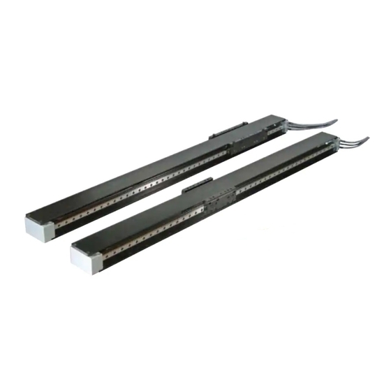
LX80L Positioner Although the LX80L is small in size and weight, it is large on performance and reliability. All key com- ponents are integral to the unit - residing within the body of the stage to provide a clean looking, reli- able, unobstructed package. -
Page 7: Return Information
Warnings and Precautions Hot Surfaces DO NOT touch linear motor coils located in the carriage of the LX80L after high duty operation. Mo- tor temperature may approach 60°C. The unit itself may become warm or hot to the touch. Electrical Shock DO NOT take apart or touch any internal components of the positioner while unit is plugged into an electrical outlet. -
Page 8: Specification Conditions
LX80L Series Product Manual Specification Conditions Specifications Are Temperature Dependent Catalog specifications are obtained and measured at 20 Degrees C. Specifications at any other temperature may deviate from catalog specifications. Minimum to maximum continuous operating temperature range (with NO guarantee of any specification except motion) of a standard unit before failure is 5 - 40 degrees C. -
Page 9: Assembly Diagram
LX80L Series Product Manual Assembly Diagram Extension Cables Exit Either Side Travel Linear Motor, Encoder, & Home/Limits Embedded in Carriage Endblock Cable Side Carriage Cover Base Endblock Square rail Non-cable bearing Parker Hannifin Corporation EMN Automation - Parker Irwin, Pennsylvania... -
Page 10: Lx80L Product Highlights
LX80L Series Product Manual LX80L Product Highlights Parker Hannifin Corporation EMN Automation - Parker Irwin, Pennsylvania... -
Page 11: Chapter 2 - Table Specifications
C H A P T E R T W O Table Specifications IN THIS CHAPTER • Order Number Nomenclature .............12 • Dimensional Drawings - LX80L ............13 • Dimensional Drawings - MX80L Compatibility ........14 • General Table Specifications..............15 • Test Methodology................16 •... -
Page 12: Order Number Nomenclature
LX80L Series Product Manual Order Number Nomenclature Parker Hannifin Corporation EMN Automation - Parker Irwin, Pennsylvania... -
Page 13: Dimensional Drawings - Lx80L
LX80L Series Product Manual Dimensional Drawings - LX80L Parker Hannifin Corporation EMN Automation - Parker Irwin, Pennsylvania... -
Page 14: Dimensional Drawings - Mx80L Compatability & Z-Brackets
LX80L Series Product Manual Dimensional Drawings - MX80L Compatibility The direct mount compatibility of the LX80L and compatibility with the MX80 family enables a large variety of two and three axis systems. Possible configurations include XY systems where LX80s serve as the base axis and either an LX80 or MX80 serve as the Y axis. -
Page 15: General Table Specifications
*For any direction, for moment loads larger than stated, the use of an Idler Rail Assembly is recommended, see page 29 LX80L Mass in kg (Does not include external extension cables) 8 POLE MOTOR 8 POLE MOTOR 16 POLE MOTOR... -
Page 16: Test Methodology
6.32 -3.68 Published accuracy and repeatability specifications are subject to the testing methodology. Parker’s methodology provides specifications over the entire table travel regardless of start or finish position. The accuracy and repeatability specifications are based on the peak to peak error measured by a la- ser interferometer and prism located at 38mm above the center of the table. -
Page 17: Lx80L Series Technical Data
Linear Bearing Life-Load All Travels The precision linear bearings used in the LX80L are sized to provide virtually unlimited life, 100,000,000 inches of travel guaranteed. The bearings provide stable and accurate linear motion while maintaining high rigidity even under combined of fluctuating loads. The double rail design offers the best load capacity, straightness, flatness, and stability. - Page 18 LX80L Series Product Manual Moment Deflection – Load Charts for Double Rail Tables LX80L MOMENT DEFLECTION 8 Pole Motor - Double Rail 30.000 PITCH ROLL 25.000 20.000 15.000 10.000 5.000 0.000 M OM EN T ( N - M )
- Page 19 LX80L Series Product Manual Moment Deflection – Load Charts for Single Rail Tables LX80L MOMENT DEFLECTION 8 Pole Motor - Single Rail PITCH 700.0 ROLL 600.0 500.0 400.0 300.0 200.0 100.0 MOMENT (N-M) LX80L MOMENT DEFLECTION 16 Pole Motor, Single Rail PITCH 800.000...
-
Page 20: Force/Speed Charts
LX80L Series Product Manual Force/Speed Charts The Force/Speed Charts for the LX80L are shown for each motor size, 8 pole and 16 pole. The mo- tor force is the same for 80 and 48 VDC bus voltage. See Electrical Specifications for motor pa- rameters. -
Page 21: Electrical Specifications
LX80L Series Product Manual Electrical Specifications Specifications for both the 8 pole (D13) and 16 pole (D17) linear servo motors Parameter: Symbol: Units: 8 Pole 16 Pole 7.20 13.00 Stall Force Continuous [1] 1.85 1.66 Stall Current Continuous [1, 4, 8]... -
Page 22: Cleanroom Preparation
* Compatibility is defined as not affecting the cleanroom class rating with the addition of this product for classes shown. The Class 1 rating in the table refers to class 1 levels of 0.3µ and larger particles detected in Parker’s Class 10 chamber. -
Page 23: Encoder Specifications
LX80L Series Product Manual Encoder Specifications Description Specification Input Power 5 VDC +/-5% 150 to 220 mA depending on encoder resolution Output Square wave differential line driver (EIA RS422) 2 channels A and B in (Incremental) quadrature (90 ) phase shift. -
Page 24: Cable And Wiring Diagrams
LX80L Series Product Manual Cabling and Wiring Diagrams Connector Pin Out and Extension Cable Wire Color Codes for the 5, 1, 0.5 and 0.1 micron resolution encoders Feedback-Hall Connector Limits Connector Motor Leads LIMITS CONNECTOR FEEDBACK-HALL CONNECTOR FUNCTION WIRE COLOR... -
Page 25: Chapter 3 - Setup And Usage
LX80L Series Product Manual C H A P T E R T H R E E Setup and Usage IN THIS CHAPTER • Mounting Orientations................26 • Mounting Surface ................27 • Load Mounting ...................28 • Idler Rail Assembly ................29 • Setting Limit/Home sensors ...............31 •... -
Page 26: Mounting Orientations
LX80L Series Product Manual Mounting Orientations The LX80L can be mounted horizontal, inverted, or side. For all mounting orientations, the ca- bles should be secured as to not interfere with the movement of the carriage and bearings. For inverted, side, and vertical mounting, the main table cover must be used. -
Page 27: Mounting Surface Requirements
LX80L Series Product Manual Mounting Surface Requirements Proper mounting of the LX80L is essential to optimize product performance. All specifications are based on the following conditions: • The positioner must be bolted down using all mounting holes provided in the base. There are two different mounting surfaces for the LX80L, as seen below. -
Page 28: Load Mounting Requrements
Load Mounting Requirements Dowel holes are included in the top of the carriage of the LX80L for repeatable mounting of loads/fixturing. Use appropriate length bolt. The LX80L compact design requires proper sized bolts to be used when mounting payloads to the car- riage. -
Page 29: Idler Rail Assembly
LX80L Series Product Manual Idler Rail Assembly When using the LX80L in a gantry or “H” configu- ration, as shown, it is recommended that Y-Axis Parker’s Idler Rail Assembly is used. The Idler Rail Assembly has the same surface mounting requirements as the LX80L, see page #21 “Mounting Surface Requirements”. - Page 30 • Align the centerline of the Idler Rail Assembly with the centerline of the X- Axis LX80L, see page #10 for LX80L centerline dimension. • Offset the Idler Rail Assembly’s “Travel Centerline” from the X-Axis Travel Centerline.
-
Page 31: Limit And Home Sensor Operation
Option Upgrades Limits and Homes can not be added to the LX80L table in the field due to the integrated design which encloses the sensor on a printed circuit board in the carriage. If the optical sensor limit and home are desired the unit must be returned to the factory on an RMA. -
Page 32: Adjusting The Limit Triggers
LX80L Series Product Manual See the following example for calculating maximum deceleration for an application with a payload = 0.25 kg on an LX80-T02, 8 - Pole motor, double rail table with a maximum speed of 500 mm/s. Total mass = 0.633 kg (Payload mass = 250 grams + Carriage mass (383 grams) = 633... - Page 33 LX80L Series Product Manual Step 4: Gently remove the existing Limit trigger decal with a razor blade or with your finger nail. Dispose of this decal, Do Not Reuse Decals, adhesive may not adhere properly if reused resulting in decal falling off and stage crashing into end stops.
-
Page 34: Setting Home Sensor
The Z-channel is a unidirectional device. This means that the final homing direction must occur in one direction. The LX80L is set that the final home direction is to be toward the positive end of the table. The repeatability of the Z-channel is equal to the repeatability of the table. -
Page 35: Cabling
LX80L Series Product Manual Cabling The LX80L is provided with high flex cabling which is strain relieved at the connection point on the posi- tioner. • The Hall/Encoder cable is terminated with a high density 15 pin D-sub connector which is compatible with the ViX drive from Parker. - Page 36 LX80L Series Product Manual Step 3: Reverse the wires to come out the opposite direction. The cables must be in order from top to bottom based on the connector location on the circuit board, not all of the cables are the same diameter so they are to match the endblock cover/strain relief re- cesses.
-
Page 37: Internal Cable Replacement
Due to the continuous motion of the internal cable system, it may be necessary to replace at some point during the positioner’s life. The internal cable assembly should provide a long service life, Parker has tested the internal cable assembly in excess of 20 million cycles. Follow the instructions and images to replace the internal cable assembly. - Page 38 LX80L Series Product Manual Step 7: Remove the cable assembly from the carriage by removing one (1) flat head screw from the cable carrier link that is attached to the carriage. It is necessary to lift the four (4) connectors to gain access to the flat head screw.
-
Page 39: Y-Axis Cable System
LX80L Series Product Manual Y-Axis Cable System When using two LX80L positions in an X-Y configuration care must be taken with the cable management of the Y-axis extension cables. These cables will need to flex through the entire travel of the X-axis positioner. - Page 40 LX80L Series Product Manual Step 7: Connect the stationary end of the Y-Axis Cable System with two (2) socket head cap screws to the same mounting surface as the x-axis positioner. See drawing and instructions below for place- ment. Step 8: After the stationary end of the Y-Axis Cable System is se- cured to the mounting surface, move the x-axis positioner’s carriage...
-
Page 41: Chapter 4 - Performance
LX80L Series Product Manual C H A P T E R F O U R Performance IN THIS CHAPTER • Acceleration Limits................42 • Speed Limits ..................43 • Thermal Effects on Accuracy and Repeatability........ 29 Parker Hannifin Corporation EMN Automation - Parker... -
Page 42: Acceleration Limits
• Linear Bearings The linear bearings used in the LX80L have a continuous acceleration limit of 2 g’s. This means that the bearings are designed to take repetitive accelerations of 2 g’s and maintain the rated bearing life. Additionally, the bearings can take a periodic acceleration of up to 5 g’s, however continued accelerations of these magnitudes will reduce bearing life. -
Page 43: Speed Limits
Acceleration of linear servo driven tables is typically limited by three (3) factors: • Linear Bearings The linear bearings used in the LX80L are limited to a maximum speed of 3 meters/second. • Linear Encoder Limit The linear encoder has speed limits relative to encoder resolution; these limits are listed below:... -
Page 44: Thermal Effects On Accuraccy
Thermal Effects on Accuracy The LX80L uses a magnet linear servo motor. The magnet rails and the encoder tape are mounted to the base. The motor coils are mounted in the carriage and unless the payload is insulated, the heat generated in the coils should radiate out the payload maintaining a low thermal delta between base and carriage. -
Page 45: Causes For Temperature Increases
LX80L base). Motor heating from LX80L Since the LX80L uses a servo motor as its drive, it produces no heat unless there is motion, or a force being generated. In low duty cycle applications heat generation is low, however as duty cycles increase, temperature of the LX80L will increase, causing thermal expansion of the car- riage. - Page 46 LX80L Series Product Manual Parker Hannifin Corporation EMN Automation - Parker Irwin, Pennsylvania...
-
Page 47: Chapter 5 - Connecting The Vix Amplifier
LX80L Series Product Manual C H A P T E R F I V E Connecting the Vix Amplifier IN THIS CHAPTER • Drive Connections................48 Parker Hannifin Corporation EMN Automation - Parker Irwin, Pennsylvania... - Page 48 Limits use Inputs The ViX drive has 5 digital inputs. When using with LX80L, the EOT Limits and Home use 3 of the 5 inputs. A VM15-PF screw terminal breakout board may be purchased to allow access to the remaining 2 inputs and all of the outputs.
-
Page 49: Chapter 6 - Maintenance And Lubrication
LX80L Series Product Manual C H A P T E R S I X Maintenance and Lubrication IN THIS CHAPTER • Square Rail Bearing Lubrication ............51 Parker Hannifin Corporation EMN Automation - Parker Irwin, Pennsylvania... - Page 50 LX80L Series Product Manual Square Rail Bearing Lubrication Materials Required : Replacement square rail bearing lubrication (See below for lubrication type and ordering information), clean cloth, small brush Lubrication Type For positioners with cleanroom preparation R1, class 1000 compatible (standard): Use NSK#2.
-
Page 51: Appendix A - Internal Protection
LX80L Series Product Manual Appendix A - Internal Protection Parker has conducted testing to determine the degree to which the positioner is protected by using a British standard called an Ingress Protection Rating (IP Rating). The LX80L has an IP 10 protec- tion rating. -
Page 52: Index
LX80L Series Product Manual Index Acceleration Lubrication, 51 Velocity Limits, 42 Maximum, 43 Specifications, 15 Maintenance, 51 Specifications, 15 Accuracy Mass, 15 Specifications, 15 Moment, 18, 19 Amplifier, 48 Thermal Effects, 44 Motor Force, 42 Drive Specifications, 23 Assembly Diagram, 9... - Page 53 LX80L Series Product Manual Notes Parker Hannifin Corporation EMN Automation - Parker Irwin, Pennsylvania...
- Page 54 LX80L Series Product Manual Notes Parker Hannifin Corporation EMN Automation - Parker Irwin, Pennsylvania...
- Page 55 LX80L Series Product Manual Notes Parker Hannifin Corporation EMN Automation - Parker Irwin, Pennsylvania...
Need help?
Do you have a question about the LX80L and is the answer not in the manual?
Questions and answers