Garmin GPSMAP 10X2 Series Owner's Manual
Hide thumbs
Also See for GPSMAP 10X2 Series:
- Owner's manual (112 pages) ,
- Installation instructions manual (10 pages) ,
- Installation instructions manual (8 pages)
Table of Contents
Advertisement
Quick Links
Advertisement
Table of Contents

Related Manuals for Garmin GPSMAP 10X2 Series


Summary of Contents for Garmin GPSMAP 10X2 Series
- Page 1 GPSMAP 10X2/12X2 SERIES ® Owner’s Manual...
- Page 2 © 2019 Garmin Ltd. or its subsidiaries All rights reserved. Under the copyright laws, this manual may not be copied, in whole or in part, without the written consent of Garmin. Garmin reserves the right to change or improve its products and to make changes in the content of this manual without obligation to notify any person or organization of such changes or improvements. Go to www.garmin.com...
-
Page 3: Table Of Contents
Viewing Boat Data on a Garmin Resetting the Station Layouts..10 Watch............ 18 Assigning a Shortcut Key..... 10 Viewing Boat Data on a Garmin Nautix™ Presets..........11 Device............ 18 Saving a New Preset......11 Charts and 3D Chart Views..... 19 Managing Presets...... - Page 4 Mapping a Body of Water Using the Showing Tides and Current Garmin Quickdraw Contours Feature.. 35 Indicators........23 Adding a Label to a Garmin Quickdraw Showing Satellite Imagery on the Contours Map........35 Navigation Chart....... 24 Garmin Quickdraw Community.... 35...
- Page 5 Marking an SOS Location....40 Deleting All Saved Tracks....49 Projecting a Waypoint...... 41 Retracing the Active Track....50 Viewing a List of all Waypoints..41 Clearing the Active Track....50 Editing a Saved Waypoint....41 Managing the Track Log Memory During Recording......
- Page 6 Adjusting the RealVü Sweep Split-Frequency Sonar View..... 59 Speed..........77 Split-Zoom Sonar View..... 59 LiveVü Forward and FrontVü Sonar Garmin ClearVü Sonar View....60 Menu..........78 Garmin SideVü™ Sonar View....61 Setting the LiveVü and FrontVü SideVü Scanning Technology..62 Transducer Transmit Angle..
- Page 7 Setting Up the Timed Transmit Adjusting Rain Clutter on the Radar Mode..........85 Screen..........92 Enabling and Adjusting a Radar No Averaging Multiple Scans on the Transmit Zone........85 Radar Screen......... 92 Adjusting the Radar Range....86 Radar Options Menu......93 Tips for Selecting a Radar Range..
- Page 8 Enabling the Autopilot Controls on a Navigating to a Tracked Vessel..108 Garmin Watch........99 Creating a Waypoint at the Position of Customizing the Autopilot Button a Tracked Vessel......108 Actions..........100 Editing Information in a Position Controlling the Autopilot with a GRID 20 Report..........
- Page 9 Configuring the Heading Source of the Clearing all of the Messages..... 123 Wind Gauge........117 Media Player........ 123 Customizing the Close-Hauled Wind Gauge..........117 Opening the Media Player....123 Viewing Trip Gauges......118 Media Player Icons......123 Resetting Trip Gauges....118 Selecting the Media Device and Battery Management......
- Page 10 On-Screen Controls..... 137 Another Time Period.......131 Configuring the Video Appearance... 138 Weather Fronts and Pressure Centers..........131 Garmin VIRB® Action Cameras..138 City Forecasts......... 132 Connecting a VIRB 360 Action Camera..........138 Viewing Fish Mapping Data....132 Connecting a VIRB Action Camera 138 Viewing Sea Conditions.....
- Page 11 Calibrating a Water-Speed Device. 153 Viewing a Camera Feed Full Screen.. 142 Other Vessels Settings....... 153 Changing the Surround View Camera Settings that are Synced on the Garmin Layout..........142 Marine Network........154 Showing and Hiding the Visual Restoring the Original Chartplotter Bumper..........
- Page 12 My device will not turn on or keeps turning off........162 My device is not creating waypoints in the correct location......162 Contacting Garmin Support....162 Specifications........163 GPSMAP 10x2 Specifications..163 GPSMAP 12x2 Specifications..164 Sonar Models Specifications..164 NMEA 2000 PGN Information..
-
Page 13: Introduction
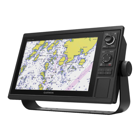
The support ® pages will provide answers to frequently asked support questions, and you can download software and chart updates. There is also contact information to Garmin support should you have any questions. Device Overview Power key... -
Page 14: Keys
Keys Hold to turn on and off the device. Press repeatedly to scroll through the backlight brightness levels. Turn to zoom in or out of a view. Knob Turn to highlight an option in a menu. Press to select a highlighted option. HOME Press to return to the home screen. -
Page 15: Connector View
The connectors and locations vary based upon the model. Pictured is a GPSMAP 1212xsv model. 12-PIN XDCR* 12-pin transducer POWER Power Ground screw CVBS IN Composite video in ETHERNET Garmin Marine Network NMEA 2000 NMEA 2000 ® network *Not available on all models Introduction... -
Page 16: Tips And Shortcuts
1 Select NAV INFO > Owner's Manual. 2 Select a manual. 3 Select Open. Downloading the Manuals from the Web You can get the latest owner's manual and translations of manuals from the Garmin website. 1 Go to garmin.com/manuals/gpsmap10x2-12x2. 2 Download the manual. Garmin Support Center Go to support.garmin.com... -
Page 17: Inserting Memory Cards
Home screen. If the device loses satellite signals, disappears and a flashing question mark appears over on the chart. For more information about GPS, go to garmin.com/aboutGPS. For help acquiring satellite signals, see device will not acquire GPS signals, page 162. -
Page 18: Customizing The Chartplotter
(Warning Manager, page 122). When multiple displays are installed on the Garmin Marine Network, you can group them together into a station. A station enables the displays to work together, instead of as several separate displays. You can customize the layout of the screens on each display, making each screen different on each display. -
Page 19: Adding An Item To Favorites
Adding an Item to Favorites You can add items such as a chart, combo screen, or gauge to the Favorites category. NOTE: If your home screen has been customized by the boat manufacturer, you cannot add an item to the Favorites category. -
Page 20: Customizing The Startup Screen
Customizing the Startup Screen You personalize the image that is displayed when the chartplotter is turning on. For the best fit, the image should be 50 MB or less and conform to the recommended dimensions (Recommended Startup Image Dimensions, page 1 Insert a memory card that contains the image you want to use. -
Page 21: Creating A New Combination Page
Creating a New Combination Page You can create a custom combination page to suit your needs. 1 Select Combos > MENU > Add Combo. 2 Select a window. 3 Select a function for the window. 4 Repeat these steps for each window of the page. 5 Drag the arrows to resize the windows. -
Page 22: Customizing The Data Overlays
Customizing the Data Overlays You can customize the data in the data overlays shown on a screen. 1 Select an option based on the type of screen you are viewing: • From a full screen view, select MENU > Edit Overlays. •... -
Page 23: Presets
Presets A preset is a collection of settings that optimize the screen or view. You can use particular presets to optimize groups of settings for your activity. For example, some settings might be optimal for when you are fishing, and others might be optimal for when you are cruising. -
Page 24: Turning On The Chartplotter Automatically
PIN. NOTICE If you enable the Screen Lock feature, Garmin Support cannot retrieve the PIN or access your device. It is your responsibility to provide the PIN to anyone authorized to use the vessel. 1 Select Settings > System > Sounds and Display > Screen Lock > Setup. -
Page 25: Activecaptain Roles
7 Bring the mobile device within 32 m (105 ft.) of the GPSMAP device. 8 From your mobile device settings, open the Wi‑Fi ® connections page and connect to the Garmin device, using the name and password you entered in the Garmin device. ActiveCaptain App... -
Page 26: Enabling Smart Notifications
Enabling Smart Notifications WARNING Do not read or reply to notifications while operating the vessel. Failure to pay attention to the conditions on the water can result in vessel damage, personal injury, or death. Before your GPSMAP device can receive notifications, you must connect it to your mobile device and to the ActiveCaptain app. -
Page 27: Managing Notifications
Managing Notifications WARNING Do not read or reply to notifications while operating the vessel. Failure to pay attention to the conditions on the water can result in vessel damage, personal injury, or death. Before you can manage the notifications, you must enable the Smart Notifications feature (Enabling Smart Notifications, page 14). -
Page 28: Updating Charts With Activecaptain
ActiveCaptain card, and download time, consider using the ActiveCaptain app to download only the areas of the chart you need. If you are downloading an entire chart, you can use the Garmin Express ™... -
Page 29: Changing The Wireless Channel
You do not need to change the wireless channel of devices connected to this network. Changing the Wi‑Fi Host If there are multiple chartplotters with Wi‑Fi technology on the Garmin marine network, you can change which chartplotter is the Wi‑Fi host. This can be helpful if you are having trouble with Wi‑Fi communications. Changing the Wi‑Fi host allows you to select a chartplotter that is physically closer to your mobile device. -
Page 30: Adjusting The Wind Sensor Orientation
Viewing Boat Data on a Garmin Nautix Device ™ You can connect a Garmin Nautix device to the chartplotter to view charplotter data on the Garmin Nautix device. NOTE: You can connect a Garmin Nautix device to multiple compatible devices for better coverage on larger vessels. -
Page 31: Charts And 3D Chart Views
Charts and 3D Chart Views The charts and 3D chart views that are available depend on the map data and accessories used. NOTE: 3D chart views are available with premium charts, in some areas. You can access the charts and 3D chart views by selecting Charts. Nav. -
Page 32: Chart Symbols
Chart Symbols This table contains some of the common symbols you might see on the detailed charts. Icon Description Buoy Information Marine services Tide station Current station Overhead photo available Perspective photo available Other features common to most charts include depth contour lines, intertidal zones, spot soundings (as depicted on the original paper chart), navigational aids and symbols, obstructions, and cable areas. -
Page 33: Viewing Details About Navaids
Viewing Details about Navaids From the Navigation chart, Fishing chart, Perspective 3D chart view, or Mariner’s Eye 3D chart view, you can view details about various types of navigation aids, including beacons, lights, and obstructions. NOTE: The Fishing chart is available with premium charts, in some areas. NOTE: 3D chart views are available with premium charts, in some areas. -
Page 34: Premium Charts
Premium Charts WARNING All route and navigation lines displayed on the chartplotter are only intended to provide general route guidance or to identify proper channels, and are not intended to be precisely followed. Always defer to the navaids and conditions on the water when navigating to avoid groundings or hazards that could result in vessel damage, personal injury, or death. -
Page 35: Viewing Tide Station Information
Viewing Tide Station Information WARNING Tide and current information is for information purposes only. It is your responsibility to heed all posted water- related guidance, to remain aware of your surroundings, and to use safe judgment in, on, and around the water at all times. -
Page 36: Showing Satellite Imagery On The Navigation Chart
Showing Satellite Imagery on the Navigation Chart NOTE: This feature is available with premium charts, in some areas. You can overlay high-resolution satellite images on the land or on both land and sea portions of the Navigation chart. NOTE: When enabled, high-resolution satellite images are present only at lower zoom levels. If you cannot see high-resolution images in your optional chart region, you can select to zoom in. -
Page 37: Ais Targeting Symbols
AIS Targeting Symbols Symbol Description AIS vessel. The vessel is reporting AIS information. The direction in which the triangle is pointing indicates the direction in which the AIS vessel is moving. Target is selected. Target is activated. The target appears larger on the chart. A green line attached to the target indicates the heading of the target. -
Page 38: Activating A Target For An Ais Vessel
Activating a Target for an AIS Vessel 1 From a chart or a 3D chart view, select an AIS vessel. 2 Select AIS Vessel > Activate Target. Viewing Information about a Targeted AIS Vessel You can view the AIS signal status, MMSI, GPS speed, GPS heading, and other information that is reported about a targeted AIS vessel. -
Page 39: Ais Aids To Navigation
AIS Aids to Navigation An AIS aid to navigation (ATON) is any kind of navigational aid that is transmitted over the AIS radio. ATONs are displayed on the charts and have identifying information, such as position and type. There are three main kinds of AIS ATONs. Real ATONs physically exist and send their identifying and location information from their actual location. -
Page 40: Ais Distress Signals
AIS Distress Signals Self-contained AIS distress signal devices transmit emergency position reports when activated. The chartplotter can receive signals from Search and Rescue Transmitters (SART), Emergency Position Indicating Radio Beacons (EPIRB), and other man overboard signals. Distress signal transmissions are different than standard AIS transmissions, so they appear differently on the chartplotter. -
Page 41: Chart Menu
(Other Vessels Layer Settings, page 31). Water: Shows and hides depth items (Water Layer Settings, page 32). Quickdraw Contours: Shows and hides Garmin Quickdraw Contours data (Garmin Quickdraw Contours Settings, page 37). Weather: Shows and hides weather-related items (Weather Layer Settings, page 33). -
Page 42: Depth Layer Settings
Depth Layer Settings From a chart, select MENU > Layers > Chart > Depth. Depth Shading: Specifies an upper and lower depth to shade between. Shallow Shading: Sets the shades from the shoreline to the specified depth. Spot Depths: Turns on spot soundings and sets a dangerous depth. Spot depths that are equal to or more shallow than the dangerous depth are indicated by red text. -
Page 43: Laylines Settings
Laylines Settings To use the laylines features, you must connect a wind sensor to the chartplotter. When in sailing mode (Setting the Vessel Type, page 11), you can display laylines on the navigation chart. Laylines can be very helpful when racing. From the Navigation chart, select MENU >... -
Page 44: Water Layer Settings
For inland fishing, a maximum of five depth ranges can help reduce map clutter. The depth ranges apply to all charts and all bodies of water. Some Garmin LakeVü and premium supplemental charts have multiple depth range shading by default. -
Page 45: Weather Layer Settings
Weather Layer Settings From the Navigation or Fishing chart, select MENU > Layers > Chart > Weather > From a weather chart, select MENU > Layers > Chart > Weather. Observed Layers: Sets which observed weather items are shown. Observed weather is the present weather condition that are visible now. -
Page 46: Fish Eye 3D Settings
1,500 hours of data onto a 2 GB memory card. When you record data on a memory card in your chartplotter, the new data is added to your existing Garmin Quickdraw Contours map, and is saved on the memory card. When you insert a new memory card, the existing data does not transfer onto the new card. -
Page 47: Mapping A Body Of Water Using The Garmin Quickdraw Contours Feature
Mapping a Body of Water Using the Garmin Quickdraw Contours Feature Before you can use the Garmin Quickdraw Contours feature, you must have sonar depth, your GPS position, and a memory card with free space. 1 From a chart view, select MENU > Quickdraw Contours > Start Recording. -
Page 48: Sharing Your Garmin Quickdraw Contours Maps With The Garmin Quickdraw Community Using Activecaptain
Sharing Your Garmin Quickdraw Contours Maps with the Garmin Quickdraw Community Using ActiveCaptain You can share Garmin Quickdraw Contours maps that you have created with others in the Garmin Quickdraw Community. When you share a contour map, only the contour map is shared. Your waypoints are not shared. -
Page 49: Downloading Garmin Quickdraw Community Maps Using Garmin Connect
Survey Coloring: Sets the color of the Garmin Quickdraw Contours display. When this setting is turned on, the colors indicate the quality of the recording. When this setting is turned off, the contour areas use standard map colors. -
Page 50: Navigation With A Chartplotter
Navigation with a Chartplotter WARNING All route and navigation lines displayed on the chartplotter are only intended to provide general route guidance or to identify proper channels, and are not intended to be precisely followed. Always defer to the navaids and conditions on the water when navigating to avoid groundings or hazards that could result in vessel damage, personal injury, or death. -
Page 51: Basic Navigation Questions
Basic Navigation Questions Question Answer How do I make the chartplotter point me in the Navigate using Go To (Setting and Following a Direct Course direction in which I want to go (bearing)? Using Go To, page 40). How do I make the device guide me along a Build a single-leg route and navigate it using Route To straight line (minimizing cross track) to a (Creating and Navigating a Route From Your Present Location,... -
Page 52: Setting And Following A Direct Course Using Go To
Setting and Following a Direct Course Using Go To WARNING When using Go To, a direct course and a corrected course may pass over land or shallow water. Use visual sightings, and steer to avoid land, shallow water, and other dangerous objects. You can set and follow a direct course from your current location to a selected destination. -
Page 53: Projecting A Waypoint
Projecting a Waypoint You can create a new waypoint by projecting the distance and bearing from a different location. This can be helpful when creating sail racing start and finish lines. 1 Select NAV INFO > Waypoints > New Waypoint > Enter Range/Bearing. 2 if necessary, select a reference point on the chart. -
Page 54: Browsing For And Navigating To A Saved Waypoint
Browsing for and Navigating to a Saved Waypoint WARNING All route and navigation lines displayed on the chartplotter are only intended to provide general route guidance or to identify proper channels, and are not intended to be precisely followed. Always defer to the navaids and conditions on the water when navigating to avoid groundings or hazards that could result in vessel damage, personal injury, or death. -
Page 55: Creating And Navigating A Route From Your Present Location
Creating and Navigating a Route From Your Present Location You can create and immediately navigate a route on the Navigation chart or the Fishing chart. This method does not save the route. 1 From the Navigation chart or Fishing chart, select a destination. 2 Select SELECT >... -
Page 56: Browsing For And Navigating A Saved Route
Browsing for and Navigating a Saved Route Before you can browse a list of routes and navigate to one of them, you must create and save at least one route. 1 Select NAV INFO > User Data > Routes & Auto Guidance Paths. 2 Select a route. -
Page 57: Initiating A Search Pattern
Initiating a Search Pattern You can initiate a search pattern to search an area. Different patterns are better suited for different search situations. 1 Select NAV INFO > User Data > Routes & Auto Guidance Paths > New > Route Using SAR Pattern. 2 Select a pattern: •... -
Page 58: Creating And Saving An Auto Guidance Path
Creating and Saving an Auto Guidance Path 1 Select NAV INFO > User Data > Routes & Auto Guidance Paths > New > Auto Guidance. 2 Select a starting point, and select Next. 3 Select a destination, and select Next. 4 Select an option: •... -
Page 59: Auto Guidance Path Configurations
Auto Guidance Path Configurations CAUTION The Preferred Depth and Vertical Clearance settings influence how the chartplotter calculates an Auto Guidance path. If an area has an unknown water depth or an unknown obstacle height, the Auto Guidance path is not calculated in that area. If an area at the beginning or the end of an Auto Guidance path is shallower than the Preferred Depth or lower than the Vertical Clearance settings, the Auto Guidance path may not be calculated in that area, depending on the map data. -
Page 60: Adjusting The Distance From Shore
Adjusting the Distance from Shore The Shoreline Distance setting indicates how close to the shore you want the Auto Guidance line to be placed. The Auto Guidance line may move if you change this setting while navigating. The available values for the Shoreline Distance setting are relative, not absolute. -
Page 61: Setting The Color Of The Active Track
Setting the Color of the Active Track 1 Select NAV INFO > User Data > Tracks > Active Track Options > Track Color. 2 Select a track color. Saving the Active Track The track currently being recorded is called the active track. 1 Select NAV INFO >... -
Page 62: Retracing The Active Track
Retracing the Active Track The track currently being recorded is called the active track. 1 Select NAV INFO > User Data > Tracks > Follow Active Track. 2 Select an option: • Select the time the active track began. • Select Entire Log. 3 Review the course indicated by the colored line. -
Page 63: Converting A Route To A Boundary
Converting a Route to a Boundary Before you can convert a route to a boundary, you must create and save at least one route (Creating and Saving a Route, page 43). 1 Select NAV INFO > User Data > Routes & Auto Guidance Paths. 2 Select a route. -
Page 64: Deleting A Boundary
Deleting a Boundary 1 Select NAV INFO > User Data > Boundaries. 2 Select a boundary. 3 Select Review > Edit Boundary > Delete. Deleting All Saved Waypoints, Tracks, Routes, and Boundaries Select NAV INFO > User Data > Delete User Data > Delete All User Data > OK. Sailing Features Setting the Vessel Type for Sailing Features You must select a sailing vessel type to use the sailing features. -
Page 65: Using The Starting Line Guidance
Using the Starting Line Guidance You can use the starting line guidance feature to help get you cross the start line, at the optimal speed during a sailing race. 1 Mark the starting line (Setting the Starting Line, page 52). 2 From the Sail Racing combination screen, select MENU >... -
Page 66: Laylines Settings
Polar Tables WARNING This feature allows you to load and use data from a third party. Garmin makes no representations about the accuracy, reliability, completeness or timeliness of the data generated by third parties. Any use or reliance on data generated by third parties is at your own risk. -
Page 67: Showing Polar Data In Data Fields
Showing Polar Data in Data Fields Before you can view polar data, you must import a polar table from a memory card (Importing a Polar Table, page 54). 1 Open the screen to which you want to add polar data. 2 Select MENU >... -
Page 68: Setting The Keel Offset
Setting the Keel Offset You can enter a keel offset to compensate the water depth reading for the transducer installation location. This allows you to view the depth of the water below the keel or the true depth of the water, depending on your needs. -
Page 69: Wind Hold
Wind Hold You can set the autopilot to maintain a specific bearing relative to the current wind angle. Your device must be connected to a NMEA 2000 or NMEA 0183 compatible wind sensor to perform a wind hold or a wind-based ®... -
Page 70: Enabling The Gybe Inhibitor
When properly connected to a compatible transducer, your chartplotter can be used as a fishfinder. For more information about which transducer is best for your needs, go to garmin.com/transducers. Different sonar views can help you view the fish in the area. The sonar views available vary depending on the type of transducer and sounder module connected to the chartplotter. -
Page 71: Changing The Sonar View
Changing the Sonar View 1 From a combination screen or SmartMode layout with sonar, select the window to change. 2 Select MENU > Change Sonar. 3 Select a sonar view. Traditional Sonar View There are several full-screen views available, depending on the transducer that is connected. The full-screen Traditional sonar view shows a large image of the sonar readings from a transducer. -
Page 72: Garmin Clearvü Sonar View
NOTE: To receive Garmin ClearVü scanning sonar, you need a compatible transducer. For information about compatible transducers, go to garmin.com/transducers. Garmin ClearVü high-frequency sonar provides a detailed picture of the fishing environment around the boat in a detailed representation of structures the boat is passing over. -
Page 73: Garmin Sidevü™ Sonar View
Sonar View ™ Not all models provide built-in Garmin SideVü sonar support. If your model does not provide built-in SideVü sonar, you need a compatible sounder module and compatible SideVü transducer. If your model does provide built-in SideVü sonar, you need a compatible SideVü transducer. -
Page 74: Sidevü Scanning Technology
SideVü Scanning Technology Instead of a more common conical beam, the SideVü transducer uses a flat beam to scan the water and bottom to the sides of your boat. Measuring Distance on the Sonar Screen You can measure the distance between two points on the SideVü sonar view. 1 From the SideVü... -
Page 75: Livevü Down Sonar View
LiveVü Down Sonar View This sonar view shows a two-dimensional view of what is below the boat and can be used to see a bait ball and fish. Panoptix down view history in a scrolling sonar view Boat Range Trails Drop shot rig Bottom Sonar Fishfinder... -
Page 76: Livevü Forward Sonar View
LiveVü Forward Sonar View This sonar view shows a two-dimensional view of what is in front of the boat and can be used to see a bait ball and fish. Boat Range Fish Trails Bottom Sonar Fishfinder... -
Page 77: Realvü 3D Forward Sonar View
RealVü 3D Forward Sonar View This sonar view shows a three-dimensional view of what is in front of the transducer. This view can be used when you are stationary and you need to see the bottom and the fish approaching the boat. Color legend Boat Ping indicator... -
Page 78: Realvü 3D Down Sonar View
RealVü 3D Down Sonar View This sonar view shows a three-dimensional view of what is below the transducer and can be used when you are stationary and want to see what is around your boat. Color legend Boat Sonar beam Range Fish Bottom... -
Page 79: Realvü 3D Historical Sonar View
RealVü 3D Historical Sonar View This sonar view provides a three-dimensional view of what is behind your boat as you are moving and shows the entire water column in 3D, from the bottom to the top of the water. This view is used for finding fish. Color legend Boat Range... -
Page 80: Panoptix Livescope™ Sonar View
Panoptix LiveScope Sonar View ™ This sonar view shows a live view of what is in front of or below the boat and can be used to see fish and structures. Depth information Suspended targets or fish Bottom of the body of water Perspective View This sonar view shows a live view of what is around and ahead of your boat and can be used to see shorelines, fish, and structures. -
Page 81: Selecting The Transducer Type
When you are using more than one sonar data source for a particular sonar view, you can select the source to use for that sonar view. For example, if you have two sources for Garmin ClearVü, you can select the source to use from the Garmin ClearVü... -
Page 82: Sonar Sharing
Sonar Sharing You can view the sonar data from all compatible sources on the Garmin Marine Network. You can view sonar data from a compatible external sonar module, such as a GCV sonar module. In addition, you can view the ™... -
Page 83: Adjusting The Color Intensity
You can adjust the intensity of colors and highlight areas of interest on the sonar screen by adjusting the color gain for traditional transducers or the contrast for Garmin ClearVü and SideVü/ClearVü transducers. This setting works best after you have adjusted the level of detail shown on the screen using the gain or brightness settings. -
Page 84: Setting The Zoom Level On The Sonar Screen
• To scroll more slowly, select Down. Adjusting the Range of the Depth or Width Scale You can adjust the range of the depth scale traditional and Garmin ClearVü sonar views and the range of the width scale for the SideVü sonar view. -
Page 85: Sonar Noise Rejection Settings
Sonar Noise Rejection Settings From a sonar view, select MENU > Sonar Setup > Noise Reject. Interference: Adjusts the sensitivity to reduce the effects of interference from nearby sources of noise. The lowest interference setting that achieves the desired improvement should be used to remove interference from the screen. -
Page 86: Sonar Appearance Settings
Sonar Appearance Settings From a sonar view, select MENU > Sonar Setup > Appearance. Color Scheme: Sets the color scheme. Color Gain: Adjusts the intensity of colors (Adjusting the Color Intensity, page 71). A-Scope: Displays a vertical flasher along the right side of the screen that shows instantaneously the range to targets along a scale. -
Page 87: Sonar Alarms
Overlay Data: Sets the data shown on the sonar screen. Sonar Alarms WARNING The sonar alarms feature is a tool for situational awareness only and may not prevent grounding in all circumstances. It is the obligation of the vessel operator to ensure safe operation of the vessel. CAUTION The Beeper setting must be turned on to make alarms audible (Sounds and Display Settings, page... -
Page 88: Traditional, Garmin Clearvü, And Sidevü Transducer Installation Settings
Traditional, Garmin ClearVü, and SideVü Transducer Installation Settings From a Traditional, Garmin ClearVü, or SideVü sonar view, select MENU > Sonar Setup > Installation. Transmit Rate: Sets the length of time between sonar pings. Increasing the transmit rate increases the scroll speed, but it may also increase self-interference. -
Page 89: Creating A Frequency Preset
Creating a Frequency Preset NOTE: Not available with all transducers. You can create a preset to save a specific sonar frequency, which allows you to change frequencies quickly. 1 From a sonar view, select MENU > Frequency. 2 Select Manage Frequencies > New Preset. 3 Enter a frequency. -
Page 90: Livevü Forward And Frontvü Sonar Menu
LiveVü Forward and FrontVü Sonar Menu From the LiveVü Forward or FrontVü sonar view, select MENU. Gain: Controls the level of detail and noise shown on the sonar screen. If you want to see the highest intensity signal returns on the screen, you can lower the gain to remove lower intensity returns and noise. -
Page 91: Setting The Frontvü Depth Alarm
Setting the FrontVü Depth Alarm WARNING The FrontVü depth alarm is a tool for situational awareness only, and may not prevent groundings in all circumstances. It is the obligation of the vessel operator to ensure safe operation of the vessel. CAUTION The Beeper setting must be turned on to make alarms audible (Sounds and Display Settings, page... -
Page 92: Realvü Appearance Settings
RealVü Appearance Settings From a RealVü sonar view, select MENU > Sonar Setup > Appearance. Point Colors: Sets a different color palette for the sonar return points. Bottom Colors: Sets the color scheme for the bottom. Bottom Style: Sets the style for the bottom. When you are in deep water, you can select the Points option and manually set the range to a shallower value. -
Page 93: Livescope And Perspective Sonar Setup
It also allows for the display of targets near the surface that are otherwise hidden or masked by surface noise. Overlay Data: Sets the data shown on the sonar screen. Installation: Configures the transducer (Traditional, Garmin ClearVü, and SideVü Transducer Installation Settings, page 76). LiveScope and Perspective Appearance Settings From the LiveScope or Perspective sonar view, select MENU >... -
Page 94: Panoptix Transducer Installation Settings
Panoptix Transducer Installation Settings From a Panoptix sonar view, select MENU > Sonar Setup > Installation. Install Depth: Sets the depth below the water line where the Panoptix transducer is mounted. Entering the actual depth at which the transducer is mounted results in a more accurate visual presentation of what is in the water. -
Page 95: Setting The Bow Offset
Setting the Bow Offset For forward view Panoptix transducers, you can enter a bow offset to compensate the forward distance readings for the transducer installation location. This allows you to view the forward distance from the bow instead of the transducer installation location. This feature applies to Panoptix transducers in the FrontVü, LiveVü... -
Page 96: Radar
Vessel Radar Overlay When you connect your chartplotter to an optional Garmin marine radar, you can use overlay radar information on the Navigation chart or on the Fishing chart. Data appears on the radar overlay based on the most recently used radar mode and all settings configurations applied to the radar overlay are also applied to the last-used radar mode. -
Page 97: Radar Overlay And Chart Data Alignment
Radar Overlay and Chart Data Alignment When using the Radar overlay, the chartplotter aligns radar data with chart data based on the boat heading, which is based by default on data from a magnetic heading sensor connected using a NMEA 0183 or NMEA 2000 network. -
Page 98: Adjusting The Radar Range
Adjusting the Radar Range The range of the radar signal indicates the length of the pulsed signal transmitted and received by the radar. As the range increases, the radar transmits longer pulses in order to reach distant targets. Closer targets, especially rain and waves, also reflect the longer pulses, which can add noise to the Radar screen. -
Page 99: Defining A Circular Guard Zone
Defining a Circular Guard Zone Before you can define the boundaries of the guard zone, you must enable a guard zone (Enabling a Guard Zone, page 86). You can define a circular guard zone that completely surrounds your boat. 1 From a radar screen, select MENU > Radar Options > Guard Zone > >... -
Page 100: Marpa Targeting Symbols
MARPA Targeting Symbols Acquiring a target. Concentric, dashed green rings radiate from the target while the radar is locking onto it. Target has been acquired. A solid green ring indicates the location of a target that the radar has locked onto. A dashed green line attached to the circle indicates the projected course over ground or the GPS heading of the target. -
Page 101: Showing Ais Vessels On The Radar Screen
Showing AIS Vessels on the Radar Screen AIS requires the use of an external AIS device and active transponder signals from other vessels. You can configure how other vessels appear on the Radar screen. If any setting (except the AIS display range) is configured for one radar mode, the setting is applied to every other radar mode. -
Page 102: Echo Trails
Echo Trails The echo trails feature enables you to track the movement of vessels on the radar display. As a vessel moves, you can see a faint trail of the vessel's wake. You can change the length of time the trail is displayed. NOTE: Depending upon the radar in use, the settings configured for use in one radar mode may or may not be applied to other radar modes or to the radar overlay. -
Page 103: Adjusting Gain On The Radar Screen Manually
Adjusting Gain on the Radar Screen Manually For optimal radar performance, you can manually adjust the gain. NOTE: Depending upon the radar in use, the gain setting configured for use in one radar mode may or may not be applied to other radar modes or to the Radar overlay. 1 From a Radar screen or the Radar overlay, select MENU >... -
Page 104: Radar Filter Settings
Radar Filter Settings Adjusting Sea Clutter on the Radar Screen You can adjust the appearance of clutter caused by choppy sea conditions. The sea clutter setting affects the appearance of nearby clutter and targets more than it affects the appearance of distant clutter and targets. A higher sea clutter setting reduces the appearance of clutter caused by nearby waves, but it can also reduce or eliminate the appearance of nearby targets. -
Page 105: Radar Options Menu
Radar Options Menu From a radar screen, select MENU > Radar Options. MotionScope™: Uses the Doppler effect to detect and highlight moving targets to help you avoid potential collisions, find flocks of birds, and track weather formations (MotionScope Doppler Radar Technology, ™... -
Page 106: Radar Installation Settings
Radar Installation Settings Front of Boat: Compensates for the physical location of the radar when it is not on the boat axis (Front-of-Boat Offset, page 94). Antenna Configuration: Sets the radar antenna size and sets the position in which the radar stops (Setting a Custom Park Position, page 94). -
Page 107: Autopilot
The system also allows manual steering and several modes of automatic-steering functions and patterns. When the chartplotter is connected to a compatible Garmin autopilot system, you can engage and control the autopilot from the chartplotter. For information about compatible Garmin autopilot systems, go to garmin.com. -
Page 108: Autopilot Screen
Autopilot Screen Actual heading Intended heading (heading the autopilot is steering toward) Actual heading (when in standby mode) Intended heading (when engaged) Rudder position indicator (This functionality is available only when a rudder sensor is connected.) Adjusting the Step Steering Increment 1 From the Autopilot screen, select MENU >... -
Page 109: Autopilot Overlay Bar
Autopilot Overlay Bar NOTE: Not all options are available on all autopilot models. Autopilot mode Enables the heading hold Steers left Actual heading Rudder position indicator (available only when a rudder sensor is connected) Intended heading (heading the autopilot is steering toward) Steers right Engages the steering pattern Opens the full autopilot screen and menu... -
Page 110: Steering Patterns
Steering Patterns WARNING You are responsible for the safe operation of your boat. Do not begin a pattern until you are certain that the water is clear of obstacles. The autopilot can steer the boat in preset patterns for fishing, and it can also perform other specialty maneuvers such as U-turns and Williamson turns. -
Page 111: Setting Up And Following The Cloverleaf Pattern
If you need the rudder to be more responsive and move quicker, increase the value. If the rudder is moving too much, decrease the value. Enabling the Autopilot Controls on a Garmin Watch You can control the Garmin autopilot with a compatible Garmin watch. Go to garmin.com for a list of compatible Garmin watches. -
Page 112: Customizing The Autopilot Button Actions
Customizing the Autopilot Button Actions Before you can set the autopilot button actions, you must install and configure a compatible Garmin autopilot. You can select up to three autopilot actions for your Garmin watch to perform. NOTE: Available autopilot actions depend on the autopilot installed. -
Page 113: Updating The Reactor Autopilot Remote Control Software
You can update the Reactor autopilot remote control software using the chartplotter. 1 Insert a memory card into the card slot on the computer. 2 Go to buy.garmin.com/p/636376, and select Software. 3 Select Download. 4 Read and agree to the terms. -
Page 114: Yamaha Autopilot Settings
Yamaha Autopilot Settings From a Yamaha engine screen, select MENU > Autopilot Setting. Pattern Set: Allows you to select an autopilot pattern. Direction: Sets a port or starboard direction for the pattern. Spacing: Sets the spacing for the pattern. Length: Sets the length of the pattern. Amplitude: Sets the angle for the zigzag pattern. -
Page 115: Force Trolling Motor Control
You can connect the Force trolling motor to the chartplotter to view and control the motor using the chartplotter. Connecting to a Trolling Motor You can connect the chartplotter wirelessly to a compatible Garmin Force trolling motor on your boat to control the trolling motor from the chartplotter. 1 Turn on the chartplotter and the trolling motor. -
Page 116: Trolling Motor Control Bar
Trolling Motor Control Bar The trolling motor control bar allows you to control a Force trolling motor and see the status of the motor. Select an item to engage it. The button illuminates when selected. Select the item again to disengage it. Trolling motor battery status. -
Page 117: Trolling Motor Settings
Trolling Motor Settings From the trolling motor bar, select Calibrate: Calibrates the trolling motor compass (Calibrating the Trolling Motor Compass, page 105) and sets the trolling motor bow offset (Setting the Bow Offset, page 106). Anchor Gain: Sets the response of the trolling motor when in anchor lock mode. If you need the trolling motor to be more responsive and move quicker, increase the value. -
Page 118: Setting The Bow Offset
• The chartplotter can track the positions of vessels sending position reports. If you have a Garmin NMEA 2000 VHF radio connected to your chartplotter, these features are also enabled. • The chartplotter allows you to quickly set up and send individual routine call details to your Garmin VHF radio. -
Page 119: Dsc List
Man-Overboard and SOS Distress Calls Initiated from the Chartplotter When your chartplotter is connected to a Garmin NMEA 2000 compatible radio and you mark an SOS or man- overboard location, the radio shows the Distress Call page so you can quickly initiate a distress call. -
Page 120: Viewing A Position Report
Individual Routine Calls When you connect the chartplotter to a Garmin VHF radio, you can use the chartplotter interface to set up an individual routine call. When setting up an individual routine call from your chartplotter, you can select the DSC channel on which you want to communicate. -
Page 121: Selecting A Dsc Channel
5 Select Send. The chartplotter sends information about the call to the radio. 6 On your Garmin VHF radio, complete the call. Making an Individual Routine Call to an AIS Target 1 From a chart or 3D chart view, select an AIS target. -
Page 122: Changing The Data Shown In A Gauge
Changing the Data Shown in a Gauge 1 From a gauges screen, hold a gauge. 2 Select Replace Data. 3 Select a data type. 4 Select the data to display. Customizing the Gauges You can change the layout of the gauge pages, how the gauges pages are displayed, and the data in each gauge. -
Page 123: Enabling Status Alarms For Engine Gauges
Enabling Status Alarms for Engine Gauges You can enable the chartplotter to display engine status alarms. From the engine gauges screen, select MENU > Installation > Status Alarms > On. When an engine alarms is triggered, a gauge status alarm message appears and the gauge may become red depending on the type of alarm. -
Page 124: Yamaha Engine Gauges
Yamaha Engine Gauges Select A/V, Gauges, Controls > YAMAHA to view the Yamaha engine gauges. This screen varies based on the engine network and throttle controller. Data fields Hold to replace the data. Current time Hold to view trip data. Select to toggle the autopilot bar on and off (Helm Master EX). -
Page 125: Engine Condition Icons
Engine Condition Icons Orange icons indicate engine conditions. Yamaha security system is on. Engines are under synchronization control. Engines are warming up. Engine Alert Icons Red icons indicate engine abnormalities. NOTICE Consult your Yamaha dealer if the problem cannot be located and corrected. Low cooling water pressure. -
Page 126: Setting Up The Gauges
Setting Up the Gauges Configuring the Number of Engines 1 From a gauges screen, select MENU > Num. Engines. 2 Select the number of engines. Configuring the Tank Level Sensors 1 From a gauges screen, select MENU > Tank Preset. 2 Select a tank level sensor to configure. -
Page 127: Yamaha Engine Data Settings
Helm Master EX system equipped with an autopilot or joystick. GPS is not available on the Helm Master system. Autopilot Setting: Configures the Yamaha autopilot settings. Available on the Helm Master EX system equipped with an autopilot. For Garmin autopilot information, see (Autopilot, page 95). -
Page 128: Mercury® Engine Gauges
Mercury Engine Gauges ® NOTE: This feature is available only when connected to the Mercury SmartCraft Connect gateway. Select A/V, Gauges, Controls > Mercury to view the Mercury engine gauges. This screen varies based on the engine network. Engine voltage Boat status Boat speed Fuel... -
Page 129: Synchronizing The Fuel Data With The Actual Vessel Fuel
Synchronizing the Fuel Data with the Actual Vessel Fuel You can synchronize the fuel levels in the chartplotter with the actual fuel in the vessel when you add fuel to your vessel. 1 Select A/V, Gauges, Controls > Engines > MENU. 2 Select an option: •... -
Page 130: Viewing Trip Gauges
Viewing Trip Gauges Trip gauges show information for odometer, speed, time, and fuel for your present trip. Select NAV INFO > Trip & Graphs > Trip. Resetting Trip Gauges 1 Select NAV INFO > Trip & Graphs > Trip. 2 Select an option: •... -
Page 131: Inreach Messages
For example, you can control the interior lights and navigation lights on the vessel. You can also monitor live well circuits. To access the digital switching controls, select A/V, Gauges, Controls > Switching. For more information about purchasing and configuring a digital switching system, contact your Garmin dealer. inReach Messages... -
Page 132: Adding And Editing A Digital Switching Page
Adding and Editing a Digital Switching Page You can add and customize digital switching pages to the chartplotter. 1 Select A/V, Gauges, Controls > Switching > MENU > Setup. 2 Select Add Page or Edit Page. 3 Set up the page as needed: •... -
Page 133: Optimus Overlay Symbols
Optimus Overlay Symbols Autopilot heading hold Autopilot track mode Autopilot route mode SeaStation position hold ® SeaStation heading hold Optimus Limp Home Mode WARNING In the event of a steering failure, Optimus Limp Home mode becomes available. Limp Home mode is a system override that may severely limit your boat's control. -
Page 134: Celestial Information
Celestial Information You can view information about sunrise, sunset, moonrise, moonset, moon phase, and the approximate sky view location of the sun and moon. The center of the screen represents the sky overhead, and the outermost rings represent the horizon. By default, the chartplotter shows celestial information for the present date and time. -
Page 135: Saving Messages To A Memory Card
NOTE: Not all features are available on all connected media players. If you have a compatible stereo connected to the NMEA 2000 network or Garmin Marine Network, you can control the stereo using the chartplotter. The chartplotter should automatically detect the media player when it is first connected. -
Page 136: Playing Music
Playing Music Browsing for Music 1 From the media screen, select Browse or MENU > Browse. 2 Select SELECT or select an option. Enabling Alphabetical Search You can enable the alphabetical search feature to find a song or album in a large list. From the media screen, select MENU >... -
Page 137: Scanning Vhf Channels
Scanning VHF Channels Before you can scan VHF channels, you must set the source to VHF. You can monitor VHF channels saved as presets for activity and automatically switch to an active channel. From the VHF media screen, select Scan. Adjusting the VHF Squelch NOTE: This feature is available on some stereos with a VHF receiver. -
Page 138: Selecting A Preset
Selecting a Preset 1 From an applicable media screen, select Presets. 2 Select a preset from the list. 3 Select Tune to Channel. Removing a Preset 1 From an applicable media screen, select Presets. 2 Select a preset from the list. 3 Select Remove Current Channel. -
Page 139: Dab Presets
DAB Presets You can save your favorite DAB stations as presets for easy access. You can save up to 15 DAB-station presets. Saving a DAB Station as a Preset 1 From the DAB media screen, select the station to save as a preset. 2 Select Browse >... -
Page 140: Saving A Siriusxm Channel To The Presets List
Saving a SiriusXM Channel to the Presets List You can save your favorite channels to the presets list. 1 Select Media. 2 Select the channel to save as a preset. 3 Select an option: • If the media device is a FUSION-Link capable stereo, select Browse > Presets. •... -
Page 141: Updating The Media Player Software
Weather data is broadcast at different intervals for each weather feature. For example, radar is broadcast at five-minute intervals. When the Garmin receiver is turned on, or when a different weather feature is selected, the receiver must receive new data before it can be shown. You might experience a delay before weather data or a different feature appears on the chart. -
Page 142: Weather Warnings And Weather Bulletins
Weather Warnings and Weather Bulletins When a marine weather warning, weather watch, weather advisory, weather bulletin, or other weather statement is issued, shading indicates the area to which the information applies. The aqua lines on the chart indicate the boundaries of marine forecasts, coastal forecasts, and offshore forecasts. Weather bulletins may consist of either weather watches or weather advisories. -
Page 143: Viewing A Marine Forecast Or An Offshore Forecast
Viewing a Marine Forecast or an Offshore Forecast 1 Select Charts > Forecast. 2 Pan the chart to an offshore location. The Marine Forecast or Offshore Forecast options appear when forecast information is available. 3 Select Marine Forecast or Offshore Forecast. Viewing Forecast Information for Another Time Period 1 Select Charts >... -
Page 144: City Forecasts
City Forecasts City forecasts appear as weather symbols. The forecast is viewed in 12-hour increments. Symbol Weather Fair (sunny, hot, clear) Partly cloudy Cloudy Rain (drizzle, sleet, showers) Thunderstorms Windy Smoke (dusty, hazy) Foggy Snow (snow showers, flurries, blizzard, blowing snow, sleet, freezing rain, freezing drizzle) Viewing Fish Mapping Data NOTE: This feature requires a GXM 54 antenna and a SiriusXM Fish Mapping service subscription. -
Page 145: Surface Winds
Surface Winds Surface wind vectors appear on the Sea Conditions chart using wind barbs that indicate the direction from which the wind is blowing. A wind barb is a circle with a tail. The line or flag attached to the tail of the wind barb indicates the wind speed. -
Page 146: Surface Pressure And Water Temperature Data
Surface Pressure and Water Temperature Data Surface-pressure information appears as pressure isobars and pressure centers. Isobars connect points of equal pressure. Pressure readings can help to determine weather and wind conditions. High-pressure areas are generally associated with fair weather. Low-pressure areas are generally associated with clouds and the chance of precipitation. -
Page 147: Weather Overlay
Before you can view video, you must connect to a compatible source. Compatible devices include video devices connected to the ports on the chartplotter or to the Garmin Marine Network, as well as supported network (IP-based) video cameras, encoders, and thermal cameras. -
Page 148: Using Video Presets On Networked Video Cameras
Using Video Presets on Networked Video Cameras You can save, name, and activate video presets for each networked video source. Saving Video Presets on a Networked Video Camera 1 From a video screen, touch the screen. The video controls appear on the screen. 2 Hold a video preset button. -
Page 149: Video Settings
Video Settings Some cameras provide additional setup options. NOTE: Not all options are available on all camera models and chartplotter models. You may need to update the camera software to use this feature. From the video screen, select MENU > Video Setup. Set Input: Associates the camera with a video source. -
Page 150: Configuring The Video Appearance
• To adjust the color saturation, select Saturation, and select Up, Down, or Auto. • To adjust the contrast, select Contrast, and select Up, Down, or Auto. • To allow the chartplotter to automatically select the source format, select Standard > Auto. Garmin VIRB Action Cameras ®... -
Page 151: Controlling The Virb Action Camera With The Chartplotter
Controlling the VIRB Action Camera with the Chartplotter Before you can control a VIRB action camera with the chartplotter, you must connect the devices using a wireless connection. You can connect up to five VIRB action cameras to the chartplotter. After you connect the VIRB action camera with the chartplotter, a new option is added to A/V, Gauges, Controls. -
Page 152: Virb Action Camera Settings
1 With the camera within an unobstructed 76 m (250 ft.) of the chartplotter, quickly press three times. 2 On the chartplotter, select Settings > Communications > Wireless Devices > Garmin Camera > Start. 3 Follow the on-screen instructions. Viewing Video... -
Page 153: Surround View Camera System
Surround View Camera System WARNING Do not solely rely on this system for vessel docking and operation purposes. Objects displayed by the cameras may be closer than they appear. This system is only intended to enhance situational awareness when used properly. If used improperly, you could become distracted by the display. -
Page 154: Changing A Camera
Item Description Information You can enable this feature to help Distance marker judge distances when maneuvering or docking. Changing a Camera You can change which camera shows a live feed on the surround view camera screen. 1 From the surround view camera screen, select MENU. 2 Select Camera 1 or Camera 2. -
Page 155: Renaming A Camera
Renaming a Camera You can change the name of any camera in the surround view camera system. 1 From the surround view camera screen, select MENU > Rename Cameras. 2 Select the camera you want to rename. 3 Enter a new name for the camera. 4 Select Done. -
Page 156: Gps Settings
You can view the software version, the basemap version, all supplemental map information (if applicable), the software version for an optional Garmin radar (if applicable), and the unit ID number. You may need this information to update the system software or to purchase additional map data information. -
Page 157: Preferences Settings
Preferences Settings Select Settings > Preferences. Units: Sets units of measure. Language: Sets the on-screen text language. Navigation: Sets navigation preferences. Filters: Smooths out the values shown in the data fields, which can decrease the noise or show longer term trends. -
Page 158: Auto Guidance Path Configurations
Auto Guidance Path Configurations CAUTION The Preferred Depth and Vertical Clearance settings influence how the chartplotter calculates an Auto Guidance path. If an area has an unknown water depth or an unknown obstacle height, the Auto Guidance path is not calculated in that area. If an area at the beginning or the end of an Auto Guidance path is shallower than the Preferred Depth or lower than the Vertical Clearance settings, the Auto Guidance path may not be calculated in that area, depending on the map data. -
Page 159: Adjusting The Distance From Shore
Adjusting the Distance from Shore The Shoreline Distance setting indicates how close to the shore you want the Auto Guidance line to be placed. The Auto Guidance line may move if you change this setting while navigating. The available values for the Shoreline Distance setting are relative, not absolute. -
Page 160: Communications Settings
• To support the input or output of standard NMEA 0183 data for most AIS receivers, select NMEA High Speed. • To support the input or output of Garmin proprietary data for interfacing with Garmin software, select Garmin. 4 Repeat steps 2–3 to configure additional input or output ports. -
Page 161: Marine Network
Marine Network The Marine Network allows you to share data from Garmin peripheral devices with the chartplotters quickly and easily. You can connect a chartplotter to the Marine Network to receive data from and share data with other devices and chartplotters that are compatible with the Marine Network. -
Page 162: Sonar Alarms
Sonar Alarms WARNING The sonar alarms feature is a tool for situational awareness only and may not prevent grounding in all circumstances. It is the obligation of the vessel operator to ensure safe operation of the vessel. CAUTION The Beeper setting must be turned on to make alarms audible (Sounds and Display Settings, page 143). -
Page 163: My Vessel Settings
My Vessel Settings NOTE: Some settings and options require additional charts or hardware. Select Settings > My Vessel. Transducers: Shows all transducers on the network, allows you to change transducers, and allows you to view diagnostic information (Selecting the Transducer Type, page 69). -
Page 164: Setting The Keel Offset
Setting the Keel Offset You can enter a keel offset to compensate the water depth reading for the transducer installation location. This allows you to view the depth of the water below the keel or the true depth of the water, depending on your needs. -
Page 165: Setting The Water Temperature Offset
4 If the message appears again, stop the boat, and ensure the speed-sensor wheel is not stuck. 5 If the wheel turns freely, check the cable connections. 6 If you continue to get the message, contact Garmin product support. Other Vessels Settings When your compatible chartplotter is connected to an AIS device or VHF radio, you can set up how other vessels are displayed on the chartplotter. -
Page 166: Settings That Are Synced On The Garmin Marine Network
Settings that are Synced on the Garmin Marine Network Garmin ECHOMAP and GPSMAP chartplotters sync certain settings when connected to the Garmin Marine ™ Network. The following settings are synced, if applicable, to the device. Alarm Settings (also syncs alarm acknowledgment): •... -
Page 167: Restoring The Original Chartplotter Factory Settings
• To clear saved data and reset device settings to the factory default values, disconnect the chartplotter from the Garmin Marine Network, and select Delete Data and Reset Settings. This does not affect maps or software updates. Sharing and Managing User Data WARNING This feature allows you to import data from other devices that may have been generated by third parties. -
Page 168: Copying User Data To A Memory Card
1 Insert a memory card into the computer's card slot. 2 Open the Garmin Express application. If you do not have the Garmin Express application installed on your computer, you can download it from garmin.com/express. 3 If necessary, register your device (Registering Your Device Using the Garmin Express App, page 158). -
Page 169: Saving System Information To A Memory Card
Control the chartplotter with Garmin Helm Garmin Express App The Garmin Express desktop app allows you to use your computer and a memory card to download and update Garmin device software and charts and register your devices. We recommend it for larger downloads and updates for faster data transfer and to avoid possible data charges with some mobile devices. -
Page 170: Installing The Garmin Express App On A Computer
The Garmin Express application searches the memory card for the device information. 12 Select Add Device to register the device. When registration is complete, the Garmin Express application searches for additional charts and chart updates for your device. When you add devices to the chartplotter network, repeat these steps to register the new devices using the Garmin Express app. -
Page 171: Updating Your Charts Using The Garmin Express App
You can use the ActiveCaptain mobile app to update the device software (Updating Software with the ActiveCaptain App, page 15). You can also use the Garmin Express desktop app to update your chartplotter software (Loading the New Software on a Memory Card Using Garmin Express, page 160). -
Page 172: Loading The New Software On A Memory Card Using Garmin Express
NMEA 2000 network connection. Before you can pair the GRID device with the chartplotter, you must connect it to the Garmin Marine Network. 1 Select Settings > System > Station Information > GRID™ Pairing > Add. -
Page 173: Pairing The Grid Device With The Chartplotter From The Grid Device
1 On the GRID remote input device, press + and HOME at the same time. A selection page opens on all of the chartplotters on the Garmin Marine Network. 2 Rotate the wheel on the GRID remote input device to highlight SELECT on the chartplotter you want to control with the GRID remote input device. -
Page 174: Troubleshooting
12 Vdc, the device will not turn on. • If the device is receiving enough power but does not turn on, contact Garmin product support. My device is not creating waypoints in the correct location You can manually enter a waypoint location to transfer and share data from one device to the next. -
Page 175: Specifications
Wi‑Fi, ANT , and Bluetooth technologies ® Wireless frequency and protocols 2.4 GHz @ 15.26 dBm nominal The device withstands incidental exposure to water of up to 1 m for up to 30 min. For more information, go to www.garmin.com/waterrating. Appendix... -
Page 176: Gpsmap 12X2 Specifications
Sonar depth 5,000 ft. at 1 kW The device withstands incidental exposure to water of up to 1 m for up to 30 min. For more information, go to www.garmin.com/waterrating. Dependent upon the transducer. Dependent upon the transducer rating and depth. -
Page 177: Nmea 2000 Pgn Information
NMEA 2000 PGN Information Transmit and Receive Description 059392 ISO acknowledgment 059904 ISO request 060160 ISO transport protocol: Data transfer 060416 ISO transport protocol: Connection management 060928 ISO address claimed 065240 Commanded address 126208 Request group function 126996 Product information 126998 Configuration information 127237... - Page 178 Description 130312 Temperature (obsolete) Transmit Description 126464 Transmit and receive PGN list group function 126984 Alert Response 127497 Trip parameters: Engine Receive Description 065030 Generator average basic AC quantities (GAAC) 126983 Alert 126985 Alert text 126987 Alert threshold 126988 Alert value 126992 System time 127251...
- Page 179 Description 129799 Radio frequency/mode/power 129802 AIS safety-related broadcast message 129808 DSC call Information 129809 AIS class B "CS" static data report, part A 129810 AIS class B "CS" static data report, part B 130313 Humidity 130314 Actual pressure 130316 Temperature: Extended range 130576 Trim tab status 130577...
-
Page 180: Nmea 0183 Information
NMEA 0183 Information Transmit Sentence Description GPAPB APB: Heading or track controller (autopilot) sentence "B" GPBOD BOD: Bearing (origin to destination) GPBWC BWC: Bearing and distance to waypoint GPGGA GGA: Global positioning system fix data GPGLL GLL: Geographic position (latitude and longitude) GPGSA GSA: GNSS DOP and active satellites GPGSV... - Page 181 Sentence Description Heading, magnetic Wind direction and speed Meteorological composite Wind speed and angle AIS VHF data-link message You can purchase complete information about National Marine Electronics Association (NMEA) format and sentences from www.nmea.org. Appendix...
-
Page 182: Index
Garmin Express 157, 158 updating 16, 159 anchor drag 149 updating charts 159 circuits 119 arrival 149 Garmin Marine Network 148, 149 clock 149 collision 26, 153 Garmin product support. See product alarm 149 deep water 75, 150 support collision alarm 26, 153 engine 111 Garmin SideVü 61 color mode 11 fuel 116, 150 gauges 110, 114 combinations 9... - Page 183 VHF 125 frequencies 76, 77 range rings 93, 94 zones 124 FrontVü 67 source 94 memory card 156, 157 gain 70 timed transmit 85 detailed maps 156 Garmin ClearVü 60 transmitting 85 installing 5 interference 73 waypoints 93 messages 119 measuring distances 62 radar overlay 84 MOB, device 28 noise 70, 71 radio 125 music player 123, 127, 129. See media numbers 10...
- Page 184 tracks 48, 49, 51 water temperature 133, 134 clearing 50 wave information 133 copying 156 winds 133 deleting 49, 50 Wi‑Fi 13 editing 49 Wi‑Fi technology 16 list 49 wind, rose 30 navigating 49, 50 wind angle graph 118 recording 50 wind gauges 117 saving 49 wind hold 57 saving as route 49 adjusting 57 showing 31, 48 wind sensor 17, 18 transducer 58, 69, 75, 76, 82 wind speed graph 118...
- Page 186 September 2021 GUID-C3CEA164-A1CB-4B15-92F2-5C04944CC6F3 v14...
Need help?
Do you have a question about the GPSMAP 10X2 Series and is the answer not in the manual?
Questions and answers