
Related Manuals for KaVo 3D eXam


Summary of Contents for KaVo 3D eXam
- Page 1 Operators’ Manual Cone Beam Volumetric Tomography and Panoramic Dental Imaging System k990400 September 19, 2007...
- Page 2 International. Other names may be trademarks of their respective owners. For more information or an original version of documentation on the KaVo 3D eXam® Imaging System, by Imaging Sciences International, please write, call, or fax to Imaging Sciences International at the above address. This documentation has been drafted, approved &...
-
Page 3: Table Of Contents
ABLE OF ONTENTS Chapter 1 - Introduction System Description ..................1-1 Major System Items ..................1-2 About the Operators’ Manual ................. 1-2 Conventions Used in the User Manual .................. 1-3 Standard Limited Warranty ................1-3 Chapter 2 - Safety Items Important Safety Information ................. - Page 4 Chapter 5 - Managing Patient Data Patient Information ..................5-1 Add New Patient ....................5-2 Edit Patient Details ..................5-3 Delete a Patient ....................5-5 Hide/Display Patient List ................5-6 Load Patient Data .................... 5-6 Chapter 6 - Acquisitioning (Scanning) Patient Positioning ..................
- Page 5 Chapter 8 - Detail Screens Preview Screen ....................8-1 Implant Planning Screen .................8-2 Ortho Screen ....................8-6 MPR Screen .....................8-7 TMJ Screen ....................8-11 Chapter 9 - Tools DICOM Database and DICOM Export Setup ..........9-1 DICOM Import Controls ......................9-2 Check Read/Write Access to Image Database ..........9-2 Export DICOM ....................9-3 Create CD ......................9-4 Erase CD-RW ..........................
- Page 6 Chapter 11 - Radiation Environment Survey Conditions of Operation – 9 and 27 Second Scans ........11-2 Recommended Operating Requirements ............11-4 Dose and Imaging Performance Information ..........11-5 Conditions of Operation ....................... 11-5 Measurements ........................11-6 Sensitivity Profile ...................11-7 X-ray Tube Assembly ..................11-8 Chapter 12 - General Product Information Technical Specifications ................12-1 Power Requirements ..................12-2...
- Page 7 Appendix A - Three Dimensional Volume Rendering (3DVR) Open Database ....................A-1 Axial Functions ....................A-3 Paging ............................A-3 W/L (Window/Level) .......................A-3 ROI (Region of Interest) ......................A-4 Distance ...........................A-5 Identify .............................A-6 Remove Object .........................A-7 Hounsfield Unit Calibration Offset ..............A-8 View Volume ....................A-9 Projection Type ........................A-10 Volume Edit ...........................A-11 VR Functions ........................A-12...
- Page 8 Implant Planning Screen ................C-3 Panoramic Map ........................C-4 Axial Slice Position .........................C-4 Ortho Screen ....................C-5 MPR Screen ....................C-5 Install Case Studies from CDs ................ C-6 TMJ Planning Screen ..................C-6 Create Export CDs ..................C-6 k990400 September 19, 2007 viii...
-
Page 9: Chapter 1 - Introduction
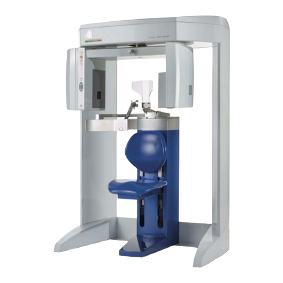
BACK PLATE SUPPORT KNOB (SLIDES TO ADJUST THE POSITION OF THE GATE HEAD SUPPORT) (SWINGS OPEN, MAGNETS LOCK IN PLACE) MOTORIZED CHAIR (MOVES UP/DOWN VIA BUTTONS ON GANTRY CONTROL BOX) ® KaVo 3D eXam Imaging System k990400 September 19, 2007... -
Page 10: Major System Items
Kavo 3D eXam ® Operators’ Manual The system consists of a Gantry and Computer Workstation. In order for the system to operate, both the Gantry and Computer Workstation must be turned ON. The system captures data for 3D Skull Reconstruction for the... -
Page 11: Conventions Used In The User Manual
Introduction Conventions Used in the User Manual Keyboard keys are represented in a font. • Bold For example, “Press .” Start Menu items and button names on the user interface display • are represented in a font. Bold For example, “At the Print window, click the button.”... - Page 12 Kavo 3D eXam ® Operators’ Manual Damage caused by any other abuse, misuse, mishandling, or • misapplication. Damage to acquisition computer, software, or operating • system caused by: o Additions or changes unauthorized by ISI o Viruses, spy ware, or gaming software...
-
Page 13: Chapter 2 - Safety Items
Chapter Safety Items Important Safety Information Imaging Sciences designs its products to meet stringent safety standards. However, to maintain the safety of Operators and Patients, you must operate the equipment correctly and properly and ensure the equipment is properly maintained. It is essential that you follow all safety instructions, warnings, and cautions specified in this manual to ensure the safety of Patients and operators. -
Page 14: Safety Precautions
Kavo 3D eXam ® Operators’ Manual Safety Precautions WARNING The X-ray unit may be dangerous to the Patient and operator if you do not observe and follow the safe exposure factors and operating instructions. Do not operate this system unless you have received training to perform a procedure. -
Page 15: Mechanical Hazards
Safety Items Mechanical Hazards WARNING Do not operate the system with any covers open or removed. Operating the system with open or removed covers could expose mechanical operating systems that could cause serious or fatal personal injury to you or the Patient. Only qualified and authorized service personnel should remove covers from the system. -
Page 16: Emergency Stop
Kavo 3D eXam ® Operators’ Manual Emergency Stop This manual contains instructions for safe operation of this dental X- ray System. In the event of an emergency (any moving component collides with any parts of the equipment or items in the environment,... -
Page 17: Interlock System
Safety Items When using this method; ensure that the factory installed NOTE: jumpers between terminals 3 & 5 and 4 & 6 are in place. These jumpers should only be removed when an interlock system is used. Interlock System This System is equipped with provisions for an Interlock Circuit which, when opened, will turn off X-ray power. -
Page 18: System Labels
Kavo 3D eXam ® Operators’ Manual System Labels The following labels are attached to the system. k990400 September 19, 2007... -
Page 19: Chapter 3 - System Controls And Indicators
Chapter System Controls and Indicators Controls and Indicators are found on the following system units: Main Control Box • Patient Alignment Panel • Patient Emergency Stop Control • System Status Indicators • Main Control Box ON powers the Gantry and the POWER indicator lights to show that the Gantry is ON. -
Page 20: Emergency Stop Control
Kavo 3D eXam ® Operators’ Manual Emergency Stop Control EMERGENCY STOP allows the Patient to halt all X-ray and scanning activities by pressing the button. The Emergency Stop Control can either be hung from the head support mechanism or held in the Patient’s hand as desired. -
Page 21: Chapter 4 - System Startup And Shutdown
Chapter System Startup and Shutdown System Startup The System includes a Gantry and a Computer Workstation. Both units must be ON to function properly. To start the system, do the following: 1. Power up Computer Workstation: press the power button on the front of the Workstation. The computer boots and loads the operating system. - Page 22 Kavo 3D eXam ® Operators’ Manual If changes were made to a case study, the following dialog box appears. a. Click Yes. The dialog box closes. b. .Click Create New Workup. c. Enter a name for new Workup in the Workup Name: field.
-
Page 23: Patient Information
Chapter Managing Patient Data Patient Information When i-CATVision is launched, the Patient Information window is displayed. This window lists all the Patients that were entered into the database. When a Patient is selected (highlighted), that Patient’s scanned images are listed in the window beneath the Patient List. Patients can be added or deleted and Patient Data can be edited as desired. -
Page 24: Add New Patient
Kavo 3D eXam ® Operators’ Manual Add New Patient To add a new Patient 1. From the Main menu, select File > New Patient. 2. Click Add . . . button. 3. Enter Patient data in the corresponding fields as applicable. -
Page 25: Edit Patient Details
Managing Patient Data (Although dates may be manually entered, it is recommended that the calendar tool be used in order to avoid data entry errors.) The Status drop-down list box indicates whether data has • been acquired for this Patient (by selecting the Done entry). 4. - Page 26 Kavo 3D eXam ® Operators’ Manual Done - Patient Data entered and scanned • Queued - Patient Data entered but not • scanned HIS/RIS - (Hospital Info System/Radiology • Info System) imported Patient Data PMS - (Practice Management System) •...
-
Page 27: Delete A Patient
Managing Patient Data Delete a Patient To delete an existing Patient: 1. From the Main menu, select File > New 2. If desired, limit the number of Patients listed by using the check boxes in the Show area at the lower right side of the dialog box. Only Patients whose data matches the selected criteria are displayed. -
Page 28: Hide/Display Patient List
Kavo 3D eXam ® Operators’ Manual Hide/Display Patient List The Patient List can be hidden by selecting Tools > Hide Patient from the Main menu. When hidden, the Patient list appears as shown below. To display the Patient list, select Tools > Show Patient from the Main menu. - Page 29 Managing Patient Data 2. If desired, limit the number of Patients listed by using the check boxes in the Show area at the lower right side of the dialog box. Only Patients whose data matches the selected criteria are displayed. Done - Patient Data entered and scanned •...
- Page 30 Kavo 3D eXam ® Operators’ Manual k990400 September 19, 2007...
-
Page 31: Chapter 6 - Acquisitioning (Scanning)
Chapter Acquisitioning (Scanning) Patient Positioning GANTRY CONTROL BOX HEAD (ADJUSTS CHAIR SUPPORT UP/DOWN) BACKPLATE HEAD SUPPORT CHIN BACK PLATE SUPPORT KNOB (SLIDES TO ADJUST THE POSITION OF THE GATE HEAD SUPPORT) (SWINGS OPEN, MAGNETS LOCK IN PLACE) MOTORIZED CHAIR (MOVES UP/DOWN VIA BUTTONS ON GANTRY... - Page 32 Kavo 3D eXam ® Operators’ Manual 3. Close Gate, making sure the magnet is secured in its locked position. 4. Use the Patient ALIGN buttons on the Alignment Control Panel to adjust the Patient Chair height. These controls allow movement of the Patient chair, up (Δ) and down (∇), to...
-
Page 33: Acquisitioning
Acquisitioning (Scanning) Tilt: Occlusal Plane Flat, Frankfur Plane tilted up slightly. Position of Alignment Lights for Full Head Scan: Horizontal: Occlusal plane between the lips. Vertical: 1.5 inches in front of condyle (chin support adjusted to CT acquisition position. 7. Make sure the Patient’s chin is stabilized in the chin support. 8. -
Page 34: Quick Picks
Kavo 3D eXam ® Operators’ Manual The Acquire window is displayed. 2. If desired, enter any remarks in the Study Remarks text field. 3. From the Quick Picks drop-down list box, select a standardized acquisition setup or create a new one (see details below). - Page 35 Acquisitioning (Scanning) 2 arches/anchor, 8.5 sec, 0.3 Voxel - recommended when • data is exported to implant planning software systems such as Nobel or SimPlant. Please check with your service to determine the desired height of the scan. Please be aware that most 3rd party software currently requires the scan to be taken at 0.4 Voxel resolution and no smaller.
-
Page 36: Volume Scan
Kavo 3D eXam ® Operators’ Manual b. Click the Delete button below the Quick Picks drop-down list box. c. A confirmation box is displayed, click Yes to delete. Volume Scan After the acquisition is launched and the Volume tab is selected, do the... -
Page 37: Preview, Dry Run, And Capture Scans
Acquisitioning (Scanning) time (reducing chance of movement), at a reduced radiation dose, with a Voxel Size that maximizes detail without the dataset being too large. It is recommended to use a faster Scan Time (for example, 5 sec.) for children, some elderly Patients (if movement is a significant issue), or if you require only a quick pan or TMJ Scan, or a secondary/follow-up scan (e.g. - Page 38 Kavo 3D eXam ® Operators’ Manual The following dialog box is displayed. 2. Click OK. The system proceeds to take a Static Exposure “Quick Ceph.” The resulting image is displayed on the screen. k990400 September 19, 2007...
- Page 39 Acquisitioning (Scanning) If the Horizontal & Vertical skull position looks correct, then proceed to the Volume scan. Otherwise, re-position the Patient or the volume center to achieve better positioning and restart this procedure. To ensure good quality, the required image should appear within a ¼...
- Page 40 Kavo 3D eXam ® Operators’ Manual Once the acquisition is complete, the machine rewinds. Wait until the machine rewinds before releasing the Patient from the machine. The software immediately begins the reconstruction of the image data. (The time required to reconstruct depends on the Scan Time and Voxel size selected.)
-
Page 41: Pan Scan (Optional)
Acquisitioning (Scanning) PAN Scan (Optional) A PAN scan is a scan mode that creates a Panoramic exposure that is a two dimensional image. Patient positioning is critical for PAN scans. The Gantry must also be properly aligned to ensure quality Patient images. Prior to performing a PAN scan, the Gantry alignment should be checked, to ensure optimal system performance. - Page 42 Kavo 3D eXam ® Operators’ Manual 2. Prepare the Bite Tip by inserting the narrow edges of white Bite Tip down into Bite Tip Holder uprights. Then turn the Bite Tip a 1/4 turn to lock into place. Narrow Edges...
- Page 43 Acquisitioning (Scanning) 6. From the Pan menu, make an Exposure selection: The Operator is required to determine the Patient’s head size. Small is normally selected for young children and small elderly females. Large is for a normal size adult or large child (head size).
- Page 44 Kavo 3D eXam ® Operators’ Manual WARNING The X-ray unit may be dangerous to the Patient and operator if you do not observe and follow the safe exposure factors and operating instructions. Do not operate this system unless you have received training to perform a procedure.
- Page 45 Acquisitioning (Scanning) 15. The PAN scan runs a few minutes and then displays the reconstructed image. 16. Adjust the Brightness/Contrast by dragging the cursor across the image (vertical/horizontal). k990400 September 19, 2007 6-15...
- Page 46 Kavo 3D eXam ® Operators’ Manual k990400 September 19, 2007 6-16...
-
Page 47: Chapter 7 - Reconstruction Of Anatomy
Chapter Reconstruction of Anatomy Preview Screen Once Patient data is acquired or data for a Patient is loaded, the iCATVision software immediately reconstructs the Patient anatomy images. (User modified Patient data, referred to as a Workup, can also be loaded to the preview screen. While data loading is occurring, a preview window appears in the center of the screen. - Page 48 Kavo 3D eXam ® Operators’ Manual Once data is successfully reconstructed, the Preview screen appears as shown below, showing the Panoramic, Sagittal, Coronal, and Axial views of the skull through midline. PATIENT DATABASE PATIENT IMAGES PANORAMIC VIEW PATIENT DETAIL SAGITTAL...
-
Page 49: Adjusting The Panoramic View
Reconstruction of Anatomy Patient Images lists all images that pertain to the selected (highlighted) Patient from the Patients in Database list. Patient Detail View shows detailed Patient data, including acquisition details, for the currently selected Patient workup (highlighted in the Patients in Database list). -
Page 50: Contour Line Setup
Kavo 3D eXam ® Operators’ Manual 4. Then move the next two points closer to the molars. See the example below. Any changes made are reflected in the Panoramic View. Contour Line Setup Contour Lines are used to mark the Maxilla and Mandible in the Sagittal and Coronal Views on the preview screen. - Page 51 Reconstruction of Anatomy One or both Contour Lines can be added/removed from the Sagittal and Coronal Views on the preview screen. To do this, do the following: 1. On an image view on the Preview screen, right-click and select Add/Remove Contourline. 2.
-
Page 52: Removing Circumference Artifacts
Kavo 3D eXam ® Operators’ Manual Removing Circumference Artifacts Circumference Artifacts are displayed in the Preview Screen as horizontal lines in the Coronal and Sagittal views and a white partial circle around the Axial View. This artifact can be removed from the dataset by right clicking the Preview Screen and selecting Remove Stray Voxels from Circumference. -
Page 53: Selecting Mip Or Radiograph Display
Reconstruction of Anatomy Selecting MIP or Radiograph Display The system software enables displaying images as MIP or Radiograph. To select the type of image displayed: 1. Move cursor to the top right of any of the image views on the preview screen. -
Page 54: Zoom Feature
Kavo 3D eXam ® Operators’ Manual Zoom Feature Most views allow zooming in and out to view more or less detail for the displayed image. To use the zoom feature: 1. Move the cursor to the bottom right of the image in which you wish to use the zoom function. - Page 55 Reconstruction of Anatomy Setting Filters for a Single Image To change the filter setting for an individual image: 1. Right-click the image and select Set Filter > and select desired filter setting. The selected filter setting is applied to the corresponding image.
-
Page 56: Taking Measurements
Kavo 3D eXam ® Operators’ Manual Resetting all Filters to the Default Values To reset filters to the default values: 1. From the Main menu, select Tools > Filter Settings > Reset To Default. 2. Click Yes. The dialog box closes and all filter settings are set to the default. - Page 57 Reconstruction of Anatomy 3. Repeat steps 2 and 3 to take additional measurements. A maximum of four HU measurements can be taken at a time in a normal view and two in a cross section view. Additional measurements are displayed in varying colors so that they can be easily associated with the selected image area.
-
Page 58: Distance
Kavo 3D eXam ® Operators’ Manual To remove a specific measurement: 1. Right-click the measurement that is to be removed. 2. Select Remove Measurement from the popup menu. Remove All Measurements - removes all measurements from selected view. Inactivate All Measurements - grays out all measurement indicators and removes the measurements from the selected view. - Page 59 Reconstruction of Anatomy The menu closes and the cursor changes to the distance measurement symbol. 2. Click, drag, and click to define the measurement. Measurement statistics appear in the upper left corner of the image. 3. Repeat steps 2 and 3 to take additional measurements. A maximum of nine distance measurements can be taken at a time in a normal view and four in a cross section view.
-
Page 60: Rotating Views
Kavo 3D eXam ® Operators’ Manual To switch off the distance cursor: 1. Right click the image and select Distance. The cursor reverts to the default cursor. 2. Measurements can be selectively removed from a view as desired. All measurements can also be deactivated/reactivated for a view. - Page 61 Reconstruction of Anatomy 2. Using the rotation tool, click and drag to rotate the selected image. A grid appears over the selected image to provide a reference for rotation. 3. After the selected image is rotated, release the mouse. The grid is no longer present.
-
Page 62: Saving Views As Jpeg Image Files
Kavo 3D eXam ® Operators’ Manual Saving Views as JPEG Image Files Data in any view in iCATVision can be saved as a JPEG image file. To save view as a JPEG Image File: 1. Right click the image and select Save as JPEG. - Page 63 Reconstruction of Anatomy 2. Then do one of the following: a. Click Create New Workup. b. Enter a name for the new workup in the Workup Name: field. c. Click OK. The dialog box closes and the new workup is displayed on the Select a Workup dialog box.
-
Page 64: Load An Existing Workup
Kavo 3D eXam ® Operators’ Manual If you made or changed a workup and attempt to close the iCATVision software or switch to a different Patient, the following dialog box appears. To save the changes made, click Yes. The Select a Workup dialog box appears. -
Page 65: Delete An Existing Workup
Reconstruction of Anatomy Delete an Existing Workup To delete an existing workup: 1. Right-click any image on Preview screen and select Save This Workup. 2. Right-click the Workup to delete. k990400 September 19, 2007 7-19... - Page 66 Kavo 3D eXam ® Operators’ Manual 3. Click Yes. The dialog box closes and the selected Workup is deleted. 4. Click Cancel to close the Select a Workup dialog box. k990400 September 19, 2007 7-20...
-
Page 67: Chapter 8 - Detail Screens
Chapter Detail Screens Preview Screen All Detail Screens are accessed via double-clicking a corresponding view on the Preview Screen. PANORAMIC VIEW SAGITTAL VIEW CORONAL VIEW AXIAL VIEW Panoramic View - double-click displays the Implant • Planning Screen. Sagittal View - double-click displays the Ortho (Ceph) •... -
Page 68: Implant Planning Screen
Kavo 3D eXam ® Operators’ Manual Implant Planning Screen Double-click the Panoramic View on Preview Screen displays the Implant Planning Screen. The Implant Panning Screen is divided into four main viewing areas: Axial Slice Position View (upper left) used to adjust the •... - Page 69 Detail Screens Patient position indicators are used on the Implant Planning Screen to indicate the orientation of the displayed data. These are: R = Right Side P = Posterior B = buccal To use the Implant Panning Screen: 1. Click and drag the blue dots on the axial slice position view to adjust the image displayed on the panoramic map view.
- Page 70 Kavo 3D eXam ® Operators’ Manual The cross section views are located as indicated by the hash marks displayed in the axial slice position view. If the 0.00 position is displayed, it is outlined in red. All slices to the patient’s right side are displayed as negative numbers.
- Page 71 Detail Screens c. Drag the O in the center of the diagonal toolbar to adjust the pan focal trough. d. Drag the O in the center of the vertical toolbar (right side of view) up or down to change the height of anatomy viewed in the cross section views.
-
Page 72: Ortho Screen
Kavo 3D eXam ® Operators’ Manual Ortho Screen Double-clicking the Sagittal View on the Preview Screen displays the Ortho (Ceph) Screen. The Ortho screen displays the Lateral Cephs in Radiographic and MIP mode as well as a Coronal View in MIP mode, all at the thickness of the volume. -
Page 73: Mpr Screen
Detail Screens To remove the airway information from the View, right click the airway view and select Untag Airways. MPR Screen Double-click Coronal View on Preview Screen displays MPR Screen. The MPR Screen allows you to scroll through the Axial (upper left), Sagittal (upper right), and Coronal (lower left) slices. - Page 74 Kavo 3D eXam ® Operators’ Manual To use the MPR Screen: 1. Drag center (O) tools from any view to move the slice location. The views are colored coded to correlate to which view is adjusted by which tools. 2. Drag the solid circle tool (to the right for horizontal toolbars; on the bottom for vertical toolbars) to adjust the slice thickness of the corresponding color coded view.
- Page 75 Detail Screens 2. Drag to position the linear slice as desired. The resulting slice is displayed in the view at the lower right of the MPR Screen. 3. To reposition the line, drag the end points of the line. To explore additional cut planes in an animated (consecutive) fashion: 4.
- Page 76 Kavo 3D eXam ® Operators’ Manual 5. Drag to position the cut planes slice as desired. Cursor changes to a film icon. 6. Right-click image. and select Explore Speed 7. Enter desired animation speed in Movie Playback Speed field. 8. Click OK.
-
Page 77: Tmj Screen
Detail Screens TMJ Screen Double-click Axial View on Preview Screen displays TMJ Screen. TMJ Screen enables condyle mapping and creating corresponding coronal slice views. To use the TMJ Screen: 1. If necessary, pan the Axial (SMV) View (upper left) down in the window to see the condyles. - Page 78 Kavo 3D eXam ® Operators’ Manual 3. Drag center (O) tools from the RIGHT and/or LEFT CONDYLE WINDOWS to move the slice locations of the cross section views. 4. Drag the solid circle tool (right of toolbars) to adjust the slice thickness of the cross section views.
-
Page 79: Chapter 9 - Tools
Chapter Tools DICOM Database and DICOM Export Setup The next procedure describes how Patient Data is converted into DICOM images. This procedure is used to determine where these DICOM image files are to reside. 1. From the top Main menu, select Tools > Setup. DICOM Database Root Folder - contains patient data that •... -
Page 80: Dicom Import Controls
Kavo 3D eXam ® Operators’ Manual 2. Click Browse for both fields. 3. Choose a path for the DICOM Database Root Folder and the Export DICOM Destination Folder. If required, click Make New Folder. 4. Click OK. DICOM Import Controls This feature is not presently used. -
Page 81: Export Dicom
Tools The Read/Write Access Test Dialog window is displayed. 2. Ensure that all tests have passed. Click OK to close. Export DICOM DICOM (Digital Imaging and Communications) in Medicine, is an industry standard for digital images which is a means for medical imaging products to share images. -
Page 82: Create Cd
Kavo 3D eXam ® Operators’ Manual Multi-File DICOM - a separate file for each image slice, • resulting in many small files. Some earlier model viewers require this format. Compressed - files are compressed to save space (smaller • file size) Uncompressed - files are converted to DICOM and stored •... -
Page 83: Erase Cd-Rw
Tools Select desired Output Selections. Single File DICOM - one large image file (recommended) • Multi-File DICOM - a separate file for each image slice, • resulting in many small files. Some earlier model viewers require this format. Compressed - files are compressed to save space (smaller •... -
Page 84: Reporting
Kavo 3D eXam ® Operators’ Manual 3. Choose a path for the Export DICOM Destination Folder. If required, click Make New Folder. 4. Click OK. Reporting Patient reports are generated by inserting patient images into a single or multiple page document. Patient information and text notes can also be inserted as required. -
Page 85: Create New Report
Tools 1. Click (highlight) a patient from the Patient List. Allow time for the Patient Image to load. 2. From the Main menu, select Tools > Reporting. 3. Click Run Report from the Options box. 4. Use the Browse button to locate a report to Run. Create New Report To create a new Patient Report: 1. - Page 86 Kavo 3D eXam ® Operators’ Manual 6. Select required parameters and click OK. Number of Images Single Images – used to select images within iCATVision • or from a file (select FILE) Images in Range – used to select specific cross sections •...
- Page 87 Tools The Image Properties box can be displayed at any time by right- clicking inside the image box and selecting Properties. 7. Images can be repositioned or sized by clicking the image and then holding down left mouse button and dragging the cursor. Cross Arrows –...
- Page 88 Kavo 3D eXam ® Operators’ Manual Double click an existing Text box to display the Text Container Properties box. 12. Images can be repositioned or sized by clicking the image and then holding down left mouse button and dragging the cursor.
-
Page 89: Modify Existing Report
Tools 16. Select required parameters and click OK. Toolbars The toolbar at the top of the screen can be used to manipulate the text, scroll through pages and preview the report. Modify Existing Report This function is used to edit reports that were previously created. To create a new Patient Report:. - Page 90 Kavo 3D eXam ® Operators’ Manual k990400 September 19, 2007 9-12...
-
Page 91: Chapter 10 - Calibration And Quality Assurance
Chapter Calibration and Quality Assurance The Panel and Geometry Calibrations can be conducted by the Owner / Operator of the device. It is recommended that the Panel Calibration be performed once a week. Panel Calibration The Panel Calibration runs in both Portrait and Landscape positions. The entire calibration takes about 8 to 10 minutes to complete. - Page 92 Kavo 3D eXam ® Operators’ Manual 4. Click OK to close Patient Information box. 5. Click the Calibration tab. 6. Click the Panel Calibration button (bottom button). A window is displayed “Remove all objects from the field of view and click OK to start X-ray exposure.”...
-
Page 93: Geometry Calibration
Calibration and Quality Assurance Geometry Calibration The Panel Calibration must be performed prior to running the Geometry Calibration. It is recommended to run the Geometry Calibration once a year or if image quality becomes degraded. The Geometry Calibration also runs in both Portrait and Landscape positions and takes about 12 to 15 minutes to complete. - Page 94 Kavo 3D eXam ® Operators’ Manual 18. The BB Phantom image is displayed, shown below. Front Back (Volume Center) (Volume Center) 19. Ensure that the phantom is centered, level, and all BBs (dots) appear in the FOV. If required, make adjustments and click Preview again.
- Page 95 Calibration and Quality Assurance 22. The Geometry Calibration scans both Landscape and Portrait Modes. PORTRAIT SCAN LANDSCAPE SCAN Metal Platform Support (below FOV) Ensure that the metal platform support is below the Field of NOTE: View (as shown above.) 23. Calibration progress is displayed on the bottom of screen. Ensure that all beads are detected and valid in both scans.
-
Page 96: Qa Phantom Test
Kavo 3D eXam ® Operators’ Manual QA Phantom Test The following Quality Assurance Tests can be conducted by the Owner / Operator of the device. It is recommended that the System Quality Assurance be performed annually or if image quality becomes degraded. - Page 97 Calibration and Quality Assurance 4. Center the QA Phantom on the platform with the Air Hole positioned at the left rear of the Gantry (shown below). AIR HOLE ACRYLIC TEFLON LDPE 5. Start the test by selecting File > New Patient from the Main menu.
- Page 98 Kavo 3D eXam ® Operators’ Manual 11. As shown below, the Phantom Platform must appear below the Field of View and the Phantom must be centered. 12. Adjust the Phantom Platform to achieve the proper height. 13. To move the phantom to the right or left, use the Back / Front feature on the Volume tab and then return to the Calibration tab.
- Page 99 Calibration and Quality Assurance 17. The following preview screen is displayed. k990400 September 19, 2007 10-9...
-
Page 100: Line Pair Evaluation
Kavo 3D eXam ® Operators’ Manual Line Pair Evaluation 18. Access the QA Test images for evaluation by double clicking Coronal View. (bottom image, 3 from the left). 19. The image below is displayed. In the upper right corner view, slide the Vertical and Horizontal lines to the Line Pairs centers as shown below. -
Page 101: Distance Measurement Test
Calibration and Quality Assurance 22. Adjust Brightness and Contrast level for the best image quality. Evaluate the image. Line Pair - Line Pairs consists of a resolution of 10 lines per cm (5 dark wish 5 light). Line Pairs 10 through 16 are displayed in image (shown above). -
Page 102: Hounsfield Unit (Hu) Measurements
Kavo 3D eXam ® Operators’ Manual Hounsfield Unit (HU) Measurements This procedure checks consistency in various measurements. The positioning and dimension of each Region of Interest (ROI) is very important. Be consistent between each assessment to achieve the minimum deviation. - Page 103 Calibration and Quality Assurance d. Move the position of the slice to the middle of the phantom as shown in the figure. 29. Right click the image and select HU Statistics from the menu. 30. Area of ROIs should be at least 40mm but less than 46mm Use the Region Tool to define a ROI in the center of each circle of material implanted within the QA phantom.
-
Page 104: Qa Water Phantom Test
Kavo 3D eXam ® Operators’ Manual QA Water Phantom Test The Water Phantom Test is a noise level test. The HU measurements are taken at five different regions in the Water volume. 1. Remove Chin Cup and insert Phantom Platform. - Page 105 Calibration and Quality Assurance 10. The white dotted line, in the preview screen, is use to set the water height. The line should appear near the middle of the water height. Adjust the Phantom Platform to achieve the proper height. Use the menu Back/Front arrow-slide to adjust the phantom side-to- side position.
- Page 106 Kavo 3D eXam ® Operators’ Manual 13. The red dotted line, in the upper right screen, should appear in the middle of the water height. Use the Center Line Positioning tool to make the height adjustment. k990400 September 19, 2007...
-
Page 107: Noise Level Test
Calibration and Quality Assurance Noise Level Test 14. Zoom the Axial image (upper left). To zoom, start at the lower right corner of the image and drag the cursor across the image. 15. Right click the image and select HU Statistics from the menu. Use the Region Tool to define a ROI (Region of Interest) in the center of Water and also the Air (outside area of the water bowl), as shown above. -
Page 108: Uniformity Test
Kavo 3D eXam ® Operators’ Manual Uniformity Test 18. Use the Noise Level Test dataset (previous procedure), if not available, perform steps 1 to 13. If using the Noise Level Test, right click the HU data (upper right corner of image) and select Remove all measurements. - Page 109 Calibration and Quality Assurance The HU Area (box size) should be approximately 400.0 mm 20. Note and record the Mean and SD values of the four regions. See chart below. 21. After recording values, a fifth ROI is required from the center of the water area.
-
Page 110: Pan Phantom Test
Kavo 3D eXam ® Operators’ Manual PAN Phantom Test PAN Phantom Test is used to validate the PAN scan data capture. To perform a PAN Phantom Test: 1. Prepare the Bite Tip by inserting the narrow edges of the Bite Tip down into the Bite Tip Holder uprights. - Page 111 Calibration and Quality Assurance 8. Click OK to close the Patient Information box. 9. Click the Pan tab in the Acquisition window and select, Exposure: Large 10. Click the Capture button to start the test. 11. The system moves approximately 1/4 rotation to the Home Position and then displays the scan parameters.
- Page 112 Kavo 3D eXam ® Operators’ Manual 13. The PAN scan runs a few minutes and then displays the reconstructed image. 14. Adjust the Brightness/Contrast by dragging the cursor across the image (vertical/horizontal). All seven metal balls should become visible as shown below.
-
Page 113: Radiation Output Test
Calibration and Quality Assurance Radiation Output Test It is recommended that a check of the kVp and Radiation Output of the X-ray source be performed annually by a qualified Physicist. The incident Absorbed Dose at the detector may be measured using a dosimeter. -
Page 114: Interpretation
Tube Output (μGy/mAs) =Dose at Detector x (Source to detector distance) Displayed mAs ® Where Source to detector distance = 0.68m for the KaVo 3D eXam Declaration of Conformity Manufacturer and Technical File Holder: European Representative: Imaging Sciences International... - Page 115 Calibration and Quality Assurance meets or exceeds all Imaging Sciences International published specifications. The test equipment used to test and calibrate the equipment listed above is regularly calibrated against company standards that are directly traceable to National Institute of Standards Technology. The equipment has also been tested and/or evaluated against and found compliant to the following standards/requirements: UL 60601-1 IEC/EN 60601-1-4...
-
Page 116: Equipment Class Determination
Kavo 3D eXam ® Operators’ Manual Equipment Class Determination The equipment class was determined by reviewing the Essential Requirements of the European Union Council Directive concerning Medical Devices 93/42/EEC, Annex 9, rule 10, Food and Drug Administration (FDA) 21CFR part 860, Canadian Medical Devices Regulations (CMDR), schedule 1 and Health Canada “Medical... -
Page 117: Chapter 11 - Radiation Environment Survey
Chapter Radiation Environment Survey The useful and scattered beams can produce serious bodily injuries to Patients and persons in the surrounding area. Adequate precautions must always be taken to avoid or reduce exposure to the useful beam, as well as scattered radiation. Refer to the following figure and related table to determine scattered beam measurements. -
Page 118: Conditions Of Operation - 9 And 27 Second Scans
Kavo 3D eXam ® Operators’ Manual Conditions of Operation – 9 and 27 Second Scans All data was acquired using Victoreen Model 450P Survey Meter (S/N 3159) in integrate mode. The data was acquired in concentric circles of radii listed in table below A lab head phantom was placed within the beam to act as the scattering agent. - Page 119 Radiation Environment Survey Total scan time: 27 seconds Distance in Feet Exposure Exposure scans/wk scans/wk scans/wk Location [meter] (μR) mR/wk mR/wk mR/wk 3 [0.91m] 0.24 2.40 6.00 12.00 6 [1.82m] 0.07 0.70 1.75 3.50 9 [2.74m] 0.037 0.37 0.93 1.85 3 [0.91m] 0.28 2.80...
-
Page 120: Recommended Operating Requirements
Kavo 3D eXam ® Operators’ Manual Recommended Operating Requirements Local agencies or government bodies or international standards may dictate different and/or additional requirements for installation of the system in order to protect personnel and the public from exposure from the radiological output of the device. Consult your local agencies, government bodies, or international standards for actual requirements which apply. -
Page 121: Dose And Imaging Performance Information
Radiation Environment Survey An annual radiation survey may be typically required. This • survey is typically required to be submitted to the local agency or government body. A phantom or patients may be used for system training. • Employees of the facility may not be used for this training. The system shall be registered with the local agency or •... -
Page 122: Measurements
Kavo 3D eXam ® Operators’ Manual (f) appropriate to the task at hand to convert exposure (R) to absorbed dose (rad): 0.78 rad/R for comparison to FDA-required, manufacturer-reported data (Lucite), and this is also appropriate for acrylic 0.93 or 0.98 rad/R for patient dose estimates (tissue or water) 0.87 rad/R for calculation of, or comparison to, CTDIw... -
Page 123: Sensitivity Profile
Radiation Environment Survey Sensitivity Profile For the ultra high resolution mode when the bead SIZE in the phantom is scanned the following sensitivity profile is obtained. Hounsfield value -2752 -3104 -2560 3104 20352 24928 14496 2528 -1888 -2368 -2560 k990400 September 19, 2007 11-7... -
Page 124: X-Ray Tube Assembly
Kavo 3D eXam ® Operators’ Manual X-ray Tube Assembly Imaging Sciences International utilizes the SXR 130-15-0.5 X-ray Tube to manufacture our X-ray head assemblies. Operator Data Available focal spot sizes (mm): 0.5 Available target angles: 15° Anode construction: Vacuum cast copper with... - Page 125 Radiation Environment Survey EMISSION CHARACTERISTICS (Full Wave Rectified, Sige Phase, Bi-polar) 70 kVp 100 kVp 90 kVp 130 kVp TUBE CURRENT (mA) FILAMENT VOLT/AMP HARACTERISTICS: 60 Hz AC & DC ANOD OOLING CURVE ANODE HEAT STORAGE CAP 30000 H.U. MAX. ANODECOLING RATE 165 H.U.
- Page 126 Kavo 3D eXam ® Operators’ Manual k990400 September 19, 2007 11-10...
-
Page 127: Chapter 12 - General Product Information
Chapter General Product Information Technical Specifications X-ray Source: Tube Voltage: 120 kVp Tube Current: 3-7 mA Voltage Wave Shape: Constant Potential Focal Spot: 0.0197 inches (0.5 mm) Duty Cycle: Source to Sensor distance: 28.1 inches (71.4 cm) Source to Patient distance*:19.5 inches (49.53 cm) (center of rotation) * The patient must be properly positioned in the Head Support Positioner Mechanism for each patient for all applications in order to have the focal spot to skin distance as large as possible. -
Page 128: Power Requirements
Kavo 3D eXam ® Operators’ Manual Image Detector: Amorphous Silicon Flat Panel (readable area), 9.37” width x 7.56” height (23.8 cm width x 19.2 cm height) Sensor Front Panel Attenuation Value: Less than 1mm of aluminum equivalent Gray Scale: 14 bit Voxel Size: 0.4/0.3/0.25/0.2 mm... -
Page 129: Environmental Specifications
General Product Information Environmental Specifications Operating 50 to 95 degrees Fahrenheit (10 to 35 degrees Celsius) 45% to 75% humidity Transportation and Storage 32 to 104 degrees Fahrenheit (0 to 40 degrees Celsius) 30% to 80% humidity Acquisition Computer Minimum Specifications for Acquisition Computer Provided with the System: Pentium-4 Processor, 3.8 GHz minimum •... -
Page 130: Patient Support Chair
Kavo 3D eXam ® Operators’ Manual Patient Support Chair Overall dimensions: 28.5"d x 24”w x 43”h (72.4 cm x 61 cm x 109.2 cm) Weight: 125 lbs (56.7 kg) Seat height adjustment: 14” to 29” (35.65 cm to 73.7 cm) -
Page 131: Electromagnetic Or Other Interference (Emissions And Immunity)
General Product Information Electromagnetic or other Interference (Emissions and Immunity) The System was tested and found to comply with the limits for Class B equipment, pursuant to IEC 60601-1-2. These limits are designed to provide reasonable protection against harmful interference in a commercial environment. The system generates, uses, and can radiate electromagnetic energy and if not installed and used in accordance with these instructions, may cause harmful interference to surrounding equipment. - Page 132 Kavo 3D eXam ® Operators’ Manual The System is intended for use in an electromagnetic environment specified below. The Customer or User should ensure that the system is used in such an environment. Radiated RF The 17-19 Imaging System is intended for use in an...
-
Page 133: Equipment Standards
General Product Information Consult Imaging Sciences International, the dealer or an • experienced technician for help. Use only the interface cables provided with the System. Using other interface cables may exceed the limits of Class B equipment, pursuant to IEC 60601-1-2. Equipment Standards The System was tested and/or evaluated against and found compliant to the following standards/requirements:... -
Page 134: Preventive Maintenance Schedule - For Owner / User
Kavo 3D eXam ® Operators’ Manual Preventive Maintenance Schedule - for Owner / User Daily: Routine Dusting - all surfaces Monthly: Clean all surfaces and check for failed/faulty indicator lights Yearly: Check for satisfactory film density IT IS THE RESPONSIBILITY OF THE USER TO INSURE THAT... -
Page 135: Preventive Maintenance Schedule Table
General Product Information Preventive Maintenance Schedule Table Assembly / Component MONTHS TEST INSPECT Tube Housing Assembly Certification Label Warning and Indicators Oil Leaks Physical Damage Mounting System Stability Beam Limiting Device Physical Damage Certification Label X-Ray Controller Timer Line Voltage Calibration Exposure Switch and Cord Line Switch... -
Page 136: Replaceable Parts - Reference List
Kavo 3D eXam ® Operators’ Manual Replaceable Parts - Reference List Sub Assembly Number Description 11-0 Rotation Stepper Motor 27-0 Head Rest, Carbon Fiber 35-0 Tube Head Assembly 102-16 Platform Motor 109-2 Receptor Motor 137-0 Beam Limiter Assembly 1000-0 X-ray Power Supply Assembly... -
Page 137: Accessories
General Product Information Accessories Item Description Part Number Quantity Door Interlock Cable 1524 Warning Cable 1527 Patient E-stop 1304-0 E-net Cable 50 1000116 Tool Kit Foot Stool 1000197 Booster Seat 1000196 Glide 1000179 Control Box 1306-0 Chair Patch Cable 1520 Cable Clips 101-6 Head Rest... -
Page 138: System Gantry Dimensions
Kavo 3D eXam ® Operators’ Manual System Gantry Dimensions TOP VIEW FRONT VIEW SIDE VIEW k990400 September 19, 2007 12-12... -
Page 139: Appendix A - Three Dimensional Volume Rendering (3Dvr)
Chapter Three Dimensional Volume Rendering (3DVR) Open Database 3 DVR is a standalone program which runs independently and is not part of iCATVision. 1. To open DVR (Diagnostic Volume Rendering,) double click the DVR icon. The Program Main menu is displyed. k990400 September 19, 2007... - Page 140 Kavo 3D eXam ® Operators’ Manual To get started, an image dataset must be loaded. The case MUST be in DICOM format. If importing a case from iCATVision, make sure to export the case in DICOM3- Multi File format. 2. Click Open Dataset, a browse window is displayed.
-
Page 141: Axial Functions
Axial Functions There are 5 tools under Axial Functions. Paging • W/L (Window Level) • ROI (Region of Interest) • Distance • Identify • Paging Paging is the tool that allows for scrolling through all the axial slices of the dataset. Notice at the top of the DVR window, the axial slice number currently displayed is next to the word DVR. -
Page 142: Roi (Region Of Interest
Kavo 3D eXam ® Operators’ Manual ROI (Region of Interest) ROI is a tool used for determining Hounsfield Units. To activate the ROI tool: 1. Click ROI Radio button. 2. Drag cursor to create a box around region of interest. Release the mouse button to move box, then click again to complete the box. -
Page 143: Distance
Distance The distance tool measures linear distance. To activate Distance tool: 1. Click Distance radio button. 2. Drag cursor from point to point to create a measurement line (see below in green). Linear measurement is displayed in millimeters (upper left corner.) k990400 September 19, 2007... -
Page 144: Identify
Kavo 3D eXam ® Operators’ Manual Identify The Identify tool identifies areas of interest at different densities. It is defaulted to detect the most dense anatomy or material. This tool is often used to remove a piece of anatomy from the image. - Page 145 Display the slice range of interest: 4. On the Axial screen, drag the cursor either UP or DOWN to scroll through the axial slices. Dragging the cursor upward scrolls towards the top of the skull and ragging downward scrolls towards the bottom of the skull. On the 3DVR Setup screen, select a CT Range (1 to 4).
-
Page 146: Hounsfield Unit Calibration Offset
Kavo 3D eXam ® Operators’ Manual Hounsfield Unit Calibration Offset Before proceeding to the View Volume functions, first enter a calculated offset into the General Setup for Hounsfield Units. The value that is required is based on the RIO function. -
Page 147: View Volume
6. Enter Calculation Offset which currently has a value of 0. 7. Click OK. View Volume View Volume allows viewing all 3 projections of the 3D data: Axial, Coronal and Sagittal. Also enables the creation of 3D Renderings. Enable View Volume Tools, click the View Volume button. k990400 September 19, 2007... -
Page 148: Projection Type
Kavo 3D eXam ® Operators’ Manual Projection Type Projection Type enables viewing 3D data in 2 different projections or modes: Radiographic and MIP. Radiographic mode - The above example has • Radiographic mode enabled. The Axial, Coronal, and Sagittal views are all in Radiographic mode. -
Page 149: Volume Edit
Volume Edit Volume Editing is used to select an area of interest to create a 3D rendering. The two methods used are Box and Freehand. Box - with this option, each of the 3 views are displayed • with a red box around the data. Boxes can be resized to select different areas of interest. -
Page 150: Vr Functions
Kavo 3D eXam ® Operators’ Manual VR Functions VR Functions (Volume Rendering) is a tool used for selecting the type of 3D image to create. To Create a 3D Image: 1. From the first View drop-down menu select a direction to display. The choices are: AP (Anterior Posterior) •... - Page 151 Remember that the 3D data is calculated using the boxed NOTE: or freehand selected areas of interest in the Axial, Coronal & Sagittal views. In this sample, the entire volume data is selected in all 3 views. Below is a sample of a 3D image calculated from the selected volume area seen below.
- Page 152 Kavo 3D eXam ® Operators’ Manual The 3Dimage can be rotated, enlarged or changed to another direction or type. These functions can be performed from the top right corner viewing area or you can choose to enlarge the 3D image to Full Screen (Right click on the 3D image and select View Full Screen).
-
Page 153: Pop Up Menu
Pop Up Menu Pop Up Menu contains the same VR Functions and also some additional functions. To access the Pop Up Menu, right click the 3D image. Save to JPG Saves full color 3D image in current working folder (adds .jpg extension). The current working folder is the folder opened from the Open Dataset. - Page 154 Kavo 3D eXam ® Operators’ Manual View Full Screen Full Screen displays the 3D image on the entire computer screen. All the same manipulation functions and 3D options are used in this display. Right click to display Pop Up menu to utilize functions.
-
Page 155: Appendix B - Icatvision & Icattransfer Installation
Chapter iCATVision & iCATTransfer Installation iCATVision ® iCATVision can be installed on any computer where iCAT images are viewed. We are pleased to provide iCATVision free of charge to ® anyone with access to iCAT scans with no limit on usage and the number of copies. -
Page 156: Install Icatvision
Kavo 3D eXam ® Operators’ Manual 3. On the server or central storage location, create another folder named iCATVision. 4. Under this iCAT Vision folder create a sub folder named iCATVision Root File structure on server/central storage location: If a server/central storage location is not available, then create ®... -
Page 157: Icatvision Setup
iCATVision Setup 1. From iCAT Vision select Tools > Setup. 2. Under DICOM Database Root Folder, browse to the iCAT Vision\ iCAT Vision Root and click OK. (This may be on the C: drive or on a networked drive). Setup is the same on all networked and non-networked computers or workstations. -
Page 158: Icattransfer
Kavo 3D eXam ® Operators’ Manual iCATTransfer ® iCATTransfer is not required for iCAT 17-19 Systems. NOTE: ® iCATVision is restricted to iCAT DICOM scans and necessitates an “authentication” of DICOM data (Digital Imaging Communications). Authentication is performed by a program called ®... -
Page 159: Icattransfer Passcode
iCATTransfer Passcode When iCATTransfer is first launched, it opens to the iCATTransfer Validation Screen (below). Instructions are displayed to send an email to Imaging Sciences at keys@imagingsciences.com with your customer information and the authentication code shown on screen. We will return an email with the Passcode to be entered into the iCATTransfer Validation Screen. -
Page 160: Configure Icattransfer
Kavo 3D eXam ® Operators’ Manual Configure iCATTransfer 1. Launch iCATTransfer, the following window is displayed. 2. Under Folder to Watch, Browse to iCATVision\ iCATVision Watch folder and select. (This is most likely on the C: drive of ® the iCAT Acquisition Computer). - Page 161 k990400 September 19, 2007...
- Page 162 Kavo 3D eXam ® Operators’ Manual k990400 September 19, 2007...
- Page 163 k990400 September 19, 2007...
- Page 164 Kavo 3D eXam ® Operators’ Manual k990400 September 19, 2007 B-10...
-
Page 165: Appendix C - Icatvision Quick Reference
iCATVision Quick Reference Navigating the i-CATVision Intrerface This guide shows how to: • View reconstructed images REMINDER • Use main features and tools to optimize an image Images are displayed as if you are looking at the patient from the front. TO DISPLAY PATIENT IMAGE Click Patient Name. -
Page 166: Suggestions For Adjusting Panoramic Map
iCATVision Quick Reference Suggestions for Adjusting Panoramic Map Start adjusting the Panoramic map from the Preview Screen. It is recommended to center the anterior point at midline and then move the next two points up closer to the anterior point on each side. Place them a few teeth away from anterior center. -
Page 167: Implant Planning Screen
Implant Planning Screen REMINDER Implant Screen is acquired by double clicking Panoramic View from Preview window. DISPLAYED VIEWS AXIAL SLICE POSITION PANORAMIC MAP 3D MODEL CROSS SECTIONS Center Slice is outlined in Blue. Slice Location Number Slice Location numbers start at “0” for center of anatomy or midline. -
Page 168: Axial Slice Position
iCATVision Quick Reference Panoramic Map PAN TOOLS Horizontal Tool Bar Drag this center tool left to right to move the slice location of the Cross Sections. The center slice is outlined in Blue on the Cross Sections. Drag the tool to the right to adjust the slice thickness of the Cross Sections. -
Page 169: Ortho Screen
Ortho Screen REMINDER Ortho Screen is acquired by double clicking Sagittal View from Preview window. DISPLAYED VIEWS The Ortho Screen displays the Lateral Cephs in Radiographic and MIP mode as well as a Coronal View and a Mid Sagittal Slice (15mm thick). -
Page 170: Install Case Studies From Cds
iCATVision Quick Reference TMJ Planning Screen REMINDER TMJ Planning Screen is acquired by double clicking Axial View from Preview window. DISPLAYED VIEWS TMJ Screen enables condyle mapping and creating corresponding coronal slice views. CURSOR TOOLS All views have Brightness/Contrast, Zoom and Pan. POP UP MENUS Right click to display the Pop Up menu to select:...
Need help?
Do you have a question about the 3D eXam and is the answer not in the manual?
Questions and answers