
Subscribe to Our Youtube Channel
Related Manuals for KaVo 3D eXam

Summary of Contents for KaVo 3D eXam
- Page 1 Operators’ Manual Cone Beam Volumetric Tomography and Panoramic Dental Imaging System K990400 16 April 2008...
- Page 2 Published by KaVo KaVo reserves the right to make changes to both this Manual and to the products it describes. Equipment specifications are subject to change without notice. Nothing contained within this manual is intended as any offer, warranty, promise or contractual condition, and must not be taken as such.
-
Page 3: What's New In This Release
What’s New in this Release Change Description Link to Topic Quality Control Frames added to Using Quality Control Frames on help access quality of captured scan. page 7-3 First and last frames of a scan can be compared to determine if patient moved during the scan. - Page 4 Kavo 3D eXam ® Operators’ Manual Change Description Link to Topic Gridlines added to MPR screen. MPR Screen on page 8-14 Scroll wheel on mouse is activated Implant Planning Screen on page to enable scrolling through slices on Implant Planning and MPR screens.
-
Page 5: Table Of Contents
Table of Contents ABLE OF ONTENTS What’s New in this Release ................1-1 Chapter 1 - Introduction System Description ...................1-1 Major System Items ..................1-2 About the Operators’ Manual .................1-3 Conventions Used in the User Manual .................. 1-3 Standard Limited Warranty ................1-4 Chapter 2 - Safety Items Important Safety Information .................2-1 Warnings, Cautions, and Notes .................... - Page 6 Table of Contents Chapter 4 - System Startup and Shutdown System Startup ....................4-1 System Shutdown .....................4-1 Chapter 5 - Managing Patient Data Patient Information ..................5-1 Hide/Display Study List ...................5-3 Delete Patient Scans ..................5-3 Add New Patient ....................5-4 Edit Patient Details ..................5-5 Access Patient Data ..................5-7 Delete a Patient ....................5-7 Chapter 6 - Acquisitioning (Scanning)
- Page 7 Table of Contents Rotating Views ....................7-18 Saving Views as JPEG Image Files ..............7-19 Saving and Loading Workups ...............7-19 Save a Workup ........................7-19 Load an Existing Workup ..................... 7-21 Delete an Existing Workup ....................7-22 Viewing and Reconstructing Raw Patient Scans ..........7-23 Chapter 8 - Detail Screens Preview Screen ....................8-1 Implant Planning Screen .................8-2...
- Page 8 Table of Contents Hounsfield Unit (HU) Measurements .................. 11-7 QA Water Phantom Test ................11-9 Noise Level Test ........................11-13 Uniformity Test ........................11-14 PAN Phantom Test ..................11-16 Radiation Output Test ..................11-19 Measured Dose ........................11-19 Interpretation ........................11-20 Declaration of Conformity ................11-21 Equipment Class Determination ..............11-22 Chapter 12 - Radiation Environment Survey Conditions of Operation –...
- Page 9 Table of Contents Disposal ......................13-4 Extension Cords .....................13-4 External Item ....................13-4 Cleaning ......................13-4 Electromagnetic or other Interference (Emissions and Immunity) ................13-5 Equipment Standards ..................13-7 Equipment Class ....................13-7 Preventive Maintenance Schedule - for Owner / User .........13-8 Planned Maintenance - 12 Month Schedule ..........13-8 Cleaning ..........................
- Page 10 Table of Contents Import Installation and Setup ...............15-2 Set Up DICOM Worklist Interface ..................15-2 Set Up Practice Management Interface ................15-4 Import Patient Data ..................15-5 Remote System Export ...................15-6 Export Installation and Setup ...............15-6 RSSM Log ......................15-8 Send Patient Data to a Remote System ............15-9 Appendix A - eXamVision Installation eXamVision .....................
- Page 11 Filtering Defaults ........................C-2 Removing Circumference Artifact ..................C-2 Saving and Loading Workups ....................C-2 Keyboard Shortcuts .........................C-2 Implant Planning Screen ................C-3 Panoramic Map ........................C-4 Axial Slice Position .........................C-4 Ceph Screen ....................C-5 MPR Screen ....................C-5 Install Case Studies from CDs ................ C-6 TMJ Planning Screen ..................
- Page 12 K990400 16 April 2008...
-
Page 13: Chapter 1 - Introduction
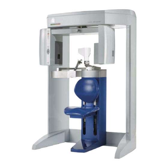
BACK PLATE SUPPORT KNOB (SLIDES TO ADJUST THE POSITION OF THE GATE HEAD SUPPORT) (SWINGS OPEN, MAGNETS LOCK IN PLACE) MOTORIZED CHAIR (MOVES UP/DOWN VIA BUTTONS ON THE SYSTEM CONTROL BOX) ® KaVo 3D eXa Imaging System K990400 16 April 2008... -
Page 14: Major System Items
Kavo 3D eXam ® Operators’ Manual The system consists of a Scanner and Computer Workstation. In order for the system to operate, both the Scanner and Computer Workstation must be turned ON. The system captures data for 3D Skull Reconstruction for the... -
Page 15: About The Operators' Manual
Introduction About the Operators’ Manual This documentation describes the safe and effective operation of the system. The information is intended to provide trained Technologists and Physicians the necessary guidance to operate the system in a safe and effective manner. Conventions Used in the User Manual Keyboard keys are represented in a font. -
Page 16: Standard Limited Warranty
The warranty period is not extended as a result of purchasing any additional parts from KaVo. The original purchaser must promptly notify KaVo in writing if there is a defect in material or workmanship. Written notice in all events must be received by KaVo before expiration of the warranty period. - Page 17 No oral or written information or advice given by KaVo, its agents or employees shall create a warranty or in any way increase the...
- Page 18 Kavo 3D eXam ® Operators’ Manual K990400 16 April 2008...
-
Page 19: Chapter 2 - Safety Items
Chapter Safety Items Important Safety Information KaVo designs its products to meet stringent safety standards. However, to maintain the safety of Operators and Patients, you must operate the equipment correctly and properly and ensure the equipment is properly maintained. It is essential to follow all safety instructions, warnings, and cautions specified in this manual to ensure the safety of Patients and Operators. -
Page 20: Safety Precautions
Kavo 3D eXam ® Operators’ Manual Safety Precautions WARNING The X-ray device may be dangerous to the Patient and Operator if you do not observe and follow the safe exposure factors and operating instructions. Do not operate this system unless you have received training to perform a procedure. -
Page 21: Mechanical Hazards
Safety Items Mechanical Hazards WARNING Do not operate the system with any covers open or removed. Operating the system with open or removed covers could expose mechanical operating systems that could cause serious or fatal personal injury to you or the Patient. Only qualified and authorized service personnel should remove covers from the system. -
Page 22: System Safety Devices
Kavo 3D eXam ® Operators’ Manual System Safety Devices Emergency Stops This manual contains instructions for safe operation of this dental X- ray System. In the event of an emergency (any moving component collides with any parts of the equipment or items in the environment,... -
Page 23: Sample Site Plan
Safety Items Sample Site Plan Below are two typical scanning room layouts that illustrate the system interconnect for the Warning System, Operator Control Box (Emergency Stop) and Interlock System which are all describe above. Warning System Cable 50 ft. [15.2m] (if used) Warning Light or Alarm... -
Page 24: Interlock And Warning System Schematic
Kavo 3D eXam ® Operators’ Manual Warning System Cable 50 ft. [15.2m] (if used) Patient Scanner Emergency Stop Box with Warning 10 ft. [3m] Cable Light or Alarm (not supplied) Hallway CAT 5 Ethernet Cable 50 ft. (15.2m) Computer Workstation... -
Page 25: System Labels
Safety Items System Labels The following labels are attached to the system. K990400 16 April 2008... - Page 26 Kavo 3D eXam ® Operators’ Manual K990400 16 April 2008...
-
Page 27: Chapter 3 - System Controls And Indicators
Chapter System Controls and Indicators Controls and Indicators are found on the following system units: Operator Control Box • Patient Alignment Panel • Patient Emergency Stop Control • System Status Indicators • Operator Control Box ON powers the Scanner and the POWER indicator lights to show that the device is ON. -
Page 28: Patient Emergency Stop Control
Kavo 3D eXam ® Operators’ Manual Patient Emergency Stop Control PATIENT EMERGENCY STOP allows the Patient to halt all X-ray and scanning activities by pressing the button. The Emergency Stop Control can either be hung from the head support mechanism or held in the Patient’s hand as desired. -
Page 29: System Startup
Chapter System Startup and Shutdown System Startup The System includes the Scanner and a Computer Workstation. Both units must be ON to function properly. To start the system, do the following: 1. Power up the Scanner: press the ON button on the Main Control Box. - Page 30 Kavo 3D eXam ® Operators’ Manual If changes were made to a case study, the following dialog box appears. a. Click Yes. The dialog box closes. b. Click Create New Workup. c. Enter a name for new Workup in the Workup Name: field.
-
Page 31: Chapter 5 - Managing Patient Data
Chapter Managing Patient Data Patient Information When Vision is launched, the Patient Information window is displayed. The Study List (shown below) lists all Patients that were entered into the database. When a Patient is selected (highlighted), that Patient’s scanned images are listed in the window beneath the Study List. - Page 32 Kavo 3D eXam ® Operators’ Manual from month 01 down to 12. Clicking Birth Date again reverses the order, displaying the 12th month first. This works with all headers for both the Patient and Scan Lists. Clicking Patient Name not only toggles the alphabetical order but can alter the listing to display the order of patients by First Name or by Last Name.
-
Page 33: Hide/Display Study List
Managing Patient Data Hide/Display Study List The Study List can be hidden by selecting Tools > Hide Study List from the Main menu. When hidden, the Study List appears as shown below. To display the Study List, select Tools > Show Study List from the Main menu. -
Page 34: Add New Patient
Kavo 3D eXam ® Operators’ Manual Add New Patient To add a new Patient 1. From the Main menu, select File > New Patient or right click an existing image from Patient Study list and select Acquire New Scan. 2. Click Add . . . button. -
Page 35: Edit Patient Details
Managing Patient Data Click the Birthdate drop-down to display the calendar tool. • Although dates may be manually entered, it is recommended that the calendar tool be used in order to avoid data entry errors. 4. Click OK to add Patient data. 5. - Page 36 Kavo 3D eXam ® Operators’ Manual Done - Patient Data entered and scanned • Queued - Patient Data entered but not • scanned HIS/RIS - (Hospital Info System/Radiology • Info System) imported Patient Data PMS - (Practice Management System) •...
-
Page 37: Access Patient Data
Managing Patient Data Access Patient Data Access Patient Details to be Scanned: 1. From the Main menu, select File > New Patient. 2. Highlight the Patient to be scanned and click OK or just double click the patient line. 3. The Acquisition screen is displayed for the selected patient. Delete a Patient To delete an existing Patient: Deleting a Patient does not delete any of the Patient’s scan... - Page 38 Kavo 3D eXam ® Operators’ Manual K990400 16 April 2008...
-
Page 39: Chapter 6 - Acquisitioning (Scanning)
Chapter Acquisitioning (Scanning) Patient Positioning PATIENT ALIGNMENT HEAD PANEL (ADJUSTS SUPPORT CHAIR UP/DOWN) BACKPLATE HEAD SUPPORT CHIN BACK PLATE SUPPORT KNOB (SLIDES TO ADJUST THE POSITION OF THE GATE HEAD SUPPORT) (SWINGS OPEN, MAGNETS LOCK IN PLACE) MOTORIZED CHAIR (MOVES UP/DOWN VIA BUTTONS ON PATIENT... - Page 40 Kavo 3D eXam ® Operators’ Manual 3. Close Gate, making sure the magnet is secured in its locked position. 4. Use the Patient ALIGN buttons on the Patient Alignment Panel to adjust the Patient Chair height. These controls allow movement of the Patient chair, up (Δ) and down (∇), to facilitate...
-
Page 41: Acquisitioning
Acquisitioning (Scanning) Tilt: Occlusal Plane Flat, Frankfort Plane tilted up slightly. Position of Alignment Lights for Full Head Scan: Horizontal: Occlusal plane between the lips. Vertical: 1.5 inches in front of condyle (chin support adjusted to acquisition position. 7. Make sure the Patient’s chin is stabilized in the chin support. 8. - Page 42 Kavo 3D eXam ® Operators’ Manual 3. If desired, enter any remarks in the Study Remarks text field. 4. Select a Resolution from the drop- down list box. In general, the lower the voxel size and the longer the scan time, the better the resolution and detail;...
-
Page 43: Preview, Dry Run, And Capture Scans
Acquisitioning (Scanning) a reduced radiation dose, with a voxel size that maximizes detail without the dataset being too large. It is recommended to use a faster scan time (for example, 5 sec.) for children, some elderly Patients (if movement is a significant issue), or if you require only a quick PAN or TMJ Scan, or a secondary/follow-up scan (e.g. - Page 44 Kavo 3D eXam ® Operators’ Manual Operation Guidelines: A site review should have been performed by a qualified • physicist prior to system installation to ensure proper equipment layout for safe operation of the system. If any changes are made to the equipment layout or •...
- Page 45 Acquisitioning (Scanning) An audible is sounded and the X-ray ON light is illuminated during radiation exposure. If the Patient position appears to be correct, then proceed with the scan. To ensure good quality, the image should appear within a ¼ inch from the front border of the Preview screen.
- Page 46 Kavo 3D eXam ® Operators’ Manual It is critical that the Patient is instructed to hold still, swallow NOTE: before the scan, take shallow breaths during the scan and may want to close his/her eyes so he/she won’t be tempted to follow the turret with their eyes during the scan.
-
Page 47: Quick Picks
Acquisitioning (Scanning) 8. The scan is ported to the Vision preview screen for anatomy reconstruction (shown below). Quick Picks Quick Picks are created and named by the Operator. A Quick Pick captures and saves to memory the following settings: Exposure, Volume Center, Size of Reconstructed Volume, and Resolution. - Page 48 Kavo 3D eXam ® Operators’ Manual To add a Quick Pick: 1. Select scan settings: Exposure (if available) • Volume Center • Size of Reconstructed Volume • Resolution • 2. Click Save… button, below the Quick Picks list box. This saves the selected settings.
-
Page 49: Pan Scan (Optional)
Acquisitioning (Scanning) PAN Scan (Optional) A PAN scan is a scan mode that creates a Panoramic exposure that is a two dimensional image. Patient positioning is critical for PAN scans. The device must also be properly aligned to ensure quality Patient images. Prior to performing a PAN scan, the Scanner alignment should be checked, to ensure optimal system performance. - Page 50 Kavo 3D eXam ® Operators’ Manual To acquire a PAN scan: 1. Place Chair in the upper slots so that chair back does not impede Patient’s ability to sit with an Erect posture. 2. Seat the Patient in the chair with an Erect posture. Their neck must be as straight as possible to avoid the spine getting in the view.
- Page 51 Acquisitioning (Scanning) 7. Patient must bite in the grove of the white bite tip to ensure proper front-to-back positioning. 8. From the Main menu select File > New Patient. 9. In the Select Patient Pane, highlight patient and click OK or just double-click the patient to be scanned.
- Page 52 Kavo 3D eXam ® Operators’ Manual 16. Check the Preview to ensure the following: The bottom of the mandible is at the bottom of the image. • Overlay the iPAN visual aid (traingle with a 10 angle) over • the preview image to verify patient’s occlusal plane is positioned properly at a 10 angle.
- Page 53 Acquisitioning (Scanning) 17. When Patient is properly positioned, click the Pan tab. 18. Make an Exposure selection by determining the Patient’s head size. Small is normally selected for young children and small elderly females. Large is for a normal size adult or large child (head size).
- Page 54 Kavo 3D eXam ® Operators’ Manual 21. Click the Capture button to start the test. 22. The system moves approximately 1/4 rotation to the Home Position and then displays the scan parameters. 23. Click OK to start the scan process.
-
Page 55: Chapter 7 - Reconstruction Of Anatomy
Chapter Reconstruction of Anatomy Preview Screen Once Patient data is acquired or data for a Patient is loaded, the software immediately reconstructs the Patient anatomy images. (User modified Patient data, referred to as a Workup, can also be loaded to the preview screen. While data loading is occurring, a preview window appears in the center of the screen. - Page 56 Kavo 3D eXam ® Operators’ Manual Once data is successfully reconstructed, the Preview screen appears as shown below, showing the Panoramic, Sagittal, Coronal, and Axial views of the skull through midline. PATIENT DATABASE PATIENT IMAGES PANORAMIC VIEW PATIENT DETAIL SAGITTAL...
-
Page 57: Using Quality Control Frames
Reconstruction of Anatomy Patient Images lists all images that pertain to the selected (highlighted) Patient from the Patients in Database list. Patient Detail View shows detailed Patient data, including acquisition details for the currently selected Patient workup that is highlighted in the Patients in Database list. Panoramic View shows a wide detail view of the selected points on the Axial View. - Page 58 Kavo 3D eXam ® Operators’ Manual 2. Click Toggle to display the last image of the scan. Toggle as needed to compare first and last frames. Frames should look identical if patient did not move. 3. Click Subtraction. Values for motion factor (Mf) and brightness density (Bd) are displayed.
-
Page 59: Adjusting The Panoramic View
Reconstruction of Anatomy Adjusting the Panoramic View The Axial View is used to adjust the displayed image in the Panoramic View. To adjust the Panoramic View: 1. Select whether the Maxilla or Mandible Contour Line is used as the Panoramic View adjustment reference by clicking on the desired contour line in the Sagittal or Coronal View. - Page 60 Kavo 3D eXam ® Operators’ Manual Both the Maxilla and Mandible Contourlines can be repositioned with a click and drag to the desired location. Clicking a Contour Line selects that line for use in adjusting the Panoramic View via the Axial View.
-
Page 61: Removing Circumference Artifacts
Reconstruction of Anatomy 2. Click check boxes to add or remove Contourlines. 3. Click OK. The dialog box closes and the selected settings are used for the Sagittal, Coronal, and Axial views. Removing Circumference Artifacts Circumference Artifacts are displayed in the Preview Screen as horizontal lines in the Coronal and Sagittal views and a white partial circle around the Axial View. -
Page 62: Adjusting Mip, Centerline And Image Type
Kavo 3D eXam ® Operators’ Manual This artifact can be removed from the dataset by right clicking the Preview Screen and selecting Remove Data Outside of Center Scanfield. The data is recalculated without the artifact. Adjusting MIP, Centerline and Image Type The following slice control bar is found in various views and positions throughout the system software. -
Page 63: Selecting Mip Or Radiograph Display
Reconstruction of Anatomy The Slice Thickness of each view is at the Voxel size NOTE: originally scanned. For example, if scanned at a 0.3 Voxel size, the slice thickness is 0.3. If scanned at a Voxel size of 0.4, the slice thickness is 0.4 Selecting MIP or Radiograph Display The system software enables displaying images as MIP or... -
Page 64: Pan Feature
Kavo 3D eXam ® Operators’ Manual Pan Feature Most views allow panning left, right, up, or down in order to view a desired portion of the displayed image. To use the pan feature: 1. Move the cursor to the bottom left of the image where the pan function is to be used. -
Page 65: Filter Settings
Reconstruction of Anatomy 2. While the cursor is an X, click mouse to return to the preview screen. This can also be performed by clicking Screen>Preview Screen on menu bar. Filter Settings Filtering is provided for all image views. Images can be softened/ sharpened as desired by selecting one of five filter settings (Normal, Sharpen Mild, Hard, Sharp or Very Sharp). - Page 66 Kavo 3D eXam ® Operators’ Manual Setting Filters for One or More Image Types To change the filter setting for one or more image types: 1. From the Main menu, select Tools > Filter Settings > Set Filters 2. Select a tab at the top of the dialog box which contains the screen to change the filter setting.
-
Page 67: Taking Measurements
Reconstruction of Anatomy Taking Measurements Hounsfield Units The system software allows making measurements in Hounsfield Units (Shape Region) for all image views. These measurements calculate and display the average (Mean) grayscale level of the area enclosed from -1000 to 3000 (where 0 equals the density of water). The Standard Deviation is also calculated, where the smaller the number, the closer each shade of gray is in density to the others in the enclosed area. - Page 68 Kavo 3D eXam ® Operators’ Manual 3. Repeat steps 2 and 3 to take additional measurements. A maximum of four HU measurements can be taken at a time in a normal view and two in a cross section view. Additional measurements are displayed in varying colors so that they can be easily associated with the selected image area.
-
Page 69: Distance
Reconstruction of Anatomy Inactivate All Measurements - grays out all measurement indicators and removes the measurements from the selected view. When this is done, the Reactivate All Measurements becomes available. Reactivate All Measurements - restores all of the inactivated measurements to the selected view. Distance The system software allows making distance (linear) measurements for all image views. - Page 70 Kavo 3D eXam ® Operators’ Manual 2. Click, drag, and click to define the measurement. Measurement statistics appear in the upper left corner of the image. 3. Repeat steps 2 and 3 to take additional measurements. A maximum of nine distance measurements can be taken at a time in a normal view and four in a cross section view.
- Page 71 Reconstruction of Anatomy To remove a specific measurement: Measurements can be selectively removed from a view as desired. All measurements can also be deactivated/reactivated for a view. 1. Right-click the measurement to be removed and select Remove Measurement. Remove All Measurements - removes all measurements from selected view.
-
Page 72: Rotating Views
Kavo 3D eXam ® Operators’ Manual Rotating Views The Sagittal, Coronal and/or Axial views can be rotated. To rotate a view: 1. Hover the cursor over the lower right corner of the desired view. The cursor changes to the rotation tool. -
Page 73: Saving Views As Jpeg Image Files
Reconstruction of Anatomy Saving Views as JPEG Image Files Data in any view in Vision can be saved as a JPEG image file. To save view as a JPEG Image File: 1. Right click image and select Save as JPEG. The file is named and saved into a customized directory based on the type of image... - Page 74 Kavo 3D eXam ® Operators’ Manual 2. Then do one of the following: a. Click Create New Workup. b. Enter a name for the new workup in the Workup Name: field. c. Click OK. The dialog box closes and the new workup is displayed on the Select a Workup dialog box.
-
Page 75: Load An Existing Workup
Reconstruction of Anatomy If a workup was made or changed and an attempt is made to close the Vision software or switch to a different Patient, the following dialog box appears. To save the changes made, click Yes. The Select a Workup dialog box appears. -
Page 76: Delete An Existing Workup
Kavo 3D eXam ® Operators’ Manual Delete an Existing Workup To delete an existing workup: 1. Right-click any image on Preview screen and select Save This Workup. 2. Right-click the Workup to delete. 3. Click Yes. The dialog box closes and the selected Workup is deleted. -
Page 77: Viewing And Reconstructing Raw Patient Scans
Reconstruction of Anatomy Viewing and Reconstructing Raw Patient Scans Raw scan data that is displayed in the Patient Images section can be reconstructed using different volume and resolution parameters, and preview scans can be viewed and manipulated. To Reconstruct Raw Images: 1. - Page 78 Kavo 3D eXam ® Operators’ Manual Scans taken at 0.2 or 0.25 can be reconstructed at 0.2 or • 0.25. 4. Click Reconstruct. The raw DICOM images are reconstructed as specified. To Load Preview Frames: 1. Right-click on Raw scan and select Load Preview Frame(s).
-
Page 79: Chapter 8 - Detail Screens
Chapter Detail Screens Preview Screen All Detail Screens are accessed by double-clicking a corresponding view on the Preview Screen. To correlate the mouse position on the Preview screen to the Sagittal, Coronal, and Axial views, hold down the C key on keyboard and move the mouse. A yellow mark shows the correlated positions on the other views. -
Page 80: Implant Planning Screen
Kavo 3D eXam ® Operators’ Manual Coronal View - double-click displays the MPR Screen. • Axial View - double-click displays the TMJ Screen. • Detail screens can also be selected from the Screen menu accessed from the top menu bar. This enables movement from one detail screen to another without having to access the Preview screen. - Page 81 Detail Screens axial slice position view) and modify the criteria used to generate the axial views (lower right). 3D Model View (lower left) shows a three-dimensional • representation of the anatomy of interest displayed on the Implant Panning Screen. Dragging the cursor across the image rotates the 3D image in the direction of the cursor.
- Page 82 Kavo 3D eXam ® Operators’ Manual To correlate the mouse position on the axial slice position view to the panoramic map view, hold down the C key on keyboard and move the mouse. A yellow mark shows the correlated position.
- Page 83 Detail Screens b. Drag the solid dot on the right side of the diagonal toolbar (bottom right) to adjust the slice thickness displayed on the panoramic map view. c. Drag the O in the center of the diagonal toolbar to adjust the pan focal trough.
- Page 84 Kavo 3D eXam ® Operators’ Manual causes the Implant Planning Screen to include three cross section images in a single row. To Use the 3D Model View 1. Right-click in the 3D Model view to display a popup menu. 2. Select desired option to change the view.
-
Page 85: Estimate The Nerve Canal
Detail Screens Estimate the Nerve Canal 1. From the Implant Planning view, right- click to select Estimate Nerve Canal. The nerve canal dialog is displayed. K990400 16 April 2008... - Page 86 Kavo 3D eXam ® Operators’ Manual 2. Manipulate the axial view to locate the anterior left and right nerve canals. 3. Right-click to mark the relevant points on the axial view. The click and point order is irrelevant. A cross is displayed...
- Page 87 Detail Screens 7. If there is an error calculating either of the nerve canals, a dialog is displayed. Click OK on dialog.. a. To begin the entire canal estimation again, click Cancel. On the resulting dialog, click Yes to remove the estimation.. b.
- Page 88 Kavo 3D eXam ® Operators’ Manual 9. To adjust the path, click and drag circles to the desired locations. A red line is displayed to highlight the new canal estimation. 10. To reset any adjustments to the nerve canal estimation, click Reset. The panoramic map view is reset to the state before positions were verified.
- Page 89 Detail Screens 2. To change the intensity of the overlay, right-click and select Change Nerve Canal Overlay Intensity, or press F3 key. Selecting this option in succession toggles the overlay intensity brighter or dimmer. To remove a nerve canal estimation: 1.
-
Page 90: Ceph Screen
Kavo 3D eXam ® Operators’ Manual Ceph Screen Double-clicking the Sagittal View on the Preview Screen displays the Ceph Screen. The Ceph screen displays the Lateral Cephs in Radiographic and MIP mode as well as a Coronal View in MIP mode, all at the thickness of the volume. - Page 91 Detail Screens In the example below, the plot shows the opening of the airway along the vertical axis of the graph. The green vertical line is the zero line in the graph. The yellow curve shows the 3D width of the airway along the Z direction of the volume and is proportional to the 3D airway voxel volume in each corresponding axial slice.
-
Page 92: Mpr Screen
Kavo 3D eXam ® Operators’ Manual MPR Screen Double-clicking the Coronal View on the Preview Screen displays the MPR Screen. The MPR Screen allows scrolling through the Axial (upper left), Sagittal (upper right), and Coronal (lower left) slices. The resulting selections are displayed in the lower right view of the MPR Screen. - Page 93 Detail Screens To view the result of a linear slice: 1. To view a linear slice, right click the view and select Line. A pointer cursor is displayed. 2. Drag to position the linear slice. The resulting slice is displayed (lower right of the MPR Screen.) 3.
- Page 94 Kavo 3D eXam ® Operators’ Manual 3. To reposition the line, drag either end point of the line. To explore additional cut planes in an animated (consecutive) fashion: 4. To view additional cut planes, right- click view and select Explore.
- Page 95 Detail Screens 6. Move the cursor over the red end point and the cursor changes to a film icon. 7. Click cursor to start the animation which plays in the lower right view. 8. To adjust the playback speed, right-click any image and select Explore Speed 9.
-
Page 96: Tmj Screen
Kavo 3D eXam ® Operators’ Manual TMJ Screen Double-clicking the Axial View on the Preview Screen displays the TMJ Screen. TMJ Screen enables condyle mapping and creating corresponding coronal slice views. To use the TMJ Screen: 1. If necessary, pan the Axial (SMV) View (upper left) down in the window to see the condyles. - Page 97 Detail Screens 3. Drag center (O) tools from the RIGHT and/or LEFT CONDYLE WINDOWS to move the slice locations of the cross section views. 4. Drag the solid circle tool (right edge of toolbars) to adjust the slice thickness of the cross section views. To create lateral slices: 5.
- Page 98 Kavo 3D eXam ® Operators’ Manual To measure: 8. Click and drag any of the grab points on either side of the vertical midline. A set of measurements is displayed. VERTICAL MIDLINE GRAB POINTS In the example above, the first number, -12.66, is the horizontal distance in millimeters of the grab point to the vertical midline.
-
Page 99: Chapter 9 - Tools
Chapter Tools DICOM Database and DICOM Export Setup This procedure describes how Patient Data is converted into DICOM images and also determines where these DICOM image files are to reside. 1. From the top Main menu, select Tools > Setup. DICOM Database Root Folder - contains patient data that •... -
Page 100: Check Read/Write Access To Image Database
Kavo 3D eXam ® Operators’ Manual Check Read/Write Access to Image Database This function tests the ability of Vision to read/write to the image root folder. Vision requires Write Access to this path to store or update Status information. Also displayed is the total disk space that is available in the Image Root directory. -
Page 101: Create Cd
Tools 2. From the Main menu, select Tools > Export DICOM. 3. Select desired Output Selections. Single File DICOM - one large image file (recommended) • Multi-File DICOM - a separate file for each image slice, • resulting in many small files. Some earlier model viewers require this format. - Page 102 Kavo 3D eXam ® Operators’ Manual To create a DICOM CD: 1. From the top Main menu, select Tools > Create Export CD. Patient Patient Studies Checkbox 2. Select desired Output Selections. Single File DICOM - one large image file (recommended) •...
-
Page 103: Erase Cd-Rw
Tools Erase CD-RW This Erase CD option can only be used if using re-writable CDs. 1. From the top Main menu, select Tools > Create Export CD. The CD Burner window is displayed (shown above). 2. Click Erase CD-RW. 3. Click Yes when prompted to erase data on CD. Output to Folder The DICOM Export Destination Folder can be changed using this procedure. -
Page 104: Reporting
Kavo 3D eXam ® Operators’ Manual Reporting Patient reports are generated by inserting patient images into a single or multiple page document. Patient information and text notes can also be inserted as required. Once these reports are created and saved, they are readily available for printing and distribution. Patient reports can also be accessed for editing. -
Page 105: Create New Report
Tools Create New Report To create a new Patient Report: 1. Click (highlight) a patient from the Study List. Allow time for the Patient Image to load. 2. From the Main menu, select Tools > Create Report. 3. Click Create New Report from the Options box. 4. - Page 106 Kavo 3D eXam ® Operators’ Manual 6. Select required parameters and click OK. Number of Images Single Images – used to select images within Vision or • from a file (select FILE) Images in Range – used to select specific cross sections •...
- Page 107 Tools 7. Images can be repositioned or sized by clicking the image and then holding down left mouse button and dragging the cursor. Cross Arrows – used to move image • Double Headed Arrow – used to size image • Insert Text Box: 8.
- Page 108 Kavo 3D eXam ® Operators’ Manual Add Page 13. Select Insert > Page from the Main menu or right-click a report page and select Add Page. The new page appends to the end of the report. 14. To change the page properties, select File > Page Setup from the Main menu or right-click the page and select Page Properties.
-
Page 109: Modify Existing Report
Tools Modify Existing Report This function is used to edit reports that were previously created. To create a new Patient Report:. 1. From the Main menu, select Tools > Create Report. 2. Click Modify Existing Report from the Options box. 3. - Page 110 Kavo 3D eXam ® Operators’ Manual K990400 16 April 2008 9-12...
-
Page 111: Chapter 10 - Calibration
Chapter Calibration The Panel, Collimators, and Geometry Calibrations can be conducted by the Owner / Operator of the device. It is recommended that the Panel Calibration be performed once a week. Panel Calibration The Panel Calibration performs in both Portrait and Landscape positions. - Page 112 Kavo 3D eXam ® Operators’ Manual The Calibration screen is displayed. 3. Click the Calibration button (top) in the Panel field. WARNING The X-ray device may be dangerous to the Patient and operator if you do not observe and follow the safe exposure factors and operating instructions.
-
Page 113: Collimators Calibration
Calibration Collimators Calibration It is recommended to perform the Collimators Calibration annually to ensure optimal image quality. This calibration is also necessary if a mechancial adjustment is made to the Beam Limiter or if image quality has degraded. The Panel Calibration must be performed prior. -
Page 114: Geometry Calibration
Kavo 3D eXam ® Operators’ Manual 11. Click OK when calibration completes (less than 3 minutes) Geometry Calibration It is recommended to perform the Geometry Calibration annually to ensure optimal image quality or if the image quality is degraded. The Panel Calibration must be performed prior. - Page 115 Calibration 16. The ready window is displayed, click OK. 17. On the Control Box, press Scan when prompted. An audible is sounded and the X-ray light illuminates during radiation exposure. 18. The BB Phantom image is displayed (shown below). Front Back (Volume Center) (Volume Center)
- Page 116 Kavo 3D eXam ® Operators’ Manual 20. When the BB Phantom is centered and level, click the Calibrate button on the Geometry panel (bottom). 21. Select both the Landscape and Portrait calibration modes. WARNING The X-ray device may be dangerous to the Patient and operator if you do not observe and follow the safe exposure factors and operating instructions.
- Page 117 Calibration Ensure that the metal platform support is below the Field of NOTE: View (as shown above.) 25. At the start of the scan, red circles are displayed around each BB. At this point, check data (above green progress bar), to ensure the following is displayed: Beads detected = 24, Beads valid = 24 26.
- Page 118 Kavo 3D eXam ® Operators’ Manual K990400 16 April 2008 10-8...
-
Page 119: Chapter 11 - Quality Assurance
Chapter Quality Assurance QA Phantom Test The following Quality Assurance Tests can be conducted by the Owner / Operator of the device. It is recommended that the System Quality Assurance be performed annually or if image quality becomes degraded. For this purpose, the following procedures are provided with a QA Phantom Test and QA Water Test. - Page 120 Kavo 3D eXam ® Operators’ Manual 4. Center the QA Phantom on the platform with the Air Hole positioned at the left rear of the Gantry (shown below). AIR HOLE ACRYLIC TEFLON LDPE 5. Start the test by selecting File > New Patient from the Main menu.
- Page 121 Quality Assurance WARNING The X-ray device may be dangerous to the Patient and operator if you do not observe and follow the safe exposure factors and operating instructions. Do not operate this system unless you have received training to perform a procedure. 10.
- Page 122 Kavo 3D eXam ® Operators’ Manual WARNING The X-ray device may be dangerous to the Patient and operator if you do not observe and follow the safe exposure factors and operating instructions. Do not operate this system unless you have received training to perform a procedure.
-
Page 123: Line Pair Evaluation
Quality Assurance Line Pair Evaluation 19. Access the QA Test images for evaluation by double clicking Coronal View. (bottom image, 2 from the right). 20. The image below is displayed. In the upper right corner view, slide the Vertical and Horizontal lines to the Line Pairs centers as shown below. -
Page 124: Distance Measurement Test
Kavo 3D eXam ® Operators’ Manual 22. Right click the image and select Set Filter > Hard. 23. Adjust Brightness and Contrast level for the best image quality. Evaluate the image. Line Pair - Line Pairs consists of a resolution of 10 lines per cm (5 dark with 5 light). -
Page 125: Hounsfield Unit (Hu) Measurements
Quality Assurance Hounsfield Unit (HU) Measurements This procedure checks consistency in various measurements. The positioning and dimension of each Region of Interest (ROI) is very important. Be consistent between each assessment to achieve the minimum deviation. 29. Zoom the Axial image (upper left). To zoom, start at the lower right corner of the image and hold down left mouse button and drag cursor across the image. - Page 126 Kavo 3D eXam ® Operators’ Manual d. Move the position of the slice to the middle of the phantom as shown in the figure. 30. Right click the image and select HU Statistics from the menu (also, right click to turn off HU Statistics).
-
Page 127: Qa Water Phantom Test
Quality Assurance QA Water Phantom Test The Water Phantom Test is a noise level test. The HU measurements are taken at five different regions within the Water volume. 1. Remove Chin Cup and insert Phantom Platform. 2. Half-fill Phantom with water and carefully place on platform. 3. - Page 128 Kavo 3D eXam ® Operators’ Manual WARNING The X-ray device may be dangerous to the Patient and operator if you do not observe and follow the safe exposure factors and operating instructions. Do not operate this system unless you have received training to perform a procedure.
- Page 129 Quality Assurance 13. Press the Scan button on the Control Box when prompted. An audible alarm is sounded and the X-ray ON light is illuminated during radiation exposure. 14. At the Contourline prompt, select No and Cancel. K990400 16 April 2008 11-11...
- Page 130 Kavo 3D eXam ® Operators’ Manual 15. Access the HU measurement image for evaluation by double clicking Coronal View (bottom image, 2 from the right). 16. The red dotted line, in the upper right screen, should appear in the middle of the water height. Use the Center Line Positioning tool to make the height adjustment.
-
Page 131: Noise Level Test
Quality Assurance Noise Level Test 17. Zoom the Axial image (upper left). To zoom, start at the lower right corner of the image and drag the cursor across the image. 18. Right click the image and select HU Statistics from the menu (also, right click to turn off HU Statistics). -
Page 132: Uniformity Test
Kavo 3D eXam ® Operators’ Manual Uniformity Test 21. Use the Noise Level Test dataset (previous procedure), if not available, perform steps 1 to 13. If using the Noise Level Test, right click the HU data (upper right corner of image) and select Remove all measurements. - Page 133 Quality Assurance The HU Area (box size) should be approximately 400.0 mm 23. Note and record the Mean and SD values of the four regions. See chart below. 24. After recording values, a fifth ROI is required from the center of the water area.
-
Page 134: Pan Phantom Test
Kavo 3D eXam ® Operators’ Manual PAN Phantom Test PAN Phantom Test is used to validate the PAN scan data capture. To perform a PAN Phantom Test: 1. Prepare the Bite Tip by inserting the narrow edges of the Bite Tip down into the Bite Tip Holder uprights. - Page 135 Quality Assurance 8. Click OK to close the Patient Information box. 9. Click the Pan tab in the Acquisition window and select, Exposure: Large 10. Click the Capture button to start the test. WARNING The X-ray device may be dangerous to the Patient and operator if you do not observe and follow the safe exposure factors and operating instructions.
- Page 136 Kavo 3D eXam ® Operators’ Manual 12. Click OK to start the scan process. 13. Press Scan button on Control Box. An audible is sounded and the X-ray ON light is illuminated during radiation exposure. 14. The PAN scan runs a few minutes and then displays the reconstructed image.
-
Page 137: Radiation Output Test
Quality Assurance Radiation Output Test It is recommended that a check of the kVp(eff) and Radiation Output of the X-ray source be performed annually by a qualified Physicist. The incident Absorbed Dose at the detector may be measured using a dosimeter. Tests are performed to assess output value and to check for tube output consistency and timer accuracy. -
Page 138: Interpretation
Kavo 3D eXam ® Operators’ Manual Interpretation 1. The dose per frame at the detector may be calculated by: Dose per frame at Detector = Dose at Detector / Number of Frames Where Number of Frames = 309 for 8.9 second scan = 619 for 26.9 second scan... -
Page 139: Declaration Of Conformity
Mobile: +44 (0) 7917 500 202 Fax: +44 (0) 149 443 1168 Equipment: KaVo, Model 3D eXam In accordance with Annex II, we hereby declare that the equipment identified above is in conformity with the applicable requirements of the European Union Council Directive concerning Medical Devices 93/42/EEC and LFS 2003:11. -
Page 140: Equipment Class Determination
Kavo 3D eXam ® Operators’ Manual Equipment Class Determination The equipment class was determined by reviewing the Essential Requirements of the European Union Council Directive concerning Medical Devices 93/42/EEC, Annex 9, rule 10, Food and Drug Administration (FDA) 21CFR part 860, Canadian Medical Devices Regulations (CMDR), schedule 1 and Health Canada “Medical Device... -
Page 141: Chapter 12 - Radiation Environment Survey
Chapter Radiation Environment Survey The direct and scattered beams can produce serious bodily injuries to Patients and persons in the surrounding area. Adequate precautions must always be taken to avoid or reduce exposure to the useful beam, as well as scattered radiation. Refer to the following figure and related table to determine scattered beam measurements. -
Page 142: Conditions Of Operation - 8.9 And 26.9 Second Scans
Kavo 3D eXam ® Operators’ Manual Conditions of Operation – 8.9 and 26.9 Second Scans All data was acquired using Radcal Model 9010 Radiation monitor, with 10 x 5-180 chamber. The data was acquired in concentric circles of radii listed in table below A lab head phantom was placed within the beam to act as the scattering agent. -
Page 143: Landscape 8.9 Second Scan
Radiation Environment Survey Landscape 8.9 Second Scan Distance in Feet Exposure Exposure scans/wk scans/wk scans/wk Location [meter] (mR) (μR) mR/wk mR/wk mR/wk 3 [0.91m] 0.30 304.5 15.2 6 [1.82m] 0.08 77.2 9 [2.74m] 0.04 35.5 3 [0.91m] 0.31 314.6 15.7 6 [1.82m] 0.08 81.4... -
Page 144: Portrait 8.9 Second Scan
Kavo 3D eXam ® Operators’ Manual Portrait 8.9 Second Scan Distance in Feet Exposure Exposure scans/wk scans/wk scans/wk Location [meter] (mR) (μR) mR/wk mR/wk mR/wk 3 [0.91m] 0.63 628.9 15.7 31.4 6 [1.82m] 0.17 168.8 9 [2.74m] 0.08 79.2 3 [0.91m] 0.59... -
Page 145: Scatter Measurements For 26.9 Second Scan
Radiation Environment Survey Scatter Measurements for 26.9 Second Scan 26.9 second scan using pulsed X-ray: 619 frames, 12 ms pulse width at 5 mA. Base on this, the Estimated workload is: 10 scans per week yielding a workload of 6.2 mA-min/week 25 scans per week yielding a workload of 15.5 mA-min/week 50 scans per week yielding a workload of 31.0 mA-min/week Landscape 26.9 Second Scan... -
Page 146: Portrait 26.9 Second Scan
Kavo 3D eXam ® Operators’ Manual Portrait 26.9 Second Scan Distance in Feet Exposure Exposure scans/wk scans/wk scans/wk Location [meter] (mR) (μR) mR/wk mR/wk mR/wk 3 [0.91m] 1.26 1257.8 12.6 31.4 62.9 6 [1.82m] 0.34 337.6 16.9 9 [2.74m] 0.16 158.4... -
Page 147: Scatter Measurements For Pan Scan
Radiation Environment Survey Scatter Measurements for PAN Scan Distance in Feet Exposure Exposure scans/wk scans/wk scans/wk Location [meter] (mR) (μR) mR/wk mR/wk mR/wk 3 [0.91m] 0.11 112.7 6 [1.82m] 0.04 35.5 9 [2.74m] 0.02 16.4 3 [0.91m] 0.14 135.1 6 [1.82m] 0.04 35.6 9 [2.74m]... -
Page 148: Drywall Attenuation
Kavo 3D eXam ® Operators’ Manual Drywall Attenuation The attenuation properties of drywall were studied. A drywall consisting of two 4 feet x 8 feet x 5/8 inch [1.2m x 2.4m x 1.6 cm] sheets were attached to either side of a 2 feet x 4 feet [.6m x 1.2m] board. -
Page 149: Dose And Imaging Performance Information
Radiation Environment Survey require that a shielding plan be conducted by a qualified Physicist or Radiologist and a copy of the shielding plan be submitted and approved prior to installation of the system. An area radiation survey by a qualified physicist or •... -
Page 150: Measurements
Kavo 3D eXam ® Operators’ Manual Where: Xr = the measured exposure in Roentgens • a factor to convert exposure in air to absorbed dose in • tissue or other attenuating matter. One must use the f-factor (f) appropriate to the task at hand to convert exposure (R) to absorbed dose (rad): 0.78 rad/R for comparison to FDA-required,... -
Page 151: X-Ray Tube Assembly
Radiation Environment Survey X-ray Tube Assembly Imaging Sciences International utilizes the SXR 130-15-0.5 X-ray Tube to manufacture our X-ray head assemblies. Operator Data Available focal spot size (mm): 0.5 Available target angle: 15° Anode construction: Vacuum cast copper with tungsten target Cathode construction: Vacuum tube nickel with tungsten filament... - Page 152 Kavo 3D eXam ® Operators’ Manual EMISSION CHARACTERISTICS (Full Wave Rectified, Single Phase, Bi-polar) 70 kVp 100 kVp 90 kVp 130 kVp TUBE CURRENT (mA) FILAMENT VOLT/AMPS CHARACTERISTICS: 60 Hz AC & DC ANODE COOLING CURVE ANODE HEAT STORAGE CAP 30000 H.U.
-
Page 153: Chapter 13 - Product Information
Chapter Product Information Technical Specifications X-ray Source Tube Voltage: 120 kVp(eff) Tube Current: 3-7 mA Voltage Wave Shape: Constant Potential Focal Spot: 0.0197 inches (0.5 mm) Duty Cycle: Source to Sensor distance: 28.1 inches (71.4 cm) Source to Patient distance*:19.5 inches (49.53 cm) (center of rotation) * The patient must be properly positioned in the Head Support Positioner Mechanism for each patient for all applications in order to have the focal spot to skin distance as large as possible. -
Page 154: Power Requirements
Kavo 3D eXam ® Operators’ Manual Sensor Front Panel Attenuation Value: Less than 1mm of aluminum equivalent Gray Scale: 14 bit Voxel Size: 0.4/0.3/0.25/0.2 mm Image Acquisition: Single 360 degree rotation (maximum) Scan Time: 26.9/8.9 seconds Field of View: (standard) 6.50 inches diameter x 5.33 inches height (maximum) (16.5 cm diameter x 13.5 cm height (maximum) -
Page 155: Environmental Specifications
Product Information Environmental Specifications Operating 50 to 95 degrees Fahrenheit (10 to 35 degrees Celsius) 45% to 75% humidity Transportation and Storage 32 to 104 degrees Fahrenheit (0 to 40 degrees Celsius) 30% to 80% humidity Acquisition Computer Acquisition Computer requires a Dedicated Line and a Surge Protector is recommended. -
Page 156: Patient Support Chair
Kavo 3D eXam ® Operators’ Manual Patient Support Chair Overall dimensions: 28.5"d x 24”w x 43”h (72.4 cm x 61 cm x 109.2 cm) Weight: 125 lbs (56.7 kg) Seat height adjustment: 14” to 29” (35.65 cm to 73.7 cm) -
Page 157: Electromagnetic Or Other Interference (Emissions And Immunity)
Product Information Electromagnetic or other Interference (Emissions and Immunity) The System was tested and found to comply with the limits for Class B equipment, pursuant to IEC 60601-1-2. These limits are designed to provide reasonable protection against harmful interference in a commercial environment. - Page 158 Kavo 3D eXam ® Operators’ Manual The System is intended for use in an electromagnetic environment specified below. The Customer or User should ensure that the system is used in such an environment. Emission Test Compliance Electrostatic Environment - Guidance...
-
Page 159: Equipment Standards
Product Information Consult Imaging Sciences International, the dealer or an • experienced technician for help. Use only the interface cables provided with the System. Using other interface cables may exceed the limits of Class B equipment, pursuant to IEC 60601-1-2. Equipment Standards The System was tested and/or evaluated against and found compliant to the following standards/requirements:... -
Page 160: Preventive Maintenance Schedule - For Owner / User
Kavo 3D eXam ® Operators’ Manual Preventive Maintenance Schedule - for Owner / User Daily: Routine Dusting - all surfaces Monthly: Clean all surfaces and check for failed/faulty indicator lights. Yearly: Check for satisfactory image quality. IT IS THE RESPONSIBILITY OF THE USER TO INSURE THAT... -
Page 161: Cleaning
Product Information Cleaning Cleaning the equipment frequently, especially if corroding chemicals are present is a function of the Operator. Unless otherwise instructed, use a cloth moistened with warm water and mild soap. Do not use strong cleaners and solvents as these may damage the finish. Be careful when cleaning to avoid liquid leaking inside the Gantry. - Page 162 Kavo 3D eXam ® Operators’ Manual Check Laser Alignments Check Centerline Alignment (using Chair Center Locator) Check Crosshair Laser (align with notches on Receptor Panel Cover) Inspect Tube Housing Components Certification Label Warning and Indicators Oil Leaks Physical Damage Mounting System Stability...
-
Page 163: Replaceable Parts - Reference List
Product Information Replaceable Parts - Reference List Sub Assembly Number Description 11-0 Rotation Stepper Motor 27-0 Head Rest, Carbon Fiber 35-0 Tube Head Assembly and 1000-0 X-ray Power Supply Assembly (sold together) 102-16 Platform Motor 109-2 Receptor Motor 137-0 Beam Limiter Assembly 1203 System PCB 1207... -
Page 164: Accessories
Kavo 3D eXam ® Operators’ Manual Accessories Patient E-stop Carbon Fiber Head Rest Part # 1304-0 Part # 27-0 Quantity 1 Quantity 1 Glide Head Restraint Band Part # 1000179 Part # 27-1 Quantity 4 Quantity 100 Tool Kit Velcro Head Restraint... - Page 165 Product Information Chair Center Locator Platform Assembly Part # 26-8 Part # 14-4-0 Quantity 1 Quantity 1 Bite Tip Holder Chin Rest Part # 980220 Part # 9105-0026-0006 Quantity 2 Quantity 1 Bite Tip Chin Cup Part # 980180 Part # 9140-0026-0006 Quantity 25 Quantity 1 Surge Suppressor...
-
Page 166: System Gantry Dimensions
Kavo 3D eXam ® Operators’ Manual System Gantry Dimensions TOP VIEW FRONT VIEW SIDE VIEW K990400 16 April 2008 13-14... -
Page 167: Chapter 14 - Networking Support Setup
Chapter Networking Support Setup Networking Support Overview Networking support within VisionQ and standalone Vision creates a convenient mechanism for sharing image data within an office or clinic. Using network storage provided and maintained by the customer, system software monitors the connection and allows scanning to proceed even if the network is temporarily broken. -
Page 168: Network Support Installation/Setup
Do not proceed unless this succeeds. Install Sweeper Service 1. Double-click the SweeperSetup icon in the Program Files\Kavo\eXamVision folder to execute the program. A setup wizard is displayed. 2. Click Next on all wizard screens to install the Sweeper service. -
Page 169: Configure Sweeper Service
Networking Support Setup Configure Sweeper Service 1. Access Control Panel > Administrative Tools > Services and double-click Sweeper Service. 2. On General tab, confirm Startup type is set to Automatic. 3. Click Log On tab: a. Click This account radio button. b. -
Page 170: Migrate From Standalone To Server
Kavo 3D eXam ® Operators’ Manual Migrate from Standalone to Server NOTE: Perform this procedure only if upgrading or migrating from • an existing standalone setup. If the existing network setup shares a portion of the local • disk of the VisionQ computer, it is still considered standalone and this procedure should be followed. -
Page 171: Change Image Root Folder
Networking Support Setup 3. Using Windows Explorer, navigate to the Image Root Folder and delete any files named proj0000.raw, proj0001.raw, ..., proj2000.raw. 4. If a folder named bak is present in the Image Root Folder, the proj0000.raw files in it, as well as the bak folder itself, can be deleted. -
Page 172: Sweeper Service
Kavo 3D eXam ® Operators’ Manual Sweeper Service The Sweeper service starts automatically on system power-up and stops on system shutdown. It copies any changed files from the local disk (C:\LocalRoot) to the network Image Root (but only if the local file is bigger than its network counterpart.) It retries failed transfers... -
Page 173: Network Failures
Networking Support Setup The Status screen allows the user to start/stop and pause/resume the Sweeper service. It displays the Sweeper log file C:\Sweeper.log, extracts status from the log, and displays it at the bottom of the screen. It reduces to a system tray icon showing the Sweeper state and a tooltip with the current status. -
Page 174: Network Fails During Operations
Kavo 3D eXam ® Operators’ Manual Fallback Operations For VisionQ If there is no network access for VisionQ, the best approach is to fix the network. When the network is restored, click Retry on the No Network Access screen and continue work as usual. -
Page 175: Limitations Of Networking Support
Networking Support Setup Try to restore the network. If the network can be restored, operations can continue. If the network cannot be quickly restored and scanning must continue, new scans will be safely stored locally, but will not be transferred to the server until the connection is restored. Therefore, new scans will not appear on the Study list, which will remain blank. - Page 176 Kavo 3D eXam ® Operators’ Manual K990400 16 April 2008 14-10...
-
Page 177: Chapter 15 - Remote System Import And Export
Chapter Remote System Import and Export Remote System Import and Export Overview The VisionQ Remote Service application enables the import of patient data from a remote system to Vision Q and enables the export of DICOM images to a remote system from VisionQ. This service functions to reduce data entry redundancy and to synchronize the output generated by VisionQ to a remote system once the study acquisition is completed. -
Page 178: Import Installation And Setup
Kavo 3D eXam ® Operators’ Manual (2) Request issued (3) Request received VisionQ PDI Service Class User (4) Patient data sent Remote (5) Response received Server (1) “Process” command issued Import Installation and Setup If the PDI.dll has not been installed, unzip the PDI folder and place the PDI.dll in the same folder where the VisionQ.exe resides. - Page 179 Remote System Import and Export 3. Click Import. The Patient Importer screen is displayed. 4. Click Config. 5. Enter Station name, IP Address, AE Title, and Port number for the remote server from where files are to be imported. 6. Click Save, and then Close. 7.
-
Page 180: Set Up Practice Management Interface
Kavo 3D eXam ® Operators’ Manual The Options button on the Patient Importer window enables NOTE: setting of the date format and the AE title for the local Acquisition computer, and enabling auto process. These settings are optional and do not have to be changed.. -
Page 181: Import Patient Data
Remote System Import and Export Import Patient Data 1. From the VisionQ Main menu, select File > New Patient. 2. Click Import. 3. On the Patient Importer screen, click Process. Patient data is retrieved from the remote system and listed at the bottom of the screen. -
Page 182: Remote System Export
Kavo 3D eXam ® Operators’ Manual Remote System Export VisionQ enables DICOM images to be transferred from the VisionQ to a remote system, such as a Picture Archive and Communications System (PACS). The Remote Service Send Module (RSSM) enables the transfer using DICOM storage protocol (C-STORE). RSSM continuously monitors the local folder that is setup to receive the images to be exported. - Page 183 Remote System Import and Export 2. Double-click RSSM.exe. The DICOM Send Module is displayed. 3. Click Options. 4. Click Browse in Source image folder section and browse to the folder where the DICOM files are to be placed for export. Create a new folder if desired.
-
Page 184: Rssm Log
Kavo 3D eXam ® Operators’ Manual b. Click Save. c. Click Test to perform DICOM validation (C-ECHO) to check whether the remote server is accessible. 6. Click Browse in the Log file folder section and browse to the folder where the RSSM log file is to reside. -
Page 185: Send Patient Data To A Remote System
Remote System Import and Export The log can also be accessed by selecting Show. This displays the DICOM Send Module with the following options: Options - Used to set date format. • View Log - Displays RSSM log. • Clear Log - Clears RSSM log of all previous activity. •... - Page 186 Kavo 3D eXam ® Operators’ Manual 4. Check the RSSM log to determine status of the last transmitted file. If file did not transfer successfully, investigate the cause, such as a network failure to the remote system and correct the problem.
-
Page 187: Appendix A - Examvision Installation
Acquisition Computer. We are pleased to provide eXamVision free of charge to anyone with access to KaVo scans with no limit on usage and the number of copies. -
Page 188: Laptop Minimum Requirements
Integrated Gigabit Ethernet 10/100/100 Network Connection • File Structure Setup 1. On the KaVo Acquisition Computer, create an eXamVision folder under the C: drive. 2. Create a subfolder under eXamVision called eXamVision Watch This is where the DICOM 3 data is exported. -
Page 189: Install Examvision
If a server/central storage location is not available, then create the eXamVision Root directory on the KaVo Acquisition Computer’s C: drive under the eXamVision Folder. Create a new Folder 1. Open the folder where the new folder is to reside. - Page 190 Setup is the same on all networked and non-networked computers or workstations. 3. A prompt to restart eXamVision software is displayed, click OK. It is currently recommend that when using KaVo Data for 3 NOTE: party software, perform a separate DICOM export from KaVo. The data will be interchangeable when third party systems start accepting compressed DICOM.
-
Page 191: Appendix B - Three Dimensional Volume Rendering (3Dvr)
Appendix Three Dimensional Volume Rendering (3DVR) Open Database 3 DVR is a standalone program which runs independently and is not part of Vision. 1. To open DVR (Diagnostic Volume Rendering,) double click the DVR icon. The Program Main menu is displayed. K990400 16 April 2008... - Page 192 Kavo 3D eXam ® Operators’ Manual To get started, an image dataset must be loaded. The case MUST be in DICOM format. If importing a case from Vision, make sure to export the case in DICOM3-Multi File format. 2. Click Open Dataset, a browse window is displayed.
-
Page 193: Axial Functions
Axial Functions There are 5 tools under Axial Functions. Paging • W/L (Window Level) • ROI (Region of Interest) • Distance • Identify • Paging Paging is the tool that allows for scrolling through all the axial slices of the dataset. Notice at the top of the DVR window, the axial slice number currently displayed is next to the word DVR. -
Page 194: Roi (Region Of Interest
Kavo 3D eXam ® Operators’ Manual ROI (Region of Interest) ROI is a tool used for determining Hounsfield Units. To activate the ROI tool: 1. Click ROI Radio button. 2. Drag cursor to create a box around region of interest. Release the mouse button to move box, then click again to complete the box. -
Page 195: Distance
Distance The distance tool measures linear distance. To activate Distance tool: 1. Click Distance radio button. 2. Drag cursor from point to point to create a measurement line (see below in green). Linear measurement is displayed in millimeters (upper left corner.) K990400 16 April 2008... -
Page 196: Identify
Kavo 3D eXam ® Operators’ Manual Identify The Identify tool identifies areas of interest at different densities. It is defaulted to detect the most dense anatomy or material. This tool is often used to remove a piece of anatomy from the image. -
Page 197: Remove Object
Display the slice range of interest: 3. On the Axial screen, drag the cursor either UP or DOWN to scroll through the axial slices. Dragging the cursor upward scrolls towards the top of the skull and ragging downward scrolls towards the bottom of the skull. On the 3DVR Setup screen, select a Range (1 to 4). -
Page 198: Hounsfield Unit Calibration Offset
Kavo 3D eXam ® Operators’ Manual Hounsfield Unit Calibration Offset Before proceeding to the View Volume functions, first enter a calculated offset into the General Setup for Hounsfield Units. The value that is required is based on the RIO function. -
Page 199: View Volume
6. Enter Calculation Offset which currently has a value of 0. 7. Click OK. View Volume View Volume allows viewing all 3 projections of the 3D data: Axial, Coronal and Sagittal. Also enables the creation of 3D Renderings. Enable View Volume Tools, click the View Volume button. K990400 16 April 2008... -
Page 200: Projection Type
Kavo 3D eXam ® Operators’ Manual Projection Type Projection Type enables viewing 3D data in 2 different projections or modes: Radiographic and MIP. Radiographic mode - The above example has • Radiographic mode enabled. The Axial, Coronal, and Sagittal views are all in Radiographic mode. -
Page 201: Volume Edit
Volume Edit Volume Editing is used to select an area of interest to create a 3D rendering. The two methods used are Box and Freehand. Box - with this option, each of the 3 views are displayed • with a red box around the data. Boxes can be resized to select different areas of interest. -
Page 202: Vr Functions
Kavo 3D eXam ® Operators’ Manual VR Functions VR Functions (Volume Rendering) is a tool used for selecting the type of 3D image to create. To Create a 3D Image: 1. From the first View drop-down menu select a direction to display. The choices are: AP (Anterior Posterior) •... - Page 203 Remember that the 3D data is calculated using the boxed NOTE: or freehand selected areas of interest in the Axial, Coronal & Sagittal views. In this sample, the entire volume data is selected in all 3 views. Below is a sample of a 3D image calculated from the selected volume area seen below.
- Page 204 Kavo 3D eXam ® Operators’ Manual Sample of View Types Bone/Teeth Skin Bone Sinus/Bone Transparent Skin Each View Type has its own Parameters, which can be viewed by clicking the VRT Params button. The 3Dimage can be rotated, enlarged or changed to another direction or type.
-
Page 205: Pop Up Menu
Rotate 3D Image To Rotate the 3D image, both the Pan and Zoom functions must be disabled (unchecked). Drag the cursor on the 3D image in the desired rotation direction. Pop Up Menu Pop Up Menu contains the same VR Functions and also some additional functions. -
Page 206: View Full Screen
Kavo 3D eXam ® Operators’ Manual View Full Screen Full Screen displays the 3D image on the entire computer screen. All the same manipulation functions and 3D options are used in this display. Right click to display Pop Up menu to utilize functions. -
Page 207: Appendix C - Examvision Quick Reference
eXamVision Quick Reference Navigating the eXamVision Interface This guide shows how to: View reconstructed images • REMINDER Use main features and tools to optimize an image • Images are displayed as if you are looking at the patient from the front. TO DISPLAY PATIENT IMAGE Click Patient Name. -
Page 208: Suggestions For Adjusting Panoramic Map
eXamVision Quick Reference Suggestions for Adjusting Panoramic Map Start adjusting the Panoramic map from the Preview Screen. It is recommended to center the anterior point at midline and then move the next two points up closer to the anterior point on each side. Place them a few teeth away from anterior center. -
Page 209: Implant Planning Screen
Implant Planning Screen REMINDER Implant Screen is acquired by double clicking Panoramic View from Preview window or selecting it from the Screen menu. DISPLAYED VIEWS AXIAL SLICE POSITION PANORAMIC MAP 3D MODEL CROSS SECTIONS Center Slice is outlined in Blue. Slice Location Number Slice Location numbers start at “0”... -
Page 210: Axial Slice Position
eXamVision Quick Reference Panoramic Map PAN TOOLS Horizontal Tool Bar Drag this center tool left to right to move the slice location of the Cross Sections. The center slice is outlined in Blue on the Cross Sections. Drag the tool to the right to adjust the slice thickness of the Cross Sections. -
Page 211: Ceph Screen
Ceph Screen REMINDER Ceph Screen is acquired by double clicking Sagittal View from Preview window or selecting it from the Screen menu. DISPLAYED VIEWS The Ceph Screen displays the Lateral Cephs in Radiographic and MIP mode as well as a Coronal View and a Mid Sagittal Slice (15mm thick). -
Page 212: Install Case Studies From Cds
eXamVision Quick Reference TMJ Planning Screen REMINDER TMJ Planning Screen is acquired by double clicking Axial View from Preview window or selecting it from the Screen menu. DISPLAYED VIEWS TMJ Screen enables condyle mapping and creating corresponding coronal slice views. CURSOR TOOLS All views have Brightness/Contrast, Zoom and Pan.
Need help?
Do you have a question about the 3D eXam and is the answer not in the manual?
Questions and answers