Table of Contents
Advertisement
Available languages
Available languages
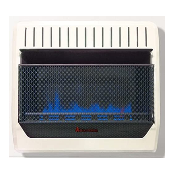
VENT - FREE GAS WALL
HEATER
OWNER'S OPERATION AND
INSTALLATION MANUAL
BLUE FLAME MODELS
BF30T - BB
WARNING: If the information in this manual is not
followed exactly, a fire or explosion may result causing
property damage, personal injury or loss of life.
— Do not store or use gasoline or other flammable va-
pors and liquids in the vicinity of this or any other
appliance.
— WHAT TO DO IF YOU SMELL GAS
• Do not try to light any appliance.
• Do not touch any electrical switch; do not use any
phone in your building.
• Immediately call your gas supplier from a neighbor's
phone. Follow the gas supplier's instructions.
• If you cannot reach your gas supplier, call the fire
department.
— Installation and service must be performed by a quali-
fied installer, service agency or the gas supplier.
WARNING: This appliance is equipped for natural and
propane gas. Field conversion is not permitted other than
between natural or propane gases.
Before returning to your retailer, call our customer service department at
Questions, problems, missing parts?
1-866-573-0674, 8:00 am - 4:30 pm CST, Monday through Friday
Advertisement
Chapters
Table of Contents

Related Manuals for Procom HearthSense BF30T-BB


Summary of Contents for Procom HearthSense BF30T-BB
- Page 1 VENT - FREE GAS WALL HEATER OWNER’S OPERATION AND INSTALLATION MANUAL BLUE FLAME MODELS BF30T - BB WARNING: If the information in this manual is not followed exactly, a fire or explosion may result causing property damage, personal injury or loss of life. —...
-
Page 2: Table Of Contents
TABLE OF CONTENTS Safety ............3 Operation ..........18 Qualified Installing Agency ......4 Electrical Connection ....... 20 Specifications ..........5 Electrical Wiring ........20 Product Features ........5 Inspecting Burners........21 Local Codes..........5 Care And Maintenance ......22 Preparing For Installation ...... -
Page 3: Safety
SAFETY IMPORTANT: Read this owner’s agent is added to the gas. The odor helps you manual carefully and completely detect a gas leak. However, the odor added to the gas can fade. Gas may be present even before trying to assemble, op- though no odor exists. -
Page 4: Qualified Installing Agency
SAFETY may create a white powder residue within WARNING: Do not place burner box or on adjacent walls or furniture. clothing or other flammable 8. Do not use heater if any part has been material on or near the appli- under water. -
Page 5: Specifications
SPECIFICATIONS Model BF30T-BB Ignition Piezo Ignitor Gas Type Natural Propane BTU/Hr Input Max. (available) 30,000 30,000 BTU/Hr Input Min. (available) 15,000 24,000 Pressure Regulator Setting 4" W.C. 9" W.C. Max. 9.5" Max. 14" Inlet Gas Pressure* (inches of water) Min. 5" Min. -
Page 6: Preparing For Installation
PREPARING FOR INSTALLATION Before beginning assembly or operation of Ignitor Button the product, make sure all parts are present. Compare parts with package contents list and Control Knob Figure 1. If any part is missing or damaged, do not attempt to assemble, install or operate the product. -
Page 7: Air For Combustion And Ventilation
AIR FOR COMBUSTION AND VENTILATION WARNING: This heater shall WARNING: This heater shall not be installed in a room or not be installed in a confined space space unless the required vol- or unusually tight construction unless provisions are provided ume of indoor combustion air is provided by the method de- for adequate combustion and... - Page 8 AIR FOR COMBUSTION AND VENTILATION VENTILATION AIR Ventilation Air From Inside Building Ventilation Air From Outdoors Provide extra fresh air by using ventilation This fresh air would come from an adjoining grills or ducts. You must provide two perma- unconfined space. When ventilating to an nent openings: one within 12"...
-
Page 9: Installation
INSTALLATION IMPORTANT: Vent-free heaters add moisture NOTICE: This heater is intended to the air. Although this is beneficial, installing for use as supplemental heat. Use heater in rooms without enough ventilation air this heater along with your primary may cause mildew to form too much moisture. heating system. - Page 10 INSTALLATION INSTALLING THERMOSTAT SENSING BULB ( OPTIONAL ) For Heaters with Blower Installed Only 1. Carefully remove bulb clips with ther- mostat sensing bulb from the shipping position in the back panel, see Figure 5. 2. Insert bulb clips into 2 rectangular slots Thermostat beside the shipping location (relocation Sensing...
- Page 11 INSTALLATION Marking Screw Locations Attaching to Wall Anchor Method 1. Tape mounting bracket to wall where For attaching mounting bracket to hollow heater will be located. Make sure mount- walls (wall areas between studs) or solid walls ing bracket is level. (concrete or masonry): 1.
- Page 12 INSTALLATION Placing Heater On Mounting Bracket 1. Locate two horizontal slots on back panel of heater (see Figure 10). 2. Place heater onto mounting bracket. Slide Front View horizontal slots onto stand-out tabs on mounting bracket. Front View Horizontal Slots Wall Heater Stand-...
- Page 13 INSTALLATION GAS SELECTION Yellow Natural Gas This appliance is factory Plunger Underneath Blue Propane preset for propane gas. No Metal Cap Gas Plunger changes are required for connecting to propane. Only a qualified installer or service technician can perform gas se- lection and connecting to gas supply.
- Page 14 INSTALLATION INSTALLATION: YELLOW Fitting supplied 1. Remove the metal cap installed over the by installer, NG regulator inlet. may vary. 2. Install metal cap over Propane regulator Metal Cap inlet. This will keep debris out of regulator. Use only the metal cap. DO NOT use an off the shelf 3/8"...
- Page 15 INSTALLATION CONNECTING TO GAS SUPPLY WARNING: A qualified ser- CAUTION: For propane gas, Never connect heater directly vice technician must connect to the gas supply. This heater heater to gas supply. Follow all requires an external regulator local codes. (not supplied). Install the external WARNING: This appliance regulator between the heater and requires a 3/8"...
- Page 16 INSTALLATION For propane installations, apply pipe joint external regulator with the vent pointing down sealant lightly to male threads. This will as shown in Figure 17. Pointing the vent down prevent excess sealant from going into pipe. protects it from freezing rain or sleet. Excess sealant in pipe could result in clogged Install sediment trap in supply line as shown heater valves.
- Page 17 INSTALLATION Test Pressures Equal To or Less Than 1/2 PSIG (3.5 kPa) 1. Close equipment shutoff valve (see Fig- Gas Valve ure 18). Propane 2. Pressurize supply piping system by either Supply Tank opening propane supply tank valve for propane gas or opening main gas valve located on or near gas meter for natural gas or using compressed air.
-
Page 18: Operation
OPERATION FOR YOUR SAFETY READ BEFORE LIGHTING • Immediately call your gas supplier WARNING: If you do not fol- from a neighbor’s phone. Follow the low these instructions exactly, a gas supplier’s instructions. fire or explosion may result caus- • If you cannot reach your gas supplier, call the fire department. - Page 19 OPERATION 7. Keep control knob pressed in for 30 sec- WARNING: If input gas onds after lighting pilot. After 30 seconds, type is NG, make sure NG pilot release control knob. If control knob does not pop up when released, contact a quali- burner ignites.
-
Page 20: Electrical Connection
ELECTRICAL CONNECTION FOR BLOWER KIT Do not use this heater if any part of it has been under water. Immediately call a qualified ser- Cover of vice technician to inspect the Grounded Grounding Pin heater and replace any part of Outlet Box the electrical system which has been under water. -
Page 21: Inspecting Burners
INSPECTING BURNERS IMPORTANT: Owner’s should check pilot flame pattern and burner flame pattern often. Incorrect flame patterns indicate the need for cleaning (see Care and Maintenance, page 22) or service. WARNING: Only a qualified service person should service and repair heater. This includes maintenance requiring replacement or alteration of components. -
Page 22: Care And Maintenance
CARE AND MAINTENANCE WARNING: Turn off heater and let cool before servicing. CAUTION: You must keep control areas, burner, and circulating air passageways of heater clean. Inspect these areas of heater before each use. Have heater inspected yearly by a qualified service techni- cian. -
Page 23: Troubleshooting
CARE AND MAINTENANCE MAINTENANCE OF BLOWER MOTOR ( IF EQUIPPED ) Always disconnect the appliance from the use, periodic cleaning must be done more main power supply and allow it to cool frequently. If the heater blows alternating cold before any servicing operation. and warm air, check the fan for free movement and for debris restricting air flow. - Page 24 TROUBLESHOOTING Only a qualified installer should bypass the pressure switch. Remove front panel of heater (see page 10). Locate the gas regulator. To by- pass the pressure switch locate the set screw on the regulator. Use a small flat bladed screw driver to turn the set screw counterclockwise 2 turns.
- Page 25 TROUBLESHOOTING Problem Possible Cause Corrective Action ODS/pilot lights but flame 1. Control knob is not fully 1. Press in control knob fully. goes out when control pressed in. knob is released. 2. Control knob is not pressed 2. After ODS/pilot lights, keep in long enough.
-
Page 26: Technical Service
Ventilation require- ments, page 7. TECHNICAL SERVICE You may have further questions about installation, operation, or troubleshooting. If so, contact ProCom Heating, Inc. at 1-866-573-0674 When calling, please have your model and serial numbers of your heater ready. HearthSense 200549-05A... -
Page 27: Replacement Parts
ACCESSORIES Purchase these heater accessories from your local dealer. If they can not supply these acces- sories, contact ProCom Heating, Inc. at 1-866-573-0674 for information. UNIVERSAL GAS APPLIANCE CONNECTION KIT Model HSVFIK - For all gas heater models. Includes general fittings needed to connect heater to gas line. - Page 28 PARTS MODEL BF30T - BB HearthSense 200549-05A...
- Page 29 PARTS MODEL BF30T - BB This list contains replaceable parts for your heater. When ordering replacement parts, follow the instructions listed under Replacement Parts on page 27 of this manual. ITEM PART # DESCRIPTION 161562-01 Mounting Bracket 161133-01 Piezo Ignitor 160960-01 Cap with Seal MGB100-RW...
- Page 30 NOTES ________________________________________________________________________ ________________________________________________________________________ ________________________________________________________________________ ________________________________________________________________________ ________________________________________________________________________ ________________________________________________________________________ ________________________________________________________________________ ________________________________________________________________________ ________________________________________________________________________ ________________________________________________________________________ ________________________________________________________________________ ________________________________________________________________________ ________________________________________________________________________ ________________________________________________________________________ ________________________________________________________________________ ________________________________________________________________________ ________________________________________________________________________ ________________________________________________________________________ ________________________________________________________________________ ________________________________________________________________________ ________________________________________________________________________ ________________________________________________________________________ ________________________________________________________________________ ________________________________________________________________________ ________________________________________________________________________ ________________________________________________________________________ ________________________________________________________________________ ________________________________________________________________________ ________________________________________________________________________ ________________________________________________________________________ ________________________________________________________________________ ________________________________________________________________________ ________________________________________________________________________ HearthSense 200549-05A...
- Page 31 NOTES ________________________________________________________________________ ________________________________________________________________________ ________________________________________________________________________ ________________________________________________________________________ ________________________________________________________________________ ________________________________________________________________________ ________________________________________________________________________ ________________________________________________________________________ ________________________________________________________________________ ________________________________________________________________________ ________________________________________________________________________ ________________________________________________________________________ ________________________________________________________________________ ________________________________________________________________________ ________________________________________________________________________ ________________________________________________________________________ ________________________________________________________________________ ________________________________________________________________________ ________________________________________________________________________ ________________________________________________________________________ ________________________________________________________________________ ________________________________________________________________________ ________________________________________________________________________ ________________________________________________________________________ ________________________________________________________________________ ________________________________________________________________________ ________________________________________________________________________ ________________________________________________________________________ ________________________________________________________________________ ________________________________________________________________________ ________________________________________________________________________ ________________________________________________________________________ ________________________________________________________________________ HearthSense 200549-05A...
-
Page 32: Warranty
We make no other warranty, expressed or implied. NEW PRODUCTS Standard Warranty: ProCom Heating, Inc. warrants this product to be free from defects in materials and components for ONE (1) year from the date of first purchase, provided that the product has been properly installed by a qualified installer in accordance with all local codes and instructions furnished with the unit, operated and maintained in accordance with all applicable instructions. - Page 33 CALENTADOR DE GAS DE PARED SIN VENTILAS MANUAL DE FUNCIONAMIENTO Y INSTALACIÓN DEL PROPIETARIO MODELOS LLAMA AZUL BF30T - BB ADVERTENCIA: si la información contenida en este manual no se sigue al pie de la letra, se puede producir un incendio o una explosión que podría ocasionar daños a la propiedad, lesiones personales o la pérdida de la vida.
- Page 34 TABLA DE CONTENIDOS Seguridad ..........35 Funcionamiento ........52 Especificaciones ........37 Conexión Eléctrica........54 Agencia de Instalación Calificada.... 37 Cableado Eléctrico ........55 Características del Producto ....37 Inspección del calentador ......56 Normas Locales........38 Cuidado y mantenimiento ......57 Desempaque ...........
-
Page 35: Seguridad
SEGURIDAD IMPORTANTE: Lea este manual del de la gripe, con dolores de cabeza, mareos y/o náusea. Si usted presenta estos síntomas, propietario cuidadosa y completa- es posible que el calentador no esté funcio- mente antes de intentar ensamblar, nando correctamente. ¡Respire aire fresco operar o dar servicio a este calen- inmediatamente! Haga que le den servicio tador. - Page 36 SEGURIDAD correctamente. Este calentador tiene un ADVERTENCIA: La pantalla sistema de apagado de seguridad con o protección contra incendios detección de agotamiento de oxígeno diseñada para este electrodo- (ODS). El ODS apaga el calentador cuan- méstico sin ventilación debe do no hay suficiente aire fresco. Consulte Aire para combustión y ventilación, en instalarse antes de la operación.
-
Page 37: Especificaciones
ESPECIFICACIONES MODELO BF30T-BB Encendido Piezoeléctrico Tipo de gas Natural Propano BTU/h de entrada máx. (disponible) 30,000 30,000 BTU/Hr de entrada mín. (disponible) 15,000 24,000 Ajuste del regulador de presión: 4" de c.a. 9" de c.a. Máx. 9.5" Máx. 14" Presión del gas de entrada* (pulg. -
Page 38: Características Del Producto
CARACTERÍSTICAS DEL PRODUCTO PILOTO DE SEGURIDAD 2 OPCIONES DE GAS DISPONIBLES El calentador posee un piloto que cuenta con un sistema de apagado de seguridad El calentador está diseñado para funcionar por medio de un sensor de agotamiento de con gas propano o con gas natural. El calenta- oxígeno (ODS). -
Page 39: Vapor De Agua: Un Producto Derivado De Los Calentadores De Habitación Sin Ventilación
PREPARACIÓN PARA LA INSTALACIÓN Antes de comenzar el montaje o funciona- Botón de encendido miento del producto, asegúrese de que todas las partes están presentes. Compare las Perilla de piezas con la lista de contenido del paquete control y la Figura 1. Si alguna parte falta o está da- ñada, no intente montar, instalar u operar el producto. -
Page 40: Aire Para Combustión Y Ventilación
AIRE PARA COMBUSTIÓN Y VENTILACIÓN ADVERTENCIA: Este calen- ADVERTENCIA: Este calen- tador no se debe instalar en un tador no se debe instalar en una espacio reducido o excepcional- habitación o espacio a menos mente hermético a menos que se que el volumen requerido de aire tomen las precauciones necesa- de combustión en interiores es... - Page 41 AIRE PARA COMBUSTIÓN Y VENTILACIÓN AIRE PARA VENTILACIÓN Aire del interior de la construcción Aire del exterior para ventilación para ventilación Proporcione aire fresco adicional mediante Este aire fresco viene de un espacio adyacente el uso de rejillas o conductos de ventilación. no confinado.
-
Page 42: Instalación
INSTALACIÓN AVISO: Este calentador está PRECAUCIÓN: Este calen- diseñado para utilizarse como tador crea corrientes de aire calefacción adicional. Use este caliente. Estas corrientes mue- calentador junto con su sistema ven el calor hacia la superficie de calefacción principal. No ins- de las paredes próximas al tale este calentador como fuente calentador. - Page 43 INSTALACIÓN UBICACIÓN DEL TECHO CALENTADOR Un mínimo Este calentador está diseñado para ser mon- de 91.5 cm tado en una pared. Para mayor comodidad y (36") 15.2 cm eficiencia, instale el calentador: (6") Distancias 1. Cuando hay un fácil acceso para la ope- mínimas ración, inspección y servicio.
- Page 44 INSTALACIÓN clips que se encuentran en el paquete de hardware. DESMONTAJE DEL PANEL ANTERIOR 1. Retire los 4 tornillos que fijan el panel frontal. Tornillo Panel anterior Figura 6 - Desmontaje del panel anterior 2. Con cuidado, deslice el panel frontal hacia delante. COLOCACIÓN DEL Asegúrese de que el soporte de montaje CALENTADOR EN LA PARED...
- Page 45 INSTALACIÓN 3. Quite la cinta y el soporte de montaje de la pared. Instalación del soporte de montaje a la pared Nota: Los anclajes de pared, los tornillos de montaje y los separadores se encuentran en Figura 8 - Cómo doblar el anclaje el paquete de ferretería.
- Page 46 INSTALACIÓN montaje. Deslice las ranuras horizontales Nota: No vuelva a colocar el panel anterior hacia las lengüetas salientes del soporte en este momento. Coloque el panel anterior después de hacer las conexiones de gas y de montaje. de revisar si hay fugas. Instalación de separadores de INSTALACIÓN DE PATAS DE pared...
- Page 47 INSTALACIÓN SELECCIÓN DE GAS Amarilla gas natural Este aparato viene ajustado émbolo debajo Émbolo de gas de fábrica para gas propano. enchufe del metal propano azul No se requieren cambios para la conexión a propano. Sólo un instalador o técnico de servicio calificado puede realizar la selección de gas y la conexión al suministro de gas.
- Page 48 INSTALACIÓN PARA GAS NATURAL ( NG ) Racor INSTALACIÓN: AMARILLO suministrados 1. Retire la tapa metálica instalada sobre la por el instalador, entrada del regulador NG. puede variar. Tapa de metal Instale la tapa de metal sobre entrada del regulador propano. Esto evitará que los residuos fuera del regulador.
- Page 49 INSTALACIÓN CONEXIÓN AL SUMINISTRO DE GAS ADVERTENCIA: Una per- PRECAUCIÓN: Para gas sona de servicio capacitada propano, nunca conecte el calen- debe conectar el calentador al tador directamente al suministro suministro de gas. Siga todas de gas propano. Este calentador las normas locales.
- Page 50 INSTALACIÓN Diámetros usuales de tubería de entrada El instalador debe proveer un regulador exter- Utilice tuberías de hierro negro de 3/8" o más no. El regulador externo reducirá la presión del grandes. La instalación debe incluir la válvula gas entrante. Debe reducir la presión del gas de cierre del equipo, la unión y el tapón con entrante de manera que esté...
- Page 51 INSTALACIÓN REVISIÓN DE LAS CONEXIONES DE GAS ADVERTENCIA: Después ADVERTENCIA: Nunca use una lla- de instalar el calentador o de ma al descubierto para verificar si hay darle servicio, pruebe todas las fugas. Aplique en todas las uniones conexiones y tubos de gas de la algún líquido de detección de fugas unidad, tanto internas como ex- que no sea corrosivo.
-
Page 52: Funcionamiento
INSTALACIÓN Comprobación de la presión de las conexiones de gas del calentador 1. Abra la válvula de cierre del equipo (con- Aplique en todas las uniones algún líquido sulte la figura 18, página 51). para detectar fugas que no sea corrosivo. La formación de burbujas indicará... - Page 53 FUNCIONAMIENTO INSTRUCCIONES DE ENCENDIDO 6. Continúe presionando la perilla de control 1. ¡ALTO! Lea la información de seguridad en la página 52. y, al mismo tiempo, oprima y suelte el botón de encendido. Esto encenderá el 2. Asegúrese de que la válvula de cierre del piloto.
-
Page 54: Conexión Eléctrica
FUNCIONAMIENTO ADVERTENCIA: Si el tipo de PRECAUCIÓN: no intente entrada de gas es NG, asegúrese ajustar los niveles de calefac- de que el quemador del piloto NG ción por medio de la válvula de encienda. Si el tipo de entrada de cierre del equipo. -
Page 55: Cableado Eléctrico
CONEXIÓN ELÉCTRICA INSTRUCCIONES DE CONEXIÓN A TIERRA Este calentador fue diseñado para su uso con 120 voltios. El cable tiene un enchufe, como se muestra en la Figura 23. Hay un adaptador Cubierta de disponible, como se muestra en la C, para Cover of la caja de conectar enchufes con conexión a tierra de... -
Page 56: Inspección Del Calentador
INSPECCIÓN DEL CALENTADOR IMPORTANTE: El propietario debe revisar frecuentemente los patrones de la llama del piloto y de la llama del quemador. Patrones de llama incorrectos indican la necesidad de limpieza o servicio de mantenimiento (consulte Cuidado y mantenimiento, página 57). ADVERTENCIA: Sólo una persona de servicio capacitada debe repararlo o darle servicio. -
Page 57: Cuidado Y Mantenimiento
CUIDADO Y MANTENIMIENTO ADVERTENCIA: Apague el calentador y deje que se enfríe antes de darle mantenimiento. PRECAUCIÓN: Debe mantener limpias las áreas de control, el quemador y las vias de circulación de aire del calentador. Inspec- cione estas áreas del calentador antes de cada uso. Haga que una persona de servicio calificada inspeccione el calentador una vez al año. - Page 58 CUIDADO Y MANTENIMIENTO ODS/PILOTO Utilice una aspiradora, aire comprimido o Electrodo del Quemador de encendedor un cepillo pequeño, de cerdas suaves para gas natural Termopar limpiarlos. Quemador de Si la llama del piloto tiene la punta amarilla, Gas Propano indica la presencia de polvo y suciedad en el ensamble del piloto.
-
Page 59: Solución De Problemas
SOLUCIÓN DE PROBLEMAS ADVERTENCIA: Si percibe olor a gas • Cierre el suministro de gas. • No intente encender ningún aparato. • No toque ningún interruptor eléctrico; no use ningún teléfono en el edificio. • Llame inmediatamente a su proveedor de gas desde el teléfono de algún vecino. - Page 60 SOLUCIÓN DE PROBLEMAS La tubería de suministro de gas completa, incluidas las conexiones en el interior del calentador debe probar contra fugas por el instalador autorizado. Después de la fuga probar el instalador calificado debe encender el aparato. Consulte el patrón correcto de la llama, como se ilustra en la página 56.
- Page 61 SOLUCIÓN DE PROBLEMAS Problema Causa Posible Acción correctiva El piloto/ODS se en- 1. La perilla de control no está 1. Presione la perilla de control ciende pero la llama se presionada completamente. completamente. extingue cuando la perilla 2. La perilla de control no se 2.
- Page 62 SOLUCIÓN DE PROBLEMAS Problema Causa Posible Acción correctiva Llamas amarillas alta 1. No hay suficiente aire. 1. Revise el quemador en busca durante la combustión de polvo y residuos. Si los hay, en el quemador. limpie el quemador (consulte Cuidado y mantenimiento, en la página 57).
-
Page 63: Consejos Para Servicio
Es posible que tenga preguntas adicionales sobre la instalación, el funcionamiento o la solución de problemas. De ser así, póngase en contacto con ProCom Heating, Inc. al 1-866-573-0674. Al llamar tenga a la mano los números de modelo y serie de su calentador. - Page 64 PIEZAS MODELO BF30T - BB HearthSense 200549-05A...
-
Page 65: Piezas De Repuesto
ACCESORIOS Adquiera estos accesorios con su distribuidor local. Si no pueden proporcionarle estos ac- cesorios, comuníquese ProCom Heating, Inc. al 1-866-573-0674 para obtener información. KIT DE CONEXIÓN DE APARATO DE GAS UNIVERSAL Modelo HSVFIK: para todos los modelos de calentadores de gas. Incluye accesorios gene- rales necesarios para conectar el calentador a la línea de gas. - Page 66 NOTES ________________________________________________________________________ ________________________________________________________________________ ________________________________________________________________________ ________________________________________________________________________ ________________________________________________________________________ ________________________________________________________________________ ________________________________________________________________________ ________________________________________________________________________ ________________________________________________________________________ ________________________________________________________________________ ________________________________________________________________________ ________________________________________________________________________ ________________________________________________________________________ ________________________________________________________________________ ________________________________________________________________________ ________________________________________________________________________ ________________________________________________________________________ ________________________________________________________________________ ________________________________________________________________________ ________________________________________________________________________ ________________________________________________________________________ ________________________________________________________________________ ________________________________________________________________________ ________________________________________________________________________ ________________________________________________________________________ ________________________________________________________________________ ________________________________________________________________________ ________________________________________________________________________ ________________________________________________________________________ ________________________________________________________________________ ________________________________________________________________________ ________________________________________________________________________ ________________________________________________________________________ HearthSense 200549-05A...
- Page 67 NOTES ________________________________________________________________________ ________________________________________________________________________ ________________________________________________________________________ ________________________________________________________________________ ________________________________________________________________________ ________________________________________________________________________ ________________________________________________________________________ ________________________________________________________________________ ________________________________________________________________________ ________________________________________________________________________ ________________________________________________________________________ ________________________________________________________________________ ________________________________________________________________________ ________________________________________________________________________ ________________________________________________________________________ ________________________________________________________________________ ________________________________________________________________________ ________________________________________________________________________ ________________________________________________________________________ ________________________________________________________________________ ________________________________________________________________________ ________________________________________________________________________ ________________________________________________________________________ ________________________________________________________________________ ________________________________________________________________________ ________________________________________________________________________ ________________________________________________________________________ ________________________________________________________________________ ________________________________________________________________________ ________________________________________________________________________ ________________________________________________________________________ ________________________________________________________________________ ________________________________________________________________________ HearthSense 200549-05A...
-
Page 68: Garantía
ProCom Heating, Inc. No se autorizará ninguna devolución. Se proporcionarán piezas para reparar el producto.
Need help?
Do you have a question about the HearthSense BF30T-BB and is the answer not in the manual?
Questions and answers
At a setting of 3 on the control what would be the approximate LP. Fuel burn per hour?