Download Print this page

Procom MN100TBA-B Owner's Operation And Installation Manual

Blue flame vent-free gas space heater

Advertisement

Quick Links

WARNING: If the information in this manual is not
followed exactly, a fire or explosion may result causing
property damage, personal injury or loss of life.
— Do not store or use gasoline or other flammable va-
pors and liquids in the vicinity of this or any other
appliance.
— WHAT TO DO IF YOU SMELL GAS
• Do not try to light any appliance.
• Do not touch any electrical switch; do not use any
phone in your building.
• Immediately call your gas supplier from a neighbor's
phone. Follow the gas supplier's instructions.
• If you cannot reach your gas supplier, call the fire
department.
— Installation and service must be performed by a quali-
fied installer, service agency or the gas supplier.
INSTALLER: Leave this manual with the appliance.
CONSUMER: Retain this manual for future reference.
Questions, problems, missing parts? Before returning to your retailer, call
our customer service department at 1-866-573-0674, 7:30 am - 4:30 pm CST,
Monday through Friday or email service@usaprocom.com
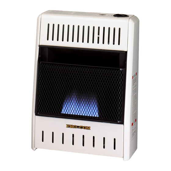
BLUE FLAME
VENT - FREE GAS SPACE
HEATER
OWNER'S OPERATION AND
INSTALLATION MANUAL
MODELS
MN100TBA - B AND ML100TBA - B
PFS
F09 - 022
CSA/ANS
Z21.11.2 2019
Unvented
Room Heaters
®
US

Advertisement

loading
Need help?

Need help?

Do you have a question about the MN100TBA-B and is the answer not in the manual?

Questions and answers

Summary of Contents for Procom MN100TBA-B

  • Page 1 BLUE FLAME VENT - FREE GAS SPACE HEATER OWNER’S OPERATION AND INSTALLATION MANUAL MODELS MN100TBA - B AND ML100TBA - B ® F09 - 022 CSA/ANS Z21.11.2 2019 Unvented Room Heaters WARNING: If the information in this manual is not followed exactly, a fire or explosion may result causing property damage, personal injury or loss of life.
  • Page 2: Table Of Contents

    TABLE OF CONTENTS Safety ............3 Operation ..........14 Specifications ..........4 Inspecting Heater ........17 Product Identification ......... 5 Care And Maintenance ......18 Qualified Installing Agency ......5 Troubleshooting ........19 Product Features ........5 Parts ............22 Air For Combustion and Ventilation ...
  • Page 3: Safety

    SAFETY NATURAL AND PROPANE GAS: Natural IMPORTANT: Read this owner’s and propane gas are odorless. An odor- manual carefully and completely making agent is added to the gas. The odor before trying to assemble, op- helps you detect a gas leak. However, the erate, or service this heater.
  • Page 4: Specifications

    If heater keeps shutting off, have it serviced. 6. Do not run heater: • Where flammable liquids or vapors are used or stored. • Under dusty conditions. SPECIFICATIONS MODEL MN100TBA-B ML100TBA-B Ignition Piezo Piezo Gas Type Natural Gas Propane Gas...
  • Page 5: Product Identification

    PRODUCT IDENTIFICATION Ignitor Button Control Knob Grill Burners Front Panel Heater Cabinet Figure 1 - Vent-Free Gas Heater QUALIFIED INSTALLING AGENCY Only a qualified agency should install and a) Installing, testing, or replacing gas piping replace gas piping, gas utilization equipment or accessories, and repair and equipment ser- b) Connecting, installing, testing, repairing, vicing.
  • Page 6: Air For Combustion And Ventilation

    LOCAL CODES Install and use heater with care. Follow all State of Massachusetts: The installation local codes. In the absence of local codes, must be made by a licensed plumber or use the latest edition of The National Fuel gas fitter in the Commonwealth of Mas- Gas Code, ANSI Z223.1/NFPA 54*.
  • Page 7 AIR FOR COMBUSTION AND VENTILATION Exhaust fans, fireplaces, clothes dryers and fuel burning appliances draw air from the house to operate. You must provide adequate fresh 12" air for these appliances. This will insure proper venting of vented fuel-burning appliances. Ventilation Grills WARNING: This heater shall Into Adjoining Room,...
  • Page 8: Installation

    INSTALLATION NOTICE: This heater is intended CAUTION: This heater cre- for use as supplemental heat. ates warm air currents. These Use this heater along with your currents move heat to wall sur- primary heating system. Do not faces next to heater. Installing install this heater as your pri- heater next to vinyl or cloth wall mary heat source.
  • Page 9: Fastening Heater To Wall

    INSTALLATION CEILING 36" Minimum 6" Minimum From Sides of Heater Right Side Left Side 2" Minimum to Top Surface of Carpeting, Tile or Other Combustible Material FLOOR Figure 4 - Mounting Clearances as Viewed From Front of Heater FASTENING HEATER TO WALL Mounting Bracket The mounting bracket is located on back panel of heater (see Figure 5).
  • Page 10 INSTALLATION Marking Screw Locations 1. Drill holes at marked locations using 1. Tape mounting bracket to wall where 5/16" drill bit. For solid walls (concrete or heater will be located. Make sure mount- masonry), drill at least 1" deep. ing bracket is level. 2.
  • Page 11 INSTALLATION Installing Bottom Mounting Bracket 9. Tighten both screws until heater is firmly 1. Install bottom bracket to heater bottom secured to wall. Do not over tighten. with two screws. It may be more conve- Note: Do not replace front panel at this time. nient to remove heater from wall bracket Replace front panel after making gas connec- to attach.
  • Page 12: Connecting To Gas Supply

    INSTALLATION CONNECTING TO GAS SUPPLY WARNING: A qualified ser- CAUTION: For propane gas, NEVER connect heater directly vice technician must connect to the gas supply. This heater heater to gas supply. Follow all requires an external regulator local codes. (not supplied). Install the external WARNING: This appliance regulator between the heater and gas supply.
  • Page 13: Checking Gas Connections

    INSTALLATION The installer must supply an external regula- Install sediment trap in supply line as shown tor. The external regulator will reduce incom- in Figure 12. Place sediment trap where it is ing gas pressure. You must reduce incoming within reach for cleaning. Place sediment trap gas pressure to between 11"...
  • Page 14 INSTALLATION 6. Reconnect heater and equipment shutoff 4. Check all joints of gas supply piping sys- valve to gas supply. Check reconnected tem. Apply a noncorrosive leak detection fittings for leaks. fluid to all joints. If bubbles form, there may be a leak.
  • Page 15: Operation

    OPERATION FOR YOUR SAFETY READ BEFORE LIGHTING not use any phone in your building. WARNING: If you do not fol- • Immediately call your gas supplier low these instructions exactly, a from a neighbor’s phone. Follow the fire or explosion may result caus- gas supplier’s instructions.
  • Page 16: Thermostat Control Operation

    OPERATION Ignitor Electrode Thermocouple CAUTION: Do not try to ad- Pilot Burner just heating levels by using the equipment shutoff valve. Figure 17 - Pilot THERMOSTAT CONTROL OPERATION The thermostatic control used on this model differs from standard thermostats. You set standard thermostats to a specific temperature such as 72°...
  • Page 17: Inspecting Heater

    INSPECTING HEATER IMPORTANT: Owner’s should check pilot flame pattern and burner flame pattern often. Incorrect flame patterns indicate the need for cleaning (see Care and Maintenance, page 18) or service. WARNING: Only a qualified service person should service and repair heater. This includes maintenance requiring replacement or alteration of components.
  • Page 18: Care And Maintenance

    CARE AND MAINTENANCE WARNING: Turn off heater and let cool before servicing. CAUTION: You must keep control areas, burner, and circulating air passageways of heater clean. Inspect these areas of heater before each use. Have heater inspected yearly by a qualified service techni- cian.
  • Page 19: Troubleshooting

    TROUBLESHOOTING WARNING: If you smell gas: • Shut off gas supply. • Do not try to light any appliance. • Do not touch any electrical switch; do not use any phone in your building. • Immediately call your gas supplier from a neighbor’s phone. Fol- low the gas supplier’s instructions.
  • Page 20 TROUBLESHOOTING Problem Possible Cause Corrective Action ODS/pilot lights but flame 1. Control knob is not fully 1. Press in control knob fully. goes out when control pressed in. knob is released. 2. Control knob is not pressed 2. After ODS/pilot lights, keep in long enough.
  • Page 21 TROUBLESHOOTING Problem Possible Cause Corrective Action Slight smoke or odor 1. Residues from manufactur- 1. Problem will stop after a few during initial operation. ing process. hours of operation. Heater produces a click- 1. Metal is expanding while 1. This is common with most ing/ticking noise just after heating or contracting while heaters.
  • Page 22: Parts

    PARTS MODEL MN100 ( H,T ) BA - B (not field replaceable) This list contains replaceable parts for your heater. When ordering replacement parts, follow the instructions listed under Replacement Parts on page 30 of this manual. ITEM PART # DESCRIPTION ML008-03-RW Lower Front Panel...
  • Page 23: Replacement Parts

    • Type of gas used (Propane or Natural gas/ • The replacement part number ACCESSORIES Purchase these heater accessories from your local dealer. If they can not supply these ac- cessories, contact ProCom Heating, Inc. at 1-866-573-0674 or email service@usaprocom. for information. EQUIPMENT SHUTOFF VALVE For all models.
  • Page 24: Warranty

    We make no other warranty, expressed or implied. NEW PRODUCTS Standard Warranty: ProCom Heating, Inc. warrants this product to be free from defects in materials and components for ONE (1) year from the date of first purchase, provided that the product has been properly installed by a qualified installer in accordance with all local codes and instructions furnished with the unit, operated and maintained in accordance with all applicable instructions.

This manual is also suitable for:

Ml100tba-b