Table of Contents
Advertisement
Available languages
Available languages
Quick Links
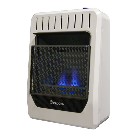
VENT-FREE GAS WALL
HEATER
OWNER'S OPERATION AND
INSTALLATION MANUAL
BLUE FLAME MODEL
MG10HBF
WARNING: If the information in this manual is not
followed exactly, a fire or explosion may result causing
property damage, personal injury or loss of life.
— Do not store or use gasoline or other flammable va-
pors and liquids in the vicinity of this or any other
appliance.
— WHAT TO DO IF YOU SMELL GAS
• Do not try to light any appliance.
• Do not touch any electrical switch; do not use any
phone in your building.
• Immediately call your gas supplier from a neighbor's
phone. Follow the gas supplier's instructions.
• If you cannot reach your gas supplier, call the fire
department.
— Installation and service must be performed by a quali-
fied installer, service agency or the gas supplier.
WARNING: This appliance is equipped for Natural and
Propane gas. Field conversion is not permitted other than
between natural or propane gases.
Questions, problems, missing parts? Before returning to your retailer, call
our customer service department at 1-866-573-0674, 7:30 am - 4:15 pm CST,
Monday through Friday or email customerservice@usaprocom.com
Advertisement
Chapters
Table of Contents

Related Manuals for Procom MG10HBF


Summary of Contents for Procom MG10HBF
- Page 1 HEATER OWNER’S OPERATION AND INSTALLATION MANUAL BLUE FLAME MODEL MG10HBF WARNING: If the information in this manual is not followed exactly, a fire or explosion may result causing property damage, personal injury or loss of life. — Do not store or use gasoline or other flammable va- pors and liquids in the vicinity of this or any other appliance.
-
Page 2: Table Of Contents
TABLE OF CONTENTS Safety ............3 Operation ..........18 Specifications ..........4 Inspecting Burners........20 Qualified Installing Agency ......5 Care And Maintenance ......21 Product Features ........5 Troubleshooting ........22 Local Codes..........5 Technical Service........25 Preparing For Installation ......6 Parts ............ -
Page 3: Safety
SAFETY NATURAL AND PROPANE/LP GAS: Natural IMPORTANT: Read this owner’s and Propane/LP gas are odorless. An odor- manual carefully and completely making agent is added to the gas. The odor before trying to assemble, op- helps you detect a gas leak. However, the erate, or service this heater. -
Page 4: Specifications
6. Do not run heater: • Where flammable liquids or vapors are used or stored. • Under dusty conditions. SPECIFICATIONS Model MG10HBF Ignition Piezo Ignitor Gas Type Natural Propane BTU/Hr Input Max. (available) 10,000 10,000 BTU/Hr Input Min. -
Page 5: Qualified Installing Agency
QUALIFIED INSTALLING AGENCY Only a qualified agency should install and a) Installing, testing, or replacing gas piping replace gas piping, gas utilization equipment or accessories, and repair and equipment ser- b) Connecting, installing, testing, repairing, vicing. The term “qualified agency” means any or servicing equipment;... -
Page 6: Preparing For Installation
PREPARING FOR INSTALLATION Before beginning assembly or operation of Ignitor Button the product, make sure all parts are present. Control Compare parts with package contents list and Knob Figure 1. If any part is missing or damaged, do not attempt to assemble, install or operate the product. -
Page 7: Air For Combustion And Ventilation
AIR FOR COMBUSTION AND VENTILATION WARNING: This heater shall WARNING: This heater shall not be installed in a room or not be installed in a confined space space unless the required vol- or unusually tight construction ume of indoor combustion air unless provisions are provided for adequate combustion and is provided by the method de-... - Page 8 AIR FOR COMBUSTION AND VENTILATION VENTILATION AIR Ventilation Air From Inside Building Ventilation Air From Outdoors Provide extra fresh air by using ventilation This fresh air would come from an adjoining grills or ducts. You must provide two perma- unconfined space. When ventilating to an nent openings: one within 12"...
-
Page 9: Installation
INSTALLATION NOTICE: This heater is intended CAUTION: This heater cre- for use as supplemental heat. ates warm air currents. These Use this heater along with your currents move heat to wall sur- primary heating system. Do not faces next to heater. Installing install this heater as your pri- heater next to vinyl or cloth wall mary heat source. - Page 10 INSTALLATION LOCATING HEATER This heater is designed to be mounted on a wall. For convenience and efficiency, install heater: 1. Where there is easy access for operation, inspection, and service. 2. In the coldest part of room. When installing the appliance directly on carpeting, tile or other combustible material other than wood flooring, the appliance shall be installed on a metal or wood panel extended the full width and depth of the appliance.
- Page 11 INSTALLATION Marking Screw Locations 3. Insert mounting screws through bracket 1. Tape mounting bracket to wall where and into wall studs. heater will be located. Make sure mount- 4. Tighten screws until mounting bracket is ing bracket is level. firmly fastened to wall studs. Attaching to Wall Anchor Method WARNING: Maintain mini- For attaching mounting bracket to hollow...
- Page 12 INSTALLATION Placing Heater On Mounting 6. Place spacers between bottom mounting Bracket holes and wall anchor or drilled hole. 1. Locate two horizontal slots on back panel 7. Hold spacer in place with one hand. With other of heater (see Figure 9). hand, insert mounting screw though bottom 2.
- Page 13 INSTALLATION GAS SELECTION This appliance is factory INLET GAS PRESSURE preset for propane/LP gas. MAX 1/2 PSIG (3.5 KPA) No changes are required for connecting to propane/LP. Only a qualified installer or service technician can perform gas selec- tion and connecting to gas supply. Gas Connection CAUTION: Two gas line in- Figure 11 - Bottom of Heater...
- Page 14 INSTALLATION 2. Apply thread sealant to the threads on a Use only the cap supplied on the 3/8" NPT brass connection fitting. While regulator. Do not use an off the pushing in, rotate the fitting clockwise until shelf pipe plug. This can damage the threads engage the regulator.
- Page 15 INSTALLATION CONNECTING TO GAS SUPPLY WARNING: A qualified ser- CAUTION: For propane/LP vice technician must connect gas, Never connect heater directly to the gas supply. This heater heater to gas supply. Follow all requires an external regulator local codes. (not supplied). Install the external WARNING: This appliance regulator between the heater and requires a 3/8"...
- Page 16 INSTALLATION Apply pipe joint sealant lightly to male threads. as shown in Figure 14. Pointing the vent down This will prevent excess sealant from going protects it from freezing rain or sleet. into pipe. Excess sealant in pipe could result Install sediment trap in supply line as shown in clogged heater valves.
- Page 17 INSTALLATION Test Pressures Equal To or Less Than 1/2 PSIG (3.5 kPa) Gas Valve 1. Close equipment shutoff valve (see Fig- ure 15). Propane/LP 2. Pressurize supply piping system by either Supply Tank using compressed air or opening gas sup- ply valve.
-
Page 18: Operation
OPERATION FOR YOUR SAFETY READ BEFORE LIGHTING • Immediately call your gas supplier WARNING: If you do not fol- from a neighbor’s phone. Follow the low these instructions exactly, a gas supplier’s instructions. fire or explosion may result caus- • If you cannot reach your gas supplier, call the fire department. - Page 19 OPERATION 7. Keep control knob pressed in for 30 CAUTION: Do not try to ad- seconds after lighting pilot. After 30 just heating levels by using the seconds, release control knob. If control knob does not pop up when released, equipment shutoff valve.
-
Page 20: Inspecting Burners
INSPECTING BURNERS IMPORTANT: Owner’s should check pilot flame pattern and burner flame pattern often. Incorrect flame patterns indicate the need for cleaning (see Care and Maintenance, page 21) or service. WARNING: Only a qualified service person should service and repair heater. This includes maintenance requiring replacement or alteration of components. -
Page 21: Care And Maintenance
CARE AND MAINTENANCE WARNING: Turn off heater and let cool before servicing. CAUTION: You must keep control areas, burner, and circulating air passageways of heater clean. Inspect these areas of heater before each use. Have heater inspected yearly by a qualified service techni- cian. -
Page 22: Troubleshooting
TROUBLESHOOTING WARNING: If you smell gas: • Shut off gas supply. • Do not try to light any appliance. • Do not touch any electrical switch; do not use any phone in your building. • Immediately call your gas supplier from a neighbor’s phone. Fol- low the gas supplier’s instructions. - Page 23 TROUBLESHOOTING Problem Possible Cause Corrective Action When ignitor button is 1. Ignitor electrode is posi- 1. Replace electrode. pressed in, there is no tioned wrong. Ignitor elec- spark at ODS/pilot. trode is broken. 2. Ignitor electrode is not con- 2. Replace ignitor cable. nected to ignitor cable.
- Page 24 TROUBLESHOOTING Problem Possible Cause Corrective Action ODS/pilot lights but flame 1. Control knob is not fully 1. Press in control knob fully. goes out when control pressed in. knob is released. 2. Control knob is not pressed 2. After ODS/pilot lights, keep in long enough.
-
Page 25: Technical Service
Ventilation require- ments, page 7. TECHNICAL SERVICE You may have further questions about installation, operation, or troubleshooting. If so, contact ProCom Heating, Inc. at 1-866-573-0674. When calling, please have your model and serial numbers of your heater ready. www.usaprocom.com 200310-01B... -
Page 26: Parts
PARTS MODEL MG10HBF www.usaprocom.com 200310-01B... - Page 27 PARTS MODEL MG10HBF This list contains replaceable parts for your heater. When ordering replacement parts, follow the instructions listed under Replacement Parts on page 28 of this manual. ITEM MG10HBF DESCRIPTION Back Body Panel 161132-01 Mounting Bracket 161133-01 Piezo Ignitor...
-
Page 28: Replacement Parts
REPLACEMENT PARTS Note: Use only original replacement parts. This will protect your warranty coverage for parts replaced under warranty. PARTS UNDER WARRANTY Contact authorized dealers of this product. • Model and serial number of your heater If they can’t supply original replacement •... -
Page 29: Accessories
ACCESSORIES Purchase these heater accessories from your local dealer. If they can not supply these acces- sories, contact ProCom Heating, Inc. at 1-866-573-0674 for information. EQUIPMENT SHUTOFF VALVE For all models. Equipment shutoff valve with 1/8" NPT tap. SERVICE HINTS When Gas Pressure Is Too Low •... -
Page 30: Warranty
We make no other warranty, expressed or implied. LIMITED WARRANTY ProCom Heating, Inc. warrants this product to be free from defects in materials and components for ONE (1) year from the date of first purchase, provided that the product has been properly installed by a qualified installer in accordance with all local codes and instructions furnished with the unit, operated and main- tained in accordance with all applicable instructions. - Page 31 MANUAL DE FUNCIONAMIENTO Y INSTALACIÓN DEL PROPIETARIO MODELO LLAMA AZUL MG10HBF ADVERTENCIA: si la información contenida en este manual no se sigue al pie de la letra, se puede producir un incendio o una explosión que podría ocasionar daños a la propiedad, lesiones personales o la pérdida de la vida.
- Page 32 TABLA DE CONTENIDOS Seguridad ..........35 Instalación ..........42 Especificaciones ........37 Funcionamiento ........52 Agencia de Instalación Calificada.... 37 Inspección del calentador ......55 Características del Producto ....37 Cuidado y mantenimiento ......56 Normas Locales........38 Solución de problemas ......58 Desempaque ...........
-
Page 33: Seguridad
SEGURIDAD de la gripe, con dolores de cabeza, mareos IMPORTANTE: Lea este manual del y/o náusea. Si usted presenta estos síntomas, propietario cuidadosa y completa- es posible que el calentador no esté funcio- mente antes de intentar ensamblar, nando correctamente. ¡Respire aire fresco operar o dar servicio a este calen- inmediatamente! Haga que le den servicio al calentador. - Page 34 SEGURIDAD 4. Mantenga todas las entradas de aire del ADVERTENCIA: Este calen- frente y fondo del calentador limpias y tador alcanza temperaturas muy libres de escombros. Esto asegurará aire altas cuando el calentador está suficiente para la combustión.. en funcionamiento. Mantenga a 5.
-
Page 35: Especificaciones
ESPECIFICACIONES MODELO MG10HBF Encendido Piezoeléctrico Tipo de gas Natural Propano BTU/h de entrada máx. (disponible) 10,000 10,000 BTU/Hr de entrada mín. (disponible) 5,000 8,000 Ajuste del regulador de presión: 4" de c.a. 9" de c.a. Máx. 9.5" Máx. 14" Presión del gas de entrada* (pulg. de agua) Mín. -
Page 36: Normas Locales
NORMAS LOCALES Instale y use el calentador con cuidado. Siga Estado de Massachusetts: La instalación todas las normas locales. A falta de normas loca- la debe realizar un plomero o un instalador les, utilice la última edición del Código Nacional de gas con licencia para ejercer en el es- de Gas Combustible, ANSI Z223.1/NFPA 54*. -
Page 37: Preparación Para La Instalación
PREPARACIÓN PARA LA INSTALACIÓN Botón de encendido Antes de comenzar el montaje o funciona- miento del producto, asegúrese de que todas Perilla de las partes están presentes. Compare las control piezas con la lista de contenido del paquete y la Figura 1. Si alguna parte falta o está da- ñada, no intente montar, instalar u operar el producto. -
Page 38: Aire Para Combustión Y Ventilación
AIRE PARA COMBUSTIÓN Y VENTILACIÓN ADVERTENCIA: Este calen- ADVERTENCIA: Este calen- tador no se debe instalar en un tador no se debe instalar en una espacio reducido o excepcional- habitación o espacio a menos mente hermético a menos que se que el volumen requerido de aire tomen las precauciones necesa- de combustión en interiores es... - Page 39 AIRE PARA COMBUSTIÓN Y VENTILACIÓN AIRE PARA VENTILACIÓN Aire del interior de la construcción Aire del exterior para ventilación para ventilación Proporcione aire fresco adicional mediante Este aire fresco viene de un espacio adyacente el uso de rejillas o conductos de ventilación. no confinado.
-
Page 40: Instalación
INSTALACIÓN AVISO: Este calentador está PRECAUCIÓN: Este calen- diseñado para utilizarse como tador crea corrientes de aire calefacción adicional. Use este caliente. Estas corrientes mue- calentador junto con su sistema ven el calor hacia la superficie de calefacción principal. No ins- de las paredes próximas al tale este calentador como fuente calentador. - Page 41 INSTALACIÓN UBICACIÓN DEL CALENTADOR TECHO Este calentador está diseñado para ser mon- Un mínimo tado en una pared. Para mayor comodidad y de 91.5 cm eficiencia, instale el calentador: (36") 15.2 cm (6") 1. Cuando hay un fácil acceso para la ope- Distancias ración, inspección y servicio.
- Page 42 INSTALACIÓN COLOCACIÓN DEL CALENTADOR EN LA PARED 2. Marque la ubicación de los tornillos en la Soporte de montaje pared (consulte la figura 6). El soporte de montaje se encuentra en el panel posterior del calentador. Se colocó con Nota: Marque únicamente el último orificio cinta en ese lugar para el transporte.
- Page 43 INSTALACIÓN Método de fijación a anclajes de pared Colocación del calentador en el soporte de montaje Para fijar el soporte de montaje en paredes huecas (el área entre las vigas) o en paredes 1. Localice las dos ranuras horizontales en sólidas (de concreto o mampostería) el panel posterior del calentador (consulte la figura 9).
- Page 44 INSTALACIÓN Instalación de separadores de pared 1. Coloque el calentador sobre el soporte de montaje de pared. 2. Marque la ubicación de los tornillos en la pared. 3. Quite el calentador del soporte de montaje. Front View 4. Si va a instalar los tornillos de montaje inferiores Front View Vista frontal en una pared hueca o sólida, instale los ancla-...
- Page 45 INSTALACIÓN SELECCIÓN DE GAS Este aparato viene ajustado INLET GAS PRESSURE MAX 1/2 PSIG (3.5 KPA) de fábrica para gas propano/ LP. No se requieren cambios para la conexión a propano/ Conexión de gas LP. Sólo un instalador o técnico de servicio calificado puede Figura 11 - Parte inferior del calentador realizar la selección de gas y la...
- Page 46 INSTALACIÓN 2. Aplique sellador de roscas a las roscas en el Utilice solamente el tapón suminis- accesorio de conexión. Mientras presiona, gire trado en el regulador. No utilice un hacia la derecha el ajuste hasta que las roscas fuera el tapón del tubo estante. Esto se acoplan al regulador.
- Page 47 INSTALACIÓN CONEXIÓN AL SUMINISTRO DE GAS ADVERTENCIA: Una per- PRECAUCIÓN: Para gas pro- sona de servicio capacitada pano/LP, nunca conecte el calenta- debe conectar el calentador al dor directamente al suministro de suministro de gas. Siga todas gas propano/LP. Este calentador las normas locales.
- Page 48 INSTALACIÓN Diámetros usuales de tubería de entrada El instalador debe proveer un regulador exter- Utilice tuberías de hierro negro de 3/8" o más no. El regulador externo reducirá la presión del grandes. La instalación debe incluir la válvula gas entrante. Debe reducir la presión del gas de cierre del equipo, la unión y el tapón con entrante de manera que esté...
- Page 49 INSTALACIÓN REVISIÓN DE LAS CONEXIONES DE GAS ADVERTENCIA: Después ADVERTENCIA: Nunca use una de instalar el calentador o de llama al descubierto para verificar darle servicio, pruebe todas las si hay fugas. Aplique líquido no conexiones y tubos de gas de la corrosivo para detectar fugas en unidad, tanto internas como ex- todas las uniones.
-
Page 50: Funcionamiento
INSTALACIÓN Comprobación de la presión de las conexiones de gas del calentador 1. Abra la válvula de cierre del equipo (con- (consulte la figura 16 o 17, página 51). sulte la figura 15, página 51). Aplique en todas las uniones algún líquido para detectar fugas que no sea corrosivo. - Page 51 FUNCIONAMIENTO INSTRUCCIONES DE ENCENDIDO • Si al soltar la perilla de control ésta no 1. ¡ALTO! Lea la información de seguridad en la página 52. regresa a su posición original, llame a un técnico de servicio calificado o a su 2.
- Page 52 FUNCIONAMIENTO Electrodo del Quemador de PRECAUCIÓN: no intente encendedor gas natural Termopar ajustar los niveles de calefac- Quemador de ción por medio de la válvula de Gas Propano/LP cierre del equipo. ADVERTENCIA: Si el tipo de entrada de gas es NG, asegúrese Orificio de entrada de de que el quemador del piloto NG...
-
Page 53: Inspección Del Calentador
INSPECCIÓN DEL CALENTADOR IMPORTANTE: El propietario debe revisar frecuentemente los patrones de la llama del piloto y de la llama del quemador. Patrones de llama incorrectos indican la necesidad de limpieza o servicio de mantenimiento (consulte Cuidado y mantenimiento, página 56). ADVERTENCIA: Sólo una persona de servicio capacitada debe repararlo o darle servicio. -
Page 54: Cuidado Y Mantenimiento
CUIDADO Y MANTENIMIENTO ADVERTENCIA: Apague el calentador y deje que se enfríe antes de darle mantenimiento. PRECAUCIÓN: Debe mantener limpias las áreas de control, el quemador y las vias de circulación de aire del calentador. Inspec- cione estas áreas del calentador antes de cada uso. Haga que una persona de servicio calificada inspeccione el calentador una vez al año. - Page 55 CUIDADO Y MANTENIMIENTO ODS/PILOTO Utilice una aspiradora, aire comprimido o Electrodo del Quemador de encendedor un cepillo pequeño, de cerdas suaves para gas natural Termopar limpiarlos. Quemador de Si la llama del piloto tiene la punta amarilla, Gas Propano/LP indica la presencia de polvo y suciedad en el ensamble del piloto.
-
Page 56: Solución De Problemas
SOLUCIÓN DE PROBLEMAS ADVERTENCIA: Si percibe olor a gas • Cierre el suministro de gas. • No intente encender ningún aparato. • No toque ningún interruptor eléctrico; no use ningún teléfono en el edificio. • Llame inmediatamente a su proveedor de gas desde el teléfono de algún vecino. - Page 57 SOLUCIÓN DE PROBLEMAS Problema Causa Posible Acción correctiva Cuando se presiona el 1. Electrodo de encendido 1. Remplace el electrodo del botón del encendedor, no está mal colocado. Electro- encendedor. hay chispa en el piloto/ do de encendido está roto. ODS.
- Page 58 SOLUCIÓN DE PROBLEMAS Problema Causa Posible Acción correctiva El piloto/ODS se en- 1. La perilla de control no está 1. Presione la perilla de control ciende pero la llama se presionada completamente. completamente. extingue cuando la perilla 2. La perilla de control no se 2.
- Page 59 SOLUCIÓN DE PROBLEMAS Problema Causa Posible Acción correctiva Llamas amarillas alta 1. No hay suficiente aire. 1. Revise el quemador en busca durante la combustión de polvo y residuos. Si los hay, en el quemador. limpie el quemador (consulte Cuidado y mantenimiento, en la página 59).
-
Page 60: Consejos Para Servicio
SOLUCIÓN DE PROBLEMAS Problema Causa Posible Acción correctiva El calentador produce 1. En el calentador se están 1. Abra la ventana para ventilar olores no deseados. quemado vapores prove- la habitación. Deje de utilizar nientes de pintura, fijador los productos que ocasionan para el cabello, pegamen- el olor mientras el calentador tos, productos de limpieza,... -
Page 61: Piezas De Repuesto
Es posible que tenga preguntas adicionales sobre la instalación, el funcionamiento o la solución de problemas. De ser así, póngase en contacto con ProCom Heating, Inc. al 1-866-573-0674. Al llamar tenga a la mano los números de modelo y serie de su calentador. - Page 62 PIEZAS MODELO MG10HBF www.usaprocom.com 200310-01B...
- Page 63 PIEZAS MODELO MG10HBF Esta lista contiene las piezas remplazables utilizadas en el calentador. Al hacer un pedido de piezas, siga las instrucciones listadas en Piezas de repuesto en la página 63 de este manual. Art. MG10HBF Descripción Cant. Parte trasera del cuerpo...
-
Page 64: Garantía
No hacemos ninguna otra garantía, expresa o implícita. GARANTÍA LIMITADA ProCom Heating, Inc. garantiza que este producto está libre de defectos en materiales y componentes por un 1 año desde la fecha de la primera compra, siempre que el producto ha sido correctamente instalado por personal calificado de conformidad con todos los códigos locales e instrucciones de la unidad, opera-...
Need help?
Do you have a question about the MG10HBF and is the answer not in the manual?
Questions and answers