
Related Manuals for Endress+Hauser AT1000 AT1


Summary of Contents for Endress+Hauser AT1000 AT1
- Page 1 Operating Instructions Analog Transmitter AT1000 AT1 Alarm Transmitter for Mechanical Level Gauges BA00414G/08/EN/03.13 71240706...
-
Page 2: Table Of Contents
Disposal ........23 Contact Addresses of Endress+Hauser ....23 Installation. -
Page 3: Safety Instructions
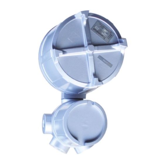
Analog Transmitter AT1000 AT1 1 Safety Instructions Safety Instructions Designated Use AT1 analog transmitter is designed to be installed onto LT and LTC series level gauging systems. The device transmits the level information into electric current, voltage, and resistance signals. It can also be equipped with a maximum of six alarm contact signals. -
Page 4: Notes On Safety Conventions And Symbols
Analog Transmitter AT1000 AT1 1 Safety Instructions Notes on Safety Conventions and Symbols To highlight safety-relevant or alternative operating procedures in this manual, the following conventions have been used, each indicated by a corresponding symbol on the left. Safety Conventions... -
Page 5: Identification
Analog Transmitter AT1000 AT1 2 Identification Identification Device Designation 2.1.1 Nameplate The follow technical data are given on the instrument nameplate: Order cord Serial number Measuring range Explosion model Protection class Power Analog Output Analog output Contact output Contact output... -
Page 6: Ordering Information
Analog Transmitter AT1000 AT1 2 Identification Ordering Information Output: 4 - 20mA 10 - 50mA 0 - 1mA 0 - 20mA 0 - 10mVDC 0 - 1VDC Special version, TSP-no. to be spec. Power Type: Alarm Output: Not used 2 - point... - Page 7 Analog Transmitter AT1000 AT1 2 Identification Measuring Range: A 1.5m 1 2.5m C 3m D 3.5m E 4m 2 5m F 6m G 8m 3 10m H 12m J 14m 4 16m 5 20m K 25m 6 30m 9 Special version, TSP-no. to be spec.
-
Page 8: Scope Of Delivery
Analog Transmitter AT1000 AT1 2 Identification Scope of Delivery Caution! It is extremely important to follow the instructions concerning the unpacking, transportation and storage of measuring instruments provided in the chapter "Incoming Acceptance, Transportation, Storage". The scope of delivery consists of: •... -
Page 9: Installation
Analog Transmitter AT1000 AT1 3 Installation Installation Incoming Acceptance, Transport, Storage 3.1.1 Incoming Acceptance Check the packing and contents for any signs of damage. Check the shipment, and make sure that nothing is missing and that the items match your order. - Page 10 Analog Transmitter AT1000 AT1 3 Installation Weather Proof Alarm Output: 0, 2 Points, Cable Entry G 3/4, NPT 3/4 Main body Cover Terminal Box Figure 3: Dimension of Weather Proof 1 Alarm Output: 0, 2, 4, 6 Points Main Body...
-
Page 11: Installation And Setting Transmitter
Analog Transmitter AT1000 AT1 3 Installation Installation and Setting of Transmitter Attach the stud bolt, nut, washer, and coupling to the level gauge to the level gauge and AT1 transmitter as shown in the diagram below. Preparation of Installation Remove the blind plate of the transmitter that is attached to back of the level gauge. - Page 12 Analog Transmitter AT1000 AT1 3 Installation Installation Procedure of Non Equipped Model of Alarm Contact Remove the cover of the transmitter if the transmitter is non-equipped alarm specification. Rotate the coupling to adjust the set level of the potentiometer (or the alarm) to correspond to the set level of the level gauge, and then close the main body cover.
- Page 13 Analog Transmitter AT1000 AT1 3 Installation Installation at Low Pressure (LT11/12/31/32) Stud Bolt Washer Rear of Float Level Gauge Hexagonal Nut Tooth look washer Hexagonal Nut Drive Shaft Coupling Pin Coupling Sprocket Wheel O-ring Figure 8: Installation for Low Pressure...
- Page 14 Analog Transmitter AT1000 AT1 3 Installation 3.3.1 Installation of Transmitter to Float Tank Gauge Transmitter Terminal box Level Gauge Sideways Flexible Fitting with M-type (both ends) Rnion Refer to cable entry for transmitter. Universal Fitting Thick Steel Figure 10: Transmitter and Tank Gauge...
-
Page 15: Wiring
Analog Transmitter AT1000 AT1 4 Wiring Wiring To maintain the transmitter and its accuracy, it is important to set the wiring and connection of the circuit to be within the accepted range. In AT1 analogue transmitter, there are several output signals. Be alert for the impedance that is caused by the circuit resistance as a result of electric output. - Page 16 Analog Transmitter AT1000 AT1 4 Wiring 5. With Alarm Contacts In case of with contacts in 1, 2, 3, and 4, the following circuits are provided. A Contact (Normal Open) Terminal No. Figure 15: A Contact B Contact (Normal Close) Terminal No.
-
Page 17: Operation
Analog Transmitter AT1000 AT1 5 Operation Operation Span Adjustment The zero point cannot be changed, however the location of the 100% level can easily be changed. When the level can be changed; Remove the main body cover when the tank level reaches to the desired 100% level. -
Page 18: Maintenance
Repairs The Endress+Hauser repair policy is based on the fact that the measuring devices have a modular design and that customers are able to undertake repairs themselves. Spare parts are contained in corresponding kits along with their related replacement instructions. Endress+Hauser provides spare parts for repairs of AT1000 or AT1, which are located with their order numbers on later pages (refer to "7.1 Spare Parts"). -
Page 19: Troubleshooting
7 Troubleshooting Troubleshooting Spare Parts Spare parts are contained in kits. Spare parts for AT1000 or AT1 which can be ordered from Endress+Hauser are shown with their order numbers in the diagram below. Contact Endress+Hauser service representatives for further assistance. - Page 20 Analog Transmitter AT1000 AT1 7 Troubleshooting Specification Specification 11 O-ring, packing 33 Electronic potentiometer 017880-5025 O ring, Main body, NBR 017871-1202 Potentiometer,CPP45,LT,LTC2230/2240 017880-5026 O ring, Terminal box , small, NBR 56004470 Potentiometer,CPP45,?LTC2110 017880-5027 O ring, El-compartment, large 35 Terminal 017871-1231...
- Page 21 Analog Transmitter AT1000 AT1 7 Troubleshooting 40 Gear Train Panel XPN0002 Gear Pannel Assembly Alarm Output: Not used 2 - point 4 - point 6 - point Installation Gauge: LT1100/LT1200/LT3100/LT3200 R:300 low pressure LT version LT1400/LT1600/LT3400/LT3600 R:300 high pressure LT version...
-
Page 22: Troubleshooting
In case of disposal, separate the various components according to their materials. Contact Addresses of Endress+Hauser The addresses of Endress+Hauser are given on the back cover of this operating manual. If you have any questions, do not hesitate to contact Endress+Hauser representative. -
Page 23: Technical Data
Analog Transmitter AT1000 AT1 8 Technical Data Technical Data 4 - 20mA, 10 - 50mA, 0 - 1mA, 0 - 20mA, 0 - 10mV, 0 - 1V Output Accuracy Analog Output 4 - 20mA, 10 - 50mA Output: Within ±0.5% 0 - 20mA, 0 - 10mV, 0 - 1V Output: Within ±0.7%... - Page 24 Declaration of Hazardous Material and De-Contamination Erklärung zur Kontamination und Reinigung Please reference the Return Authorization Number (RA#), obtained from Endress+Hauser, on all paperwork and mark the RA# RA No. clearly on the outside of the box. If this procedure is not followed, it may result in the refusal of the package at our facility.
- Page 25 Endress + Hauser Japan Co., Ltd. Product Center Yamanashi 862-1 Mitsukunugi Sakaigawa-cho Fuefuki-shi Yamanashi, 406-0846 Japan Phone: ++81 55 266 4964 Fax: ++81 55 266 4969 BA00414G/08/EN/03.13 71240706 FM+XML/DITA 11.0...
Need help?
Do you have a question about the AT1000 AT1 and is the answer not in the manual?
Questions and answers