Endress+Hauser iTEMP TMT82 Operating Instructions Manual
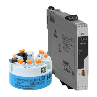
Dual-input temperature transmitter
Hide thumbs
Also See for iTEMP TMT82:
- Operating instructions manual (124 pages) ,
- Safety instructions (28 pages) ,
- Brief operating instructions (28 pages)

Related Manuals for Endress+Hauser iTEMP TMT82


Summary of Contents for Endress+Hauser iTEMP TMT82
-
Page 1: Operating Instructions
Products Solutions Services BA01028T/09/EN/17.17 71355027 Valid as of version 01.01 (device version) Operating Instructions iTEMP TMT82 Dual-input temperature transmitter... -
Page 3: Table Of Contents
TMT82 Table of contents Table of contents Important document information ..4 Maintenance ..... . 33 Function of document and how to use . -
Page 4: Important Document Information
Important document information iTEMP TMT82 Important document information Function of document and how to use 1.1.1 Document function These Operating Instructions contain all the information that is required in various phases of the life cycle of the device: from product identification, incoming acceptance and storage, to mounting, connection, operation and commissioning through to troubleshooting, maintenance and disposal. - Page 5 TMT82 Important document information Symbol Meaning Ground connection A grounded terminal which, as far as the operator is concerned, is grounded via a grounding system. A0011200 Protective ground connection A terminal which must be connected to ground prior to establishing any other connections.
-
Page 6: Tool Symbols
KA01095T/09/en The Brief Operating Instructions contain all the essential information from incoming acceptance to initial commissioning. The document types listed are available: In the Download Area of the Endress+Hauser Internet site: www.endress.com → Download Registered trademarks HART® Registered trademark of the HART® FieldComm Group... -
Page 7: Basic Safety Instructions
TMT82 Basic safety instructions Basic safety instructions Requirements for the personnel The personnel for installation, commissioning, diagnostics and maintenance must fulfill the following requirements: ‣ Trained, qualified specialists must have a relevant qualification for this specific function and task ‣... -
Page 8: Identification
Identification iTEMP TMT82 Identification Device designation The following options are available for identification of the device: • Nameplate specifications • Enter the serial number from the nameplate in the W@M Device Viewer (www.endress.com/deviceviewer): All data relating to the device and an overview of the Technical Documentation supplied with the device are displayed. -
Page 9: Scope Of Delivery
TMT82 Identification ® iTEMP TMT82 Made in Germany 2012 D-87484 Nesselwang Order code: TMT82-xxx/xx Ext. ord. cd.: XXXXXXXXXXX Ser. no.: XXXXXXXXX Input: 12-42 V Current cunsum.: 23,0 mA EH 08.001X II3G Ex nA II T6/T5/T4 Ta= -40 ...+ 55/70/85°C II3G Ex nL IIC T6/T5/T4 Ta= -40 ... - Page 10 Identification iTEMP TMT82 3.3.3 Functional safety The two device versions (head transmitter/DIN rail device) are optionally available for use in safety systems as per IEC 61508. • SIL 2: Hardware version • SIL 3: Software version Endress+Hauser...
-
Page 11: Installation
TMT82 Installation Installation Incoming acceptance, transport, storage 4.1.1 Incoming acceptance • Is the packaging or content damaged? • Is the delivery complete? Compare the scope of delivery against the information on your order form. 4.1.2 Transport and storage • Pack the device in such a way as to protect it reliably against impact for storage (and transportation). - Page 12 Installation iTEMP TMT82 4.3.1 Mounting the head transmitter Item A Item B . 7 2 i n ) Item C . 7 2 i n ) A0014269-EN 3 Head transmitter mounting (three versions) Item A Mounting in a terminal head (terminal head flat face as per DIN 43729)
- Page 13 TMT82 Installation Item B Mounting in a field housing Field housing cover Mounting screws with springs Head transmitter Field housing . 5 1 i n ) 6.5 mm . 8 3 i n ) (0.25 in) . 7 2...
- Page 14 Installation iTEMP TMT82 Mounting typical of North America A0008520 5 Head transmitter mounting Thermowell Insert Adapter, coupling Terminal head Head transmitter Mounting screws Thermometer design with thermocouples or RTD sensors and head transmitter: 1. Fit the thermowell (1) on the process pipe or the container wall. Secure the thermowell according to the instructions before the process pressure is applied.
- Page 15 After mounting, securely tighten the terminal head cover. The display can be used only with the appropriate terminal heads - cover with viewing window (e.g. TA30 from Endress+Hauser). 4.3.2 Mounting the DIN rail transmitter...
-
Page 16: Post-Installation Check
Installation iTEMP TMT82 A0017821 7 Mounting the DIN rail transmitter 1. Slide the upper DIN rail clip upwards and the lower clip downwards until they click into place. 2. Fit the device on the DIN rail from the front. -
Page 17: Wiring
TMT82 Wiring Wiring CAUTION ‣ Switch off power supply before installing or connecting the device. Failure to observe this may result in destruction of parts of the electronics. ‣ When installing Ex-approved devices in a hazardous area please take special note of the instructions and connection schematics in the respective Ex documentation added to these Operating Instructions. -
Page 18: Connecting The Sensor Cables
Wiring iTEMP TMT82 Terminal assignment of DIN rail transmitter Supply voltage 4...20 mA 1/+ 2/- Test Sensor input 1 Test Sensor input 2 RTD, Ω 4-, 3- and 2-wire RTD, Ω 3- and 2-wire TMT82 (black) (black) TC, mV TC, mV ®... -
Page 19: Connecting The Power Supply And Signal Cables
TMT82 Wiring 5.2.1 Connecting to spring terminals A flat-bladed screwdriver, size 3 mm is required. A0008322 10 Spring terminal connection Pos. A, solid wire: 1. Strip wire end. Min. stripping length 10 mm (0.39 in). 2. Insert the wire end into the terminal (A). -
Page 20: Shielding And Grounding
Wiring iTEMP TMT82 Please also observe the general procedure on → 17. 2- 1+ 2- 1+ A0017841 11 Connecting the signal cables and power supply Head transmitter installed in field housing Head transmitter installed in terminal head DIN rail transmitter mounted on DIN rail Terminals for HART ®... -
Page 21: Post-Connection Check
TMT82 Wiring Post-connection check Device condition and specifications Notes Is the device or cable undamaged (visual check)? Electrical connection Notes Does the supply voltage match the specifications on • Head transmitter: U = 11 to 42 V the nameplate? •... -
Page 22: Operating Options
Operating options iTEMP TMT82 Operating options Overview of operation options ADDR WRITE LOCK DISPL. 180° A0014460 13 Operating options of the temperature transmitter PLC (programmable logic control) Transmitter power supply unit, e.g. RN221N (with communication resistor) ® Connection for HART... -
Page 23: Structure And Function Of The Operating Menu
TMT82 Operating options Structure and function of the operating menu 6.2.1 Structure of the operating menu Operating menu for operators and maintenances Setup Device tag Unit Sensor type Lower range value Upper range value Advanced setup Enter access code... - Page 24 Operating options iTEMP TMT82 Configuration in the SIL mode differs from the standard mode and ist described in the Functional Safety Manual. For more information please refer to the Functional Safety Manual SD01172T/09. Submenus and user roles Certain parts of the menu are assigned to certain user roles. Each user role corresponds to typical tasks within the lifecycle of the device.
-
Page 25: Measured Value Display And Operating Elements
TMT82 Operating options Measured value display and operating elements 6.3.1 Display elements Head transmitter A0008549 14 Optional LC display for head transmitter Item No. Function Description Displays the TAG TAG, 32 characters long. ' C ommunication' symbol The communication symbol appears when read and write-accessing via the fieldbus protocol. - Page 26 Operating options iTEMP TMT82 Two LEDs on the front indicate the device status in accordance with NAMUR NE44. Type Function and characteristic Status LED (red) When the device is operating without errors, the device status is displayed. This function can no longer be guaranteed in the event of an error.
-
Page 27: Access To The Operating Menu Via The Operating Tool
FieldCare Function scope FDT/DTM-based plant asset management tool from Endress+Hauser. It can configure all smart field units in a system and help you manage them. By using the status information, it is also a simple but effective way of checking their status and condition. Access takes place via the HART ®... - Page 28 Operating options iTEMP TMT82 User interface A0014485-EN 6.4.2 Field Xpert Function scope Field Xpert is an industrial PDA with integrated touchscreen for commissioning and maintaining field devices in explosion hazardous and safe areas. It allows efficient configuration of FOUNDATION fieldbus, HART and WirelessHART devices via Bluetooth and/or Wifi interfaces.
- Page 29 TMT82 Operating options 6.4.5 SIMATIC PDM Function scope SIMATIC PDM is a standardized, manufacturer-independent program from Siemens for the operation, configuration, maintenance and diagnosis of intelligent field devices via the HART ® protocol. Source for device description files See data → 30 6.4.6...
-
Page 30: Integrating The Transmitter Via The Hart Protocol
Operating tools Operating tool Sources for obtaining device descriptions (DD) FieldCare • www.endress.com → Download Area • CD–ROM (contact Endress+Hauser) • DVD (contact Endress+Hauser) AMS Device Manager www.endress.com → Download Area (Emerson Process Management) SIMATIC PDM www.endress.com →... -
Page 31: Device Variables And Measured Values
TMT82 ® Integrating the transmitter via the HART protocol Device variable Measured value Tertiary device variable (TV) Sensor 1 Quaternary device variable (QV) Sensor 1 It is possible to change the assignment of device variables to process variables in the Expert →... - Page 32 TMT82 ® Integrating the transmitter via the HART protocol Command No. Designation 2, Cmd002 Read loop current and percent of range 3, Cmd003 Read dynamic variables and loop current 6, Cmd006 Write polling address 7, Cmd007 Read loop configuration...
-
Page 33: Commissioning
TMT82 Commissioning Commissioning Post-installation check Before commissioning the measuring point make sure that all final checks have been carried out: • Checklist “Post-installation check”, → 16 • Checklist “Post-connection check”, Switching on the transmitter Once the final checks have been successfully completed, it is time to switch on the supply voltage. -
Page 34: Accessories
Various accessories, which can be ordered with the device or subsequently from Endress +Hauser, are available for the device. Detailed information on the order code in question is available from your local Endress+Hauser sales center or on the product page of the Endress+Hauser website: www.endress.com. -
Page 35: Service-Specific Accessories
• Ideal measuring point design and sizing to suit the processes and needs of a wide range of industries The Konfigurator is available: On request from your Endress+Hauser sales office on a CD-ROM for local PC installation. Life cycle management for your plant... - Page 36 Accessories iTEMP TMT82 Accessories Description RN221N Active barrier with power supply for safe separation of 4 to 20 mA standard signal circuits. Has bidirectional HART ® transmission and optional HART ® diagnosis if transmitters are connected with monitoring of 4 to 20 mA signal or HART ®...
-
Page 37: Diagnostics And Troubleshooting
TMT82 Diagnostics and troubleshooting Diagnostics and troubleshooting 11.1 Troubleshooting Always start troubleshooting with the checklists below if faults occur after start up or during operation. This takes you directly (via various queries) to the cause of the problem and the appropriate remedial measures. - Page 38 Diagnostics and troubleshooting iTEMP TMT82 Application errors without status messages for RTD sensor connection Problem Possible cause Remedy Incorrect sensor orientation. Install the sensor correctly. Heat conducted by sensor. Observe the face-to-face length of the sensor. Device programming is incorrect Change the Connection type device (number of wires).
-
Page 39: Diagnostics Events
TMT82 Diagnostics and troubleshooting 11.2 Diagnostics events 11.2.1 Displaying diagnostics events A0014837 Display in the event of a warning Display in the event of an alarm Status signal in the header The display alternates between the primary measured value and the status - indicated by the appropriate letter (M, C or S) - plus the defined error number. - Page 40 Diagnostics and troubleshooting iTEMP TMT82 Diagnostics event and event text The fault can be identified by means of the diagnostics event. The event text helps you by providing information about the fault. Diagnostics event Status signal Event number Event text ↓...
- Page 41 TMT82 Diagnostics and troubleshooting Status signal Diagnostic from the Diagnostic behavior factory Short text Corrective measure number from the Can be factory changed Sensor connection 1. Check electrical connection of sensor. Alarm 2. Replace sensor. 3. Check sensor configuration.
-
Page 42: Spare Parts
Diagnostics and troubleshooting iTEMP TMT82 Status signal Diagnostic from the Diagnostic behavior factory Short text Corrective measure number from the Can be factory changed Linearization 1. Check configuration of sensor Alarm parameters. 2. Check configuration of special sensor linearizion. 3. Contact service. -
Page 43: Return
The measuring device must be returned if it is need of repair or a factory calibration, or if the wrong measuring device has been delivered or ordered. Legal specifications require Endress+Hauser, as an ISO-certified company, to follow certain procedures when handling products that are in contact with the medium. -
Page 44: Technical Data
Technical data iTEMP TMT82 Technical data For secure HART ® communication in accordance with functional safety as defined in IEC 61508 (SIL mode), measured values are sent securely from the transmitter via the ® HART protocol to a connected control system where they are processed further in a secure manner. - Page 45 TMT82 Technical data Thermocouples as Description Measuring range limits Min. span per standard Recommended temperature range: Type A (W5Re-W20Re) (30) 0 to +2 500 °C (+32 to +4 532 °F) 0 to +2 500 °C (+32 to +4 532 °F) 50 K (90 °F)
- Page 46 Technical data iTEMP TMT82 Failure information is created if the measuring information is missing or not valid. A complete list of all the errors occurring in the measuring system is created. Underranging Linear drop from 4.0 to 3.8 mA Overranging Linear increase from 20.0 to 20.5 mA...
-
Page 47: Power Supply
TMT82 Technical data 12.3 Power supply Supply voltage Values for non-hazardous areas, protected against polarity reversal: • Head transmitter – 11 V ≤ Vcc ≤ 42 V (standard) – 11 V ≤ Vcc ≤ 32 V (SIL mode) – I: ≤ 23 mA •... - Page 48 Technical data iTEMP TMT82 Reference operating • Calibration temperature: +25 °C ±3 K (77 °F ±5.4 °F) conditions • Supply voltage: 24 V DC • 4-wire circuit for resistance adjustment Maximum measured error In accordance with DIN EN 60770 and the reference conditions specified above. The measured error data correspond to 2 s (Gaussian distribution).
- Page 49 TMT82 Technical data Standard Description Measuring range Measured error (±) OIML R84: 2003, GOST 0.1 °C (0.18 °F) + 0.004% x Cu50 (14) –50 to +200 °C (–58 to +392 °F) ≤0.11 °C (0.2 °F) 6651-94 (MV - LRV) Resistance Resistance Ω...
- Page 50 Technical data iTEMP TMT82 Total measured error of transmitter at current output = √(Measured error digital² + Measured error D/A²) Sample calculation with Pt100, measuring range 0 to +200 °C (+32 to +392 °F), ambient temperature +25 °C (+77 °F), supply voltage 24 V: Measured error digital = 0.06 °C + 0.006% x (200 °C - (-200 °C)):...
- Page 51 TMT82 Technical data • Callendar-Van-Dusen coefficients (Pt100 resistance thermometer) The Callendar-Van-Dusen equation is described as: R T = R 0 [1+AT+BT²+C(T-100)T³] The coefficients A, B and C are used to match the sensor (platinum) and transmitter in order to improve the accuracy of the measuring system. The coefficients for a standard sensor are specified in IEC 751.
- Page 52 Technical data iTEMP TMT82 Ambient temperature: Supply voltage: Description Standard Influence (±) per 1 °C (1.8 °F) change Influence (±) per V change Ni100 (6) DIN 43760 ≤ 0.005 °C ≤ 0.005 °C IPTS-68 (0.009 °F) (0.009 °F) Ni120 (7) Cu50 (10) ≤...
- Page 53 TMT82 Technical data Ambient temperature: Supply voltage: Description Standard Influence (±) per 1 °C (1.8 °F) change Influence (±) per V change GOST ≤ 0.01 °C ≤ 0.01 °C Type L (43) R8.8585-2001 (0.02 °F) (0.02 °F) Voltage transmitter (mV) 0.001 %...
- Page 54 Technical data iTEMP TMT82 Long-term drift, thermocouples (TC) and voltage transmitters Description Standard Long-term drift (±) after 1 year after 3 years after 5 years Based on measured value ≤ 0.17 °C (0.306 °F) + 0.021% x ≤ 0.27 °C (0.486 °F) + 0.03% x ≤...
- Page 55 TMT82 Technical data Climate class • Head transmitter: climate class C1 as per EN 60654-1 • DIN rail device: climate class B2 as per EN 60654-1 Humidity • Condensation as per IEC 60 068-2-33: – Head transmitter permitted – DIN rail transmitter not permitted •...
- Page 56 Technical data iTEMP TMT82 12.6 Mechanical construction Design, dimensions Dimensions in mm (in) Head transmitter 5 (0.2) A0007301 16 Version with screw terminals Spring travel L ≥ 5 mm (not for US - M4 securing screws) Mounting elements for attachable measured value display TID10...
- Page 57 TMT82 Technical data Field housing All field housings have an internal shape and size in accordance with DIN EN 50446, flat face. Cable glands in the diagrams: M20x1.5 TA30A Specification • Two cable entries 107.5 (4.23) • Temperature: –50 to +150 °C (–58 to +302 °F) without cable gland •...
- Page 58 Technical data iTEMP TMT82 TA30H with display window in cover Specification • Flameproof (XP) version, explosion-protected, captive 125 (4.92) screw cap, with two cable entries • Temperature: –50 to +150 °C (–58 to +302 °F) for rubber seal without cable gland (observe max. permitted temperature of cable gland!) •...
- Page 59 Maritime guidelines For the type approval certificates (GL, BV etc.) currently available, please contact your Endress+Hauser Sales Center for information. All data relating to shipbuilding can be found in separate type approval certificates which can be requested as needed. UL approval UL recognized component (see www.ul.com/database, search for Keyword "E225237")
-
Page 60: Operating Menu And Parameter
Operating menu and parameter description iTEMP TMT82 Operating menu and parameter description The following tables list all the parameters in the "Setup", "Diagnostics" and "Expert" operating menus. The page reference indicates where a description of the parameter can be found in the manual. - Page 61 TMT82 Operating menu and parameter description Setup → Extended Setup→ Current output → Output current → 75 Measuring mode → 75 Out of range category → 76 Failure mode → 76 Failure current → 76 Current trimming 4 mA →...
- Page 62 Operating menu and parameter description iTEMP TMT82 Diagnosis → Device information → Device tag → 66 Serial number → 89 Firmware version → 89 Device name → 89 Order code → 89 Configuration counter → 90 Diagnosis →...
- Page 63 TMT82 Operating menu and parameter description Expert → Sensor → Sensor n → Sensor type n → 66 Connection type n → 67 2-wire compensation n → 67 Reference junction n → 67 RJ preset value →...
-
Page 64: Remedy Information
Operating menu and parameter description iTEMP TMT82 Current trimming 4 mA → 77 Current trimming 20 mA → 77 Expert → Communication → HART configuration → Device tag → 101 HART short tag → 101 HART address →... - Page 65 TMT82 Operating menu and parameter description Expert → Diagnosis → Diagnostic list→ Actual diagnostics count → 87 Actual diagnostics → 86 Actual diag channel → 87 Expert → Diagnosis → Event logbook → Previous diagnostics n →...
-
Page 66: Setup" Menu
Operating menu and parameter description iTEMP TMT82 13.1 "Setup" menu This menu contains all the parameters that are needed to configure the basic settings of the device. The transmitter can be put into operation with this limited parameter set. n = Stands for the number of sensor inputs (1 and 2) - Page 67 TMT82 Operating menu and parameter description Description Use this function to select the sensor type for the sensor input in question. • Sensor type 1: settings for sensor input 1 • Sensor type 2: settings for sensor input 2 Please observe the terminal assignment when connecting→...
- Page 68 Operating menu and parameter description iTEMP TMT82 Prerequisite A thermocouple (TC) sensor must be selected as the sensor type. Description Use this function to select reference junction measurement for temperature compensation of thermocouples (TC). • If Preset value is selected, the compensation value is specified via the RJ preset value parameter.
- Page 69 TMT82 Operating menu and parameter description Options • Sensor 1 (measured value) • Sensor 2 (measured value) • Device temperature • Average of the two measured values: 0.5 x (SV1+SV2) • Difference between sensor 1 and sensor 2: SV1-SV2 •...
- Page 70 Operating menu and parameter description iTEMP TMT82 13.1.1 "Extended Setup" submenu Corrosion monitoring Sensor connection cable corrosion can lead to false measured value readings. Therefore the unit offers the possibility of recognizing any corrosion before a measured value is affected. Corrosion monitoring is only possible for RTDs with a 4-wire connection and thermocouples.
- Page 71 TMT82 Operating menu and parameter description Navigation Setup → Advanced setup → Enter access code Expert → Enter access code Description Use this function to enable the service parameters via the operating tool. If an incorrect access code is entered, the user retains his current access authorization.
- Page 72 Operating menu and parameter description iTEMP TMT82 Navigation Setup → Advanced setup → Locking status Expert → Locking status Description Use this function to view the device locking status. The DIP switch for hardware locking is fitted on the display module. When write protection is activated, write access to the parameters is disabled.
- Page 73 TMT82 Operating menu and parameter description Description Use this function to select the category (status signal) which is displayed when corrosion is detected in the sensor connection cables. Only possible for RTD sensors with 4-wire connection and thermocouples (TC).
- Page 74 Operating menu and parameter description iTEMP TMT82 Drift/difference alarm delay Navigation Setup → Advanced setup → Sensor → Drift/difference alarm delay Expert → Sensor → Diagnostic settings → Drift/difference alarm delay Prerequisite The Drift/difference mode parameter must be activated with the Out band (drift) or In band option.
-
Page 75: Output Current
TMT82 Operating menu and parameter description "Current output" submenu Adjustment of the analog output (4 and 20 mA current trimming) Current trimming is used to compensate the analog output (D/A conversion). Here, the output current of the transmitter must be adapted so that it suits the value expected at the higher-order system. -
Page 76: Out Of Range Category
Operating menu and parameter description iTEMP TMT82 Additional information • Standard The output current increases with increasing temperatures • inverted The output current decreases with increasing temperatures Options • Standard • inverted Factory setting Standard Out of range category Navigation Setup →... -
Page 77: Current Trimming 4 Ma
TMT82 Operating menu and parameter description Description Use this function to set the value the current output adopts in an alarm condition. User entry 21.5 to 23.0 mA Factory setting 22.5 Current trimming 4 mA Navigation Setup → Advanced setup → Current output→ Current trimming 4 mA Expert →... -
Page 78: Format Display
Operating menu and parameter description iTEMP TMT82 Description Use this function to set the length of time the measured values are displayed if the values alternate on the display. The display only alternates between values if more than one measured value is defined. -
Page 79: Decimal Places 1
TMT82 Operating menu and parameter description Navigation Setup → Advanced setup → Display → Value 1 display Expert → System → Display → Value 1 display Description Use this function to select one of the measured values to be shown on the local display. -
Page 80: Value 3 Display
Operating menu and parameter description iTEMP TMT82 Options: • Off • Process value • Sensor 1 • Sensor 2 • Output current • Percent of range • Device temperature Factory settings Decimal places 2 Navigation Setup → Advanced setup → Display → Decimal places 2 Expert →... -
Page 81: Decimal Places 3
TMT82 Operating menu and parameter description Factory settings Decimal places 3 Navigation Setup → Advanced setup → Display → Decimal places 3 Expert → System → Display → Decimal places 3 Prerequisite A measured value is specified in the Value 3 display parameter. -
Page 82: Enter Sil Checksum
Operating menu and parameter description iTEMP TMT82 Navigation Setup → Advanced setup → SIL → Operational state Description Displays the device operational state in the SIL mode. Display • Checking SIL option • Startup normal mode • Wait for checksum •... -
Page 83: Timestamp Sil Configuration
TMT82 Operating menu and parameter description Description Use this function to display the SIL checksum entered. The SIL checksum displayed can be used to check the device configuration. If 2 devices have identical configurations, the SIL checksum is also identical. This can make for easy device replacement because if the checksum is the same, the device configuration is guaranteed to be identical too. -
Page 84: Force Safe State
Operating menu and parameter description iTEMP TMT82 Force safe state Navigation Setup → Advanced setup → SIL → Force safe state Prerequisite The Operational state parameter displays SIL mode active. Description During SIL proof testing this parameter is used to test error detection and the safe state of the device. - Page 85 TMT82 Operating menu and parameter description Description Sets a write protection code for the device. If the code is programmed into the device firmware it is saved in the device and the operating tool displays the value 0 so that the defined write protection code is not openly displayed for viewing.
-
Page 86: Diagnostics" Menu
Operating menu and parameter description iTEMP TMT82 13.2 "Diagnostics" menu All the information that describes the device, the device status and the process conditions can be found in this group. Actual diagnostics 1 Navigation Diagnostics → Actual diagnostics Expert → Diagnostics → Actual diagnostics 1 Description Use this function to display the current diagnostics message. - Page 87 TMT82 Operating menu and parameter description Display Hours (h) 13.2.1 "Diagnose list" submenu Up to 3 diagnostic messages currently pending are displayed in this submenu. If more than 3 messages are pending, the messages with the highest priority are shown on the display.
- Page 88 Operating menu and parameter description iTEMP TMT82 13.2.2 "Event logbook" submenu Previous diagnostics n n = Number of diagnostics messages (n = 1 to 5) Navigation Diagnostics → Diagnostics list → Previous diagnostics n Expert → Diagnostics → Diagnostics list → Previous diagnostics n Description Use this function to display the diagnostics messages that occurred in the past.
- Page 89 Use this function to display the serial number of the device. It can also be found on the nameplate. Uses of the serial number • To identify the measuring device quickly, e.g. when contacting Endress+Hauser. • To obtain specific information on the measuring device using the Device Viewer: www.endress.com/deviceviewer Display Max.
- Page 90 Operating menu and parameter description iTEMP TMT82 Configuration counter Navigation Diagnostics → Device info. → Configuration counter Expert → Diagnostics → Device info. → Configuration counter Description Use this function to display the counter reading for changes to device parameters.
- Page 91 TMT82 Operating menu and parameter description Sensor n max value n = Stands for the number of sensor inputs (1 and 2) Navigation Diagnostics → Measured values → Min/max values → Sensor n max value Expert → Diagnostics → Measured values → Min/max values → Sensor n max. value...
- Page 92 Operating menu and parameter description iTEMP TMT82 Reset device temp. min/max values Navigation Diagnostics → Measured values → Min/max values → Reset device temp. min/max values Expert → Diagnostics → Measured values → Min/max values → Reset device temp. min/max values...
- Page 93 TMT82 Operating menu and parameter description User entry 3.59 to 23.0 mA Factory setting 3.59 mA Endress+Hauser...
-
Page 94: Expert" Menu
Operating menu and parameter description iTEMP TMT82 13.3 "Expert" menu The parameter groups for the Expert setup contain all the parameters of the "Setup" and "Diagnostics" operating menus, as well as other parameters that are solely reserved for experts. Descriptions of the additional parameters can be found in this section. - Page 95 TMT82 Operating menu and parameter description Device temperature alarm → 72 Navigation Expert → System → Device temperature alarm "Display" submenu → 77 "Administration" submenu → 84 13.3.2 "Sensor" submenu "Sensor 1/2" submenu n = Stands for the number of sensor inputs (1 and 2)
- Page 96 Operating menu and parameter description iTEMP TMT82 "Sensor trimming" submenu Sensor error adjustment (sensor trimming) Sensor trimming is used to adapt the actual sensor signal to the linearization of the selected sensor type stored in the transmitter. Compared to sensor transmitter matching, sensor trimming only takes place at the start and end value and does not achieve the same level of accuracy.
- Page 97 TMT82 Operating menu and parameter description Prerequisite The Customer-specific option is enabled in the Sensor trimming parameter→ 96 . Description Lower point for linear characteristic calibration (this affects offset and slope). User entry Depends on the selected sensor type and the assignment of the current output (PV).
- Page 98 Operating menu and parameter description iTEMP TMT82 7. Enter the four coefficients A, B, C and R0. ß 8. If special linearization is also used for a second sensor, repeat steps 2 to 6. ß 9. End Sensor n lower limit Navigation Expert →...
- Page 99 TMT82 Operating menu and parameter description Call./v. Dusen coeff. A, B and C Navigation Expert → Sensor → Sensor n → Linearization → Call./v. Dusen coeff. A, B, C Prerequisite The RTD platinum (Callendar/Van Duse) option is enabled in the Sensor type parameter.
- Page 100 Operating menu and parameter description iTEMP TMT82 Navigation Expert → Sensor → Diagnostic settings → Calibration counter start Description Option to control the calibration counter. • The countdown duration (in days) is specified with the Calibration counter start value parameter.
- Page 101 TMT82 Operating menu and parameter description 13.3.3 "Output" submenu Measuring mode Navigation Expert → Output → Measuring mode Description Enables the inversion of the output signal. Additional information • Standard The output current increases with increasing temperatures • inverted...
- Page 102 Operating menu and parameter description iTEMP TMT82 User entry 0 ... 63 Factory setting Additional information The measured value can only be transmitted via the current value is the address is set to "0". The current is fixed at 4.0 mA for all other addresses (Multidrop mode).
- Page 103 TMT82 Operating menu and parameter description Factory setting 0xcc Device revision Navigation Expert → Communication → HART info → Device revision Description Use this function to view the device revision with which the device is registered with the HART ®...
- Page 104 Operating menu and parameter description iTEMP TMT82 HART message Navigation Expert → Communication → HART info → HART message Description Use this function to define a HART message which is sent via the HART protocol when requested by the master.
- Page 105 TMT82 Operating menu and parameter description Description Use this function to assign a measured variable to the primary HART value (PV). Options • Sensor 1 (measured value) • Sensor 2 (measured value) • Device temperature • Average of the two measured values: 0.5 x (SV1+SV2) •...
- Page 106 Operating menu and parameter description iTEMP TMT82 Assign TV Navigation Expert → Communication → HART output → Assign TV Description Use this function to assign a measured variable to the tertiary HART value (TV). Options See Assign current output (PV) parameter, → 104...
- Page 107 TMT82 Operating menu and parameter description Navigation Expert → Communication → Burst configuration → Burst mode Description Activation of the HART burst mode for burst message X. Message 1 has the highest priority, message 2 the second-highest priority, etc.
- Page 108 Operating menu and parameter description iTEMP TMT82 Description Use this function to assign a measured variable to slots 0 to 3. This assignment is only relevant for the burst mode. The measured variables are assigned to the 4 HART variables (PV, SV, TV, QV) in the HART output → 104 menu.
- Page 109 TMT82 Operating menu and parameter description Options • Continuous • Window • Rising • Falling • On change Factory setting Continuous Burst trigger level Navigation Expert → Communication → Burst configuration → Burst trigger level Prerequisite This parameter can only be selected if the Burst mode option is enabled.
- Page 110 Operating menu and parameter description iTEMP TMT82 Factory setting 2000 13.3.5 "Diagnostics" submenu "Diagnose list" submenu Detailed description → 87 "Event logbook" submenu Detailed description → 88 "Device information" submenu Extended order code 1-3 Navigation Expert → Diagnostics → Device information → Extended order code 1-3 Description Use this function to display the first, second and/or third part of the extended order code.
- Page 111 TMT82 Operating menu and parameter description Manufacturer ID→ 103 Navigation Expert → Communication → HART info → Manufacturer ID Expert → Diagnostics → Device information → Manufacturer ID Manufacturer Navigation Expert → Diagnostics → Device information → Manufacturer Description Displays the manufacturer name.
-
Page 112: Index
Index iTEMP TMT82 Index 0 … 9 Designated use ......7 Device info (submenu) . - Page 113 TMT82 Index HART® protocol Sensor lower limit ......95 Device variables ......30 Sensor lower limit (parameter) .
- Page 114 www.addresses.endress.com...
Need help?
Do you have a question about the iTEMP TMT82 and is the answer not in the manual?
Questions and answers