
Related Manuals for Endress+Hauser AT1000 AT1


Summary of Contents for Endress+Hauser AT1000 AT1
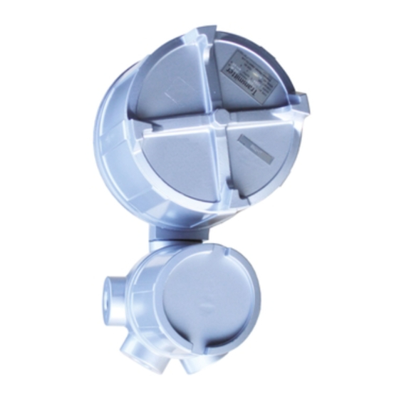
- Page 1 Operating Instructions Analog Transmitter AT1000 AT1 Alarm transmitter for mechanical level gauges BA00414G/08/EN/01.11 71147925...
-
Page 2: Table Of Contents
Disposal ........23 Contact addresses of Endress+Hauser ....23 Installation . -
Page 3: Safety Instructions
• Ensure that all personnel are suitably qualified. • Observe the specifications in the certificate as pipe as national and local regulations. Caution! Changes or modifications not expressly approved by the party responsible for compliance could void the user’s authority to operate the equipment. Endress+Hauser... -
Page 4: Notes On Safety Conventions And Symbols
A terminal which must be connected to earth ground prior to making any other connection to the equipment. Equipotential connection (earth bonding) A connection made to the plant grounding system which may be of type e.g. neutral star or equipotential line according to national or company practice Endress+Hauser... -
Page 5: Identification
Analog Transmitter AT1 2 Identification Identification Device designation 2.1.1 Nameplate The follow technical data are given on the instrument nameplate: Order cord Serial number Measuring range Explosion model Protection class Power Output Analog output Contact output Contact output TIIS approval type Endress+Hauser... -
Page 6: Ordering Information
R 2 xthread NPT3/4 Y Special version, TSP-no. to be spec. Installation Gauge: 1 LT1100/LT1200/LT3100/LT3200 R:300mm low pressure LT version 2 LT1400/LT1600/LT3400/LT3600 R:300mm high pressure LT version 3 LTC2100 L:600mm 4 LTC2230/LTC2240 R:600mm 9 Special version, TSP-no. to be spec. Endress+Hauser... - Page 7 9 Special version, TSP-no. to be spec. Alarm Contact: 0 Not used 1 A = normal 2 B = nomal closed 3 C = transfer contact Colour: 0 Silver 9 Special version, TSP-no. to be spec. AT1- Complete product designation Endress+Hauser...
-
Page 8: Scope Of Delive
It is essential to follow the instructions concerning the unpacking, transport and storage of measuring instruments given in the chapter "Incoming acceptance, transport, storage". The scope of delivery consists of: • Assembled instrument Accompanying documentation: • Operating manual (this manual) Registered trademarks ® HART Registered trademark of HART Communication Foundation, Austin, USA Endress+Hauser... -
Page 9: Installation
3.1.3 Storage Pack the measuring instrument so that is protected against impacts for storage and transport. The original packing material provides the optimum protection for this. The permissible storage temperature is -20°C...+60°C (-4°F...+140°F) Endress+Hauser... -
Page 10: Installation Conditions
3.2.1 Dimensions Flame proof type Alarm output: 0, 2, 4, 6 points locking clamp Main body Cover locking clamp Terminal box Weather proof Alarm output: 0, 2 points, In case of Cable Entry PF(G)3/4,NPT3/4 Main body Cover Terminal box Endress+Hauser... - Page 11 PF(G)3/4 thread PF(G)3/4 thread PF(G)3/4 thread PF(G)1-1/2 thread PF(G)3/4 thread PF(G)1-1/2 gland (G)3/4 TF16-11 gland PF(G)3/4 TF16-11 gland PF(G)3/4 TF16-11 gland PF(G)1 TF22-15 thread NPT1 thread M25 gland PF(G)1-1/4 TF28-20 gland PF(G)3/4 TF16-11 thread NPT3/4 thread NPT3/4 thread NPT3/4 Endress+Hauser...
-
Page 12: Installation With Level Gauge
• When the setting of cam has all finished, set the level on the standard scale by rotating the coupling to match the level setting on the level gauge. Then, close the cover and install it onto the level gauge. Microswitch Com setter Standard scale Scale set boss Alarm Scale Index Alarm cam Scale Com securing screws(2 pieces) Endress+Hauser... - Page 13 If you press the transmitter and the level gauge too firmly against each other, you might break the main shaft and the device will no longer be good for use. Connecting flange of transmitter Level gauge Shaft Transmitter Coupling Coupling pin Endress+Hauser...
- Page 14 Toothed look washer Hexagonal nut Hexagonal nut Shaft Coupling pin Coupling Sprocket wheel O-ring Installation with Medium and high prressure(LT14/16/34/36) Rear of float level gauge Washer Toothed lock washer Hexagonal nut O-ring Hexagonal nut Shaft Coupling pin Coupling Threaded bolt Endress+Hauser...
- Page 15 Analog Transmitter AT1 3 Installation 3.3.1 Tank installation with Float Tank Gauge Transmitter Terminal box Level gauge Sideways Flexible fitting with M-type (both ends) union See cable entry for transmitter Universal fitting Thick steel Endress+Hauser...
-
Page 16: Wiring
DC power supply Level indicator Potentiometer Terminal Converter 4. DC, 0 - 1mA, 0 - 20mA, 0 - 10V, 0 - 1V output (For alarm contact equipped model, refer to 5 also) DC power supply Level indicator Terminal converter Potentiometer Endress+Hauser... - Page 17 4 Wiring 5. With Alarm contacts In case of with contacts in 1, 2, 3, 4, please refer to following circuits. A contact (normal open) Terminal No. B contact (normal close) Terminal No. C contact (transfer contact) Terminal No. Endress+Hauser...
-
Page 18: Operation
• Close the main body cover and install to level gauge. Range of span adjustment is between +0 % and -20% of the maximum value. Converter Zero adjustment screw Span adjustment screw 1 2 3 4 5 6 Endress+Hauser... -
Page 19: Maintenance
Repaires to Ex-approved devices When carrying out repairs to Ex-approved devices, please note the following: • Repairs to Ex-approved devices may only be carried out by trained personnel or by the Endress+Hauser Service. • Comply with the prevailing standards, national Ex-area regulations and certificates. -
Page 20: Troubleshooting
Troubleshooting Spare parts Spare parts are contained in kits. Spare parts which you can order from Endress+Hauser for the Transmitter are shown with their order numbers in the diagram below. For more information on service and spare parts, contact Endress+Hauser. - Page 21 Alarm Output: Not used 2 - point 4 - point 6 - point Installation Gauge: LT1100/LT1200/LT3100/LT3200 R:300mm low pressure LT version LT1400/LT1600/LT3400/LT3600 R:300mm high pressure LT version LTC2100 L:600mm LTC2230/LTC2240 R:600mm Measuring Renge: 1.5m 2.5m 3.5m AT1- Complete product designation Endress+Hauser...
- Page 22 XPN0003 Alarm Assembly Alarm Output: 2 - point 4 - point 6 - point Installation Gauge LT1100/LT1200/LT3100/LT3200 R:300mm low pressure LTversion LT1400/LT1600/LT3400/LT3600 R:300mm high pressure LTversion LTC2100 L:600? LTC2230/LTC2240 R:600? Measuring Range: 1.5m 2.5m 3.5m AT1- Complete product designation Endress+Hauser...
-
Page 23: Troubleshooting
In case of disposal please separate the different components according to their material consistence. Contact addresses of Endress+Hauser The addresses of Endress+Hauser are given on the back cover of this operating manual. If you have any ques- tions, please do not hesitate to contact your Endress+Hauser representative. -
Page 24: Technical Data
440Ω 80Ω 160Ω 250Ω 10 - 50mA Current output (max. impedance) 0 - 1mA 25kΩ 18kΩ 22kΩ 38kΩ 1330Ω 0 - 20mA 1900Ω 900Ω 1100Ω ≥ 500Ω 0 - 10mV Voltage output (min. impedance) 0 - 1V ≥ 30kΩ Endress+Hauser... - Page 25 Erklärung zur Kontamination und Reinigung Please reference the Return Authorization Number (RA#), obtained from Endress+Hauser, on all paperwork and mark the RA# clearly on the outside of the box. If this procedure is not followed, it may result in the refusal of the package at our facility.
- Page 26 Endress + Hauser Japan Co., Ltd. Product Center Yamanashi 862-1 Mitsukunugi Sakaigawa-cho Fuefuki-shi Yamanashi, 406-0846 Japan Phone: ++81 55 266 4964 Fax: ++81 55 266 4969 BA00414G/08/EN/01.11 71147925 FM+SGML 8.0J...
Need help?
Do you have a question about the AT1000 AT1 and is the answer not in the manual?
Questions and answers