Advertisement
Table of Contents
- 1 Step 1: Remove Power from the Controller.
- 2 Step 2: Set the 1769-SM1 Module Configuration Mode Switch.
- 3 Step 3: Assemble the 1769-SM1 Module to the Controller.
- 4 Step 4: Mount the 1769-SM1 Module.
- 5 Step 5: Replacing the Module Within a System.
- 6 Step 6: Connect the Module to the Drive(S).
- 7 Step 7: Ground the Module.
- 8 Step 8: Apply Power.
- Download this manual
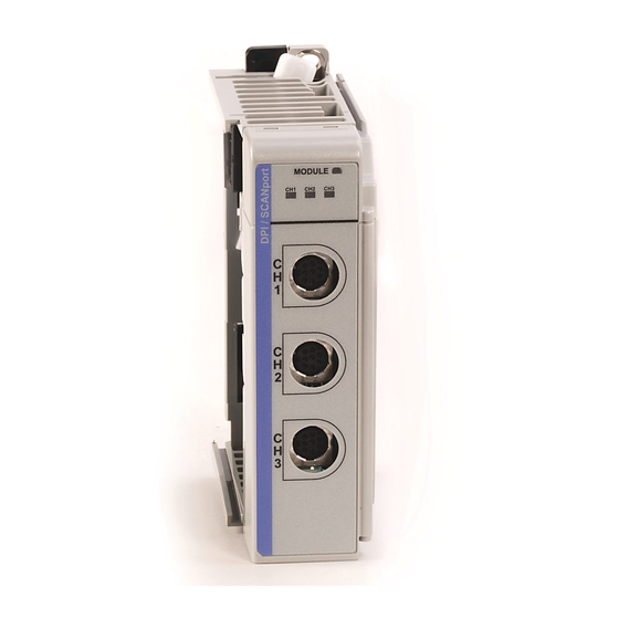
1769-SM1 Compact I/O-to-DPI/SCANport
Network Communication Module
This document explains how to install a 1769-SM1 Compact I/O-to-DPI/SCANport
Network Communication Module into the controller.
ATTENTION: Risk of equipment damage exists. Remove power before
installing or removing the 1769-SM1 module. When you install or remove
!
the module with power applied, an electrical arc may occur. An electrical
arc can cause personal injury or equipment damage by:
• Sending an erroneous signal to your system's field devices, causing
unintended machine motion.
• Causing an explosion in a hazardous environment.
Electrical arcing causes excessive wear to contacts on both the module
and its mating connector. Worn contacts may create electrical resistance.
ATTENTION: Risk of equipment damage exists. The 1769-SM1
module contains ESD (Electrostatic Discharge) sensitive parts that can be
!
damaged if you do not follow ESD control procedures. Static control
precautions are required when handling the module. If you are unfamiliar
with static control procedures, refer to Guarding Against Electrostatic
Damage, Publication 8000-4.5.2.
Related Documentation
Document
1769-SM1 Compact I/O-to-DPI/SCANport
Network Communication Module User
Manual, publication 1769-UM010
Guarding Against Electrostatic Damage,
publication 8000-4.5.2
Wiring and Grounding Guidelines for PWM
AC Drives, publication DRIVES-IN001
Documentation can be obtained online at www.rockwellautomation.com/literature.
To order paper copies of technical documentation, contact your local Rockwell
Automation distributor or sales representative.
For information such as firmware updates and answers to drive-related questions, go
to the Drives Service & Support web site at
on the "Downloads" or "Knowledgebase" link.
Step 1
Remove power from the controller.
Installation Instructions
Description
Provides complete installation, wiring, setup, and
communication information for the 1769-SM1 Network
Communication Module.
Provides static control procedures for protecting
electrostatic discharge sensitive parts.
Guidelines for proper wiring, grounding, and shielding, and
standard practices for noise protection.
www.ab.com/support/abdrives
and click
Advertisement
Table of Contents

Related Manuals for Rockwell Automation 1769-SM1


Summary of Contents for Rockwell Automation 1769-SM1
- Page 1 Network Communication Module into the controller. ATTENTION: Risk of equipment damage exists. Remove power before installing or removing the 1769-SM1 module. When you install or remove the module with power applied, an electrical arc may occur. An electrical arc can cause personal injury or equipment damage by: •...
- Page 2 A. Disconnect power. B. Install the 1769-SM1 module within 6 slots of the power supply. C. Check that the bus lever (item 1) of the 1769-SM1 module is in the unlocked (fully right) position. D. Use the upper and lower tongue-and-groove slots (item 2) to secure the modules together.
- Page 3 Allow at least 140 mm (5.5 in.) of enclosure depth to accomodate the 1769-SM1 module. A. Panel Mounting — Mount the 1769-SM1 module to a panel using two screws per module. Use M4 or #8 panhead screws. Mounting screws are required on every module.
- Page 4 (1.38 in) (1.38 in) (1.38 in) (1.38 in) MODULE 14.7 mm DIN Rail (0.58 in) Center Line Figure 3 1769-SM1 Module with Remote 1769-Based Adapter 50 mm 35 mm 70 mm 35 mm Mounting Hole 28.5 mm (1.97 in) (1.38 in) (2.76 in)
- Page 5 B. Unplug the 1202-C* communications cable from each port (CH1, CH2, CH3) on the 1769-SM1 module. Note each drive and the port to which it is connected. C. Remove the upper and lower mounting screws from the module (or open the DIN latches using a flat-blade screwdriver).
- Page 6 G. Slide the replacement 1769-SM1 module into the open slot. H. Connect the 1769-SM1 module and adjacent modules together by locking (fully left) the bus levers on the 1769-SM1 module and the right-side adjacent module. I. Replace the mounting screws (or snap the module onto the DIN rail).
- Page 7 B. The module is assigned a unique network address by the bus master during initialization. C. Apply power to the drive. When you apply power to the 1769-SM1 module, controller, and network for the first time, the status indicators should be green after an initialization. If the status indicators go red, there is a problem.
- Page 8 Europe/Middle East/Africa: Rockwell Automation, Pegasus Park, De Kleetlaan 12a, 1831 Diegem, Belgium, Tel: (32) 2 663 0600, Fax: (32) 2 663 0640 Asia Pacific: Rockwell Automation, Level 14, Core F, Cyberport 3, 100 Cyberport Road, Hong Kong, Tel: (852) 2887 4788, Fax: (852) 2508 1846 Publication 1769-IN083A-EN-P –...
Need help?
Do you have a question about the 1769-SM1 and is the answer not in the manual?
Questions and answers