Table of Contents
Advertisement
Quick Links
Installation & Operations Manual
36" Emergency Call Station
Emergency Tower Phone
• 2100-TPL Landline 120v Tower
• 2100-TPC Cellular 120v Tower
• 2100-TPV VoIP 120v Tower
• 2100-TPW Wi-Fi VoIP 120v Tower
N56W24720 N. Corporate Circle
Sussex, WI 53089
RP8500040
Made in the USA
Ver. 8
800-451-1460
www.rathcommunications.com
2 Year Warranty
04/21
Advertisement
Table of Contents

Related Manuals for Rath 2100-TPL Landline 120v Tower


Summary of Contents for Rath 2100-TPL Landline 120v Tower
- Page 1 Installation & Operations Manual 36” Emergency Call Station Emergency Tower Phone • 2100-TPL Landline 120v Tower • 2100-TPC Cellular 120v Tower • 2100-TPV VoIP 120v Tower • 2100-TPW Wi-Fi VoIP 120v Tower N56W24720 N. Corporate Circle Sussex, WI 53089 RP8500040 Made in the USA Ver.
-
Page 2: Table Of Contents
Thank you for purchasing RATH’s 120v Tower Phone. We are the largest Emergency Communication Manufacturer in North America and have been in business for over 35 years. We take great pride in our products, service, and support. Our Emergency Products are of the highest quality. -
Page 3: Description
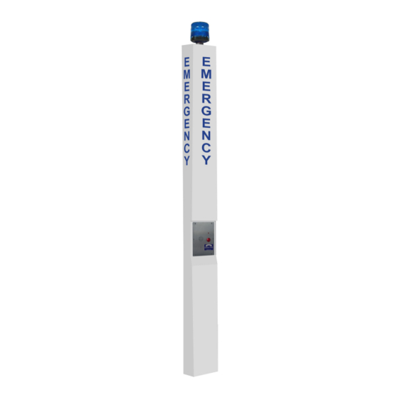
Description Figure 1: Front & Back View Features: • ADA compliant (hands free operation) • LED call status indicator Panel 1 • Powder coated steel construction inside and out • Aluminum access panels powder coated inside and out • Weather and vandal resistant •... -
Page 4: Items Needed
Items Needed for Installation • 1/4” spanner adapter (provided to remove access panels) • Concrete for 16” deep, 2’ diameter • RATH Kit 7476* or 7477** • Adjustable wrench ® • #1 Phillips screwdriver • Analog phone line (if using a Landline) •... - Page 5 LTE Cellular (Units Are Carrier Specific): 1. Open the Cellular Gateway by unscrewing the screw on the left side of the front cover with a Phillips screwdriver and gently pull up on the left side. 2. Insert standard size SIM card (25mm x 15mm) into J4 with the perforated edge first and the gold contact side facing downward.
-
Page 6: Phone Programming
Phone Programming 1. You can program the phone on-site or remotely. Note: Cellular applications cannot be remotely programmed. 2. If programming on-site, remove the face plate. Use the #10 spanner bit provided to remove the 6 security screws. 3. Remove the cover of the NEMA 4 enclosure by loosening the 4 corner screws. On-Site Programming: Step 1: To Begin Program Mode A. -
Page 7: Phone Testing
If you have answered YES to all questions, you have successfully installed and tested the phone. If you answer NO to any question, proceed to the Troubleshooting Section. *RATH recommends the Tower be tested on a regular basis to ensure proper operation. -
Page 8: Troubleshooting
Troubleshooting Problem Possible Cause & Solutions No dial tone when the • Check to make sure the phone line is connected to SmartPhone board. button is pushed: • Verify dial tone and voltage on phone line going into unit. Audio is low from the speaker: •... -
Page 9: Wiring
Wiring Strobe Strobe Constant Enter Record Play / Pause Stop LN G 120v Wago Connector to front plate Phone line to communication source Page 9...
Need help?
Do you have a question about the 2100-TPL Landline 120v Tower and is the answer not in the manual?
Questions and answers