
Related Manuals for Vanco EVMX4016


Summary of Contents for Vanco EVMX4016
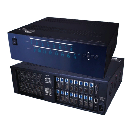
- Page 1 HDBaseT™ 16x16 MATRIX SELECTOR SWITCH (230ft/70m) Vanco Part Number EVMX4016 HDBaseT 16x16 Matrix Selector Switch (230ft/70m) www.vanco1.com • 800.626.6445...
- Page 2 DEAR CUSTOMER Thank you for purchasing this product. For optimum performance and safety, please read these instructions carefully before connecting, operating or adjusting this product. Please keep this manual for future reference. This product is 100% inspected and tested in the United States to verify HDMI performance parameters.
- Page 3 (sold separately). Features additional HDMI output per HDBaseT output for flexibility or mirroring capability, able to handle up to 32 displays. With an output bandwidth of 6.75 Gbps, the EVMX4016 is capable of high definition video and multi-channel audio distribution with simple control using the front panel or remotely via IR Receivers at display locations.
- Page 4 HDBaseT 16x16 Matrix Selector Switch (230ft/70m) Part # EVMX4016 • Allows up to 16 HDMI sources to be distributed simultaneously to up to 16 displays • 16 additional HDMI outputs for flexibility or mirroring capability; allows for connection of up to 32 displays or the ability to create a larger distribution system by cascading or daisy chaining •...
-
Page 5: Specifications
Operation temperature ..........32-104 degrees F Storage temperature..........-4 - 140 degrees F Relative humidity ............20-90% RH (no condensation) PACKAGE CONTENTS • (1) EVMX4016 HDBaseT 16x16 Matrix Selector Switch • (17) IR Receiver (RX) • (16) IR Blaster (TX) •... -
Page 6: Panel Descriptions
PANEL DESCRIPTIONS 1. Power Switch 2. 7-segment LED: for output 1-16 status 3. Source Status: Input source indicator LED 4. IR SENSOR: IR sensor for receiving the IR commands from IR remote 5. Push Button: Select the output and input 6. - Page 7 PANEL DESCRIPTIONS RECEIVER - Part#EVRX3000 (Sold Separately) 1. 24V DC: Connect to 24V DC power supply (optional) 2. LED: Power indicator 3. HDMI OUT: Connects to an HDMI display with an HDMI male-male cable 4. IR Blaster: Infrared 3.5mm socket for plugging in the extension cable of IR blaster 5.
- Page 8 EDID EDID management allows for EDID learning or to pre-set an EDID to encourage a “handshake” between the display and source. The EDID learning function is only necessary whenever any display on the HDMI output port is not outputting audio and video properly. Because the HDMI source devices and displays may have various level of capability in playing audio and video, the general principle is that the source device will output the lowest standards in audio format and video resolutions to be acceptable among all HDMI displays connected.
- Page 9 OPERATION CONTROL - FRONT PANEL 1. INPUT/OUTPUT MAPPING • Use the “LEFT” or “RIGHT“ push button to select the output desired to switch sources • Use the “UP” or “DOWN“ push button to select the specific source. • Press “SET” to confirm 800.626.6445...
-
Page 10: Button Function
OPERATION CONTROL - IR REMOTE CONTROL BUTTON FUNCTION Power on the matrix switcher Standby mode PRESET Preset mapping mode SAVE Save current mapping mode Number buttons 1-9 Select a number Select a number Transfer key TAKE Trigger the previous setting Mute Turn off/Mute the selected Output SWITCH... - Page 11 OPERATION CONTROL - Input/output Switch Push the corresponding button on the remote to select Input & Output port Operation Procedure 7-Segment LED IN/OUT Switch Switch + number(input) + To + number(output) + Take 1.Press “SWITCH” button Ex: Input 3 To Output 4 2.Press number key “3”...
- Page 12 OPERATION CONTROL - Input/output Switch Continued Learn default EDID Default EDID + number (1-16 default EDID) + To + number(input) + Take 1.Press “DEFAULT EDID” button 2.Press number key “2” to select default EDID Ex: Default EDID 2 Input 3.Press “To” button 4.
- Page 13 1.Press “LEARN” button Ex: Learn Output 2 Input 3 2.Press number key “2” to select Output 3.Press “To” button 4. Press number key “3” to select Input 5.Press “TAKE” button 0 (success) F (fail) Learn + number(output) + To + all(input) + Take 1.Press “LEARN”...
-
Page 14: Lan Port
OPERATION CONTROL - SOFTWARE CONTROL THROUGH RS-232 AND LAN PORT 1. System Requirement 1) OS Information: MS WinXP/7 2) Baud rates: 9600 3) Software size: 3 MB 4) Minimum RAM requirement: 256 MB OPERATION CONTROL – Software control through RS-232 I/O Routing Button Rename I/O Button EDID Button... - Page 15 1. Input Selection and Mapping I/O: Select the input Click “Send” to change the I/O setting Save Mapping: Select Mapping(1-16) Click “Save” button to save current mapping Preset Mapping: Select Mapping(1-16) Click “Recall” button to recall previous mapping which are saved 800.626.6445...
- Page 16 2. Rename I/O Button Rename I/O: Rename output name Rename input name Rename Mapping: Rename Mapping name www.vanco1.com...
- Page 17 3. EDID BUTTON Learn EDID from Default Select Default EDID(1-16 Default EDID) Select Input Click “Send” button to learn default EDID Learn EDID From Display Select output Select Input Click “Send” button to learn display EDID Load EDID File to Input Select Input Click “Load”...
- Page 18 4. NETWORK Save Setting Save the IP address which is manually entered Read Setting: Read the IP address from the device ** The default IP address is 192.168.1.111 www.vanco1.com...
-
Page 19: System Button
5. SYSTEM BUTTON 1) Version: => To get the F/W version information 2) Factory Reset 3) Help => To view the steps of the firmware update 4) Firmware Update Main Board 5) Firmware Update Valens 6) Firmware Update DB Board 7) Firmware Update Web IC 800.626.6445... -
Page 20: Connection Status
6. COM PORT SELECTION Click “ ” button to select COM Port 7. CONNECTION STATUS Connected Status: Connecting Status: Disconnected Status: 8. CONNECT/DISCONNECT Click this button “ ” to change connection status www.vanco1.com... - Page 21 9. RS-232 Click “ ” button to switch to RS-232 function. If RS-232 is connected, the button emit to show that RS-232 is connected 10. ETHERNET Click “ ” button to switch to Ethernet function If Ethernet is connected, the button will emit to show that ethernet is connected 800.626.6445...
- Page 22 OPERATION CONTROL - WEB INTERFACE CONTROL The default IP address: 192.168.1.111 Account: admin Password: matrix 1. Input/Output Routing 2. Setting 3. EDID 4. Refresh Input/Output and Read Input/Output Name 1) I/O Routing 1) I/O: a) Select the input b) Click “Send” to change the I/O setting 2) Save Mapping: a) Select Mapping(1-16)
- Page 23 2) Settings 1) Rename I/O: a) Rename output name b) Rename input name 2) Rename Mapping: a) Rename Mapping name 3) Password change: (the password has to be 6 characters) a) Key in “old password” b) Key in “new password” c) Key in “new password”...
- Page 24 3) EDID 1) Learn EDID from Default a) Select Default EDID(1-16 Default EDID) b) Select Input c) Click “Send” button to learn default EDID 2) Learn EDID From Display a) Select output b) Select Input c) Click “Send” button to learn display EDID www.vanco1.com...
-
Page 25: Connection Diagram
CONNECTION DIAGRAM 800.626.6445... -
Page 26: Connect And Operate
CONNECT AND OPERATE 1. Connect up to 16 sources such as a Blu-Ray Player, game console, A/V Receiver, Cable or Satellite Receiver, etc. to the HDMI inputs on the unit. Do not hotplug! Insert and extract cables carefully with the power SWITCHED OFF. Connecting and disconnecting while the unit is powered can result in damage to circuitry. -
Page 27: Ir Pass-Through
IR Blaster TX IR Receiver RX IR BLASTER (EV-IRTX) Plug IR Blaster into IR TX port of matrix unit (EVMX4016; place blaster in front of the IR eye of the corresponding source. IR RECEIVER (EV-IRRX) Plug IR Receiver into IR RX port of matrix unit (EVMX4016); place receiver at or near corresponding display. - Page 28 NOTICE 1. Vanco High Speed HDMI cables are strongly recommended for use with this product to ensure best results. 2. Incorrect placement of IR Blaster and Receiver may result in the failure of the unit. Please check carefully before plugging in the IR accessories into the respective IR sockets.
-
Page 29: Troubleshooting
HDMI cables disconnected, turn on the source and plug in the HDMI cable into it’s output, then power up the Vanco unit and plug the HDMI cable into it’s input, finally turn on the display and plug the HDMI cable from the receiver into it. This activates all of the devices in corresponding order and results in a signal being plugged into a device that is on and will attempt to connect the signal. -
Page 30: Safety And Notice
SAFETY AND NOTICE The EVMX4016 has been tested for conformance to safety regulations and requirements, and has been certified for international use. However, like all electronic equipments, the EVMX4008 should be used with care. Please read and follow the safety instructions to protect yourself from possible injury and to minimize the risk of damage to the unit. -
Page 31: Technical Support
TECHNICAL SUPPORT In case of problems, please contact Vanco Technical Support by dialing 1-800-626-6445. You can also email technical support issues to info@vanco1.com When calling, please have the Model Number, Serial Number (affixed to the bottom of the unit) and Invoice available for reference during the call. - Page 32 ® Vanco International 506 Kingsland Drive Batavia, Illinois 60510 call: 800.626.6445 fax: 630.879.9189 visit: www.vanco1.com...
Need help?
Do you have a question about the EVMX4016 and is the answer not in the manual?
Questions and answers