
Related Manuals for Siemens SIMATIC NET RUGGEDCOM RS416


Summary of Contents for Siemens SIMATIC NET RUGGEDCOM RS416
- Page 1 Installation Manual SIMATIC NET Rugged Ethernet Switches RUGGEDCOM RS416 Edition 04/2021 https://www.siemens.com...
- Page 2 Preface Introduction Installing Device SIMATIC NET Device Management Rugged Ethernet Switches RUGGEDCOM RS416 Communication Ports Technical Specifications Installation Manual Certification 04/2021 C79000-G8976-1018-10...
- Page 3 Note the following: WARNING Siemens products may only be used for the applications described in the catalog and in the relevant technical documentation. If products and components from other manufacturers are used, these must be recommended or approved by Siemens. Proper transport, storage, installation, assembly, commissioning, operation and maintenance are required to ensure that the products operate safely and without any problems.
-
Page 4: Table Of Contents
Accessing Documentation ....................... v Registered Trademarks ......................v Warranty ..........................v Training ..........................vi Customer Support ........................vi Contacting Siemens ....................... vii Introduction ........................... 1 Feature Highlights ....................1 Description ......................2 Required Tools and Materials ................. 4 Decommissioning and Disposal ................4 Cabling Recommendations .................. - Page 5 Table of Contents Fiber Optic Ethernet Ports ................... 24 Serial Ports ......................25 BNC Ports ......................28 Connecting Multiple RS485 Devices ..............29 Technical Specifications ...................... 31 Power Supply Specifications ................31 Failsafe Relay Specifications ................31 Copper Ethernet Port Specifications ..............31 Fiber Optic Ethernet Port Specifications ...............
-
Page 6: Preface
Warranty Siemens warrants this product for a period of five (5) years from the date of purchase, conditional upon the return to factory for maintenance during the warranty term. This product contains no user-serviceable parts. Attempted service by unauthorized personnel shall render all warranties null and void. -
Page 7: Training
Siemens Sales representative. Customer Support Customer support is available 24 hours, 7 days a week for all Siemens customers. For technical support or general information, contact Siemens Customer Support through any of the following methods: Online Visit http://www.siemens.com/automation/support-request... -
Page 8: Contacting Siemens
Preface Contacting Siemens • Contact a local Siemens representative from Sales, Technical Support, Training, etc. • Ask questions or share knowledge with fellow Siemens customers and the support community Contacting Siemens Address Siemens AG Industry Sector 300 Applewood Crescent Concord, Ontario... - Page 9 Preface Contacting Siemens viii RUGGEDCOM RS416 Installation Manual, 04/2021, C79000-G8976-1018-10...
-
Page 10: Introduction
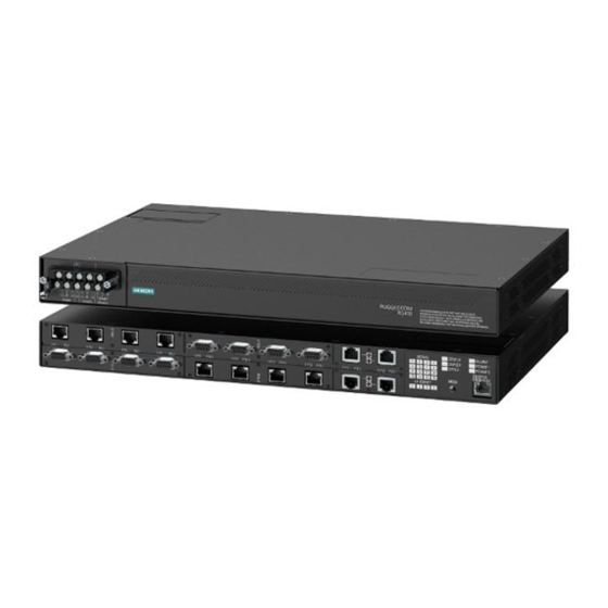
Introduction The RUGGEDCOM RS416 is an industrially hardened serial device server with an integrated, fully managed, Ethernet switch, designed to operate reliably in electrically harsh and climatically demanding environments. Featuring a modular design that can support IEEE 1588 and IRIG-B time synchronization, up to 16 serial ports and up to four Ethernet ports, the RUGGEDCOM RS416 is able to interconnect and synchronize multiple types of intelligent electronic devices (IEDs). -
Page 11: Description
Introduction 1.2 Description • Converts Modbus RTU to Modbus • Supports multiple Modbus masters • Converts DNP3.0 to DNP over UDP/TCP Ethernet Ports • Integrated Ethernet switch • Copper or fiber options • Supports IEEE 1588 v2 • Non-blocking, store and forward switching IRIG-B Option •... - Page 12 Introduction 1.2 Description Serial Ports Fiber Optic Ethernet and/or BNC (Optional) Ports Port Status Indicator LEDs Display Mode Indicator LEDs Mode Button Alarm Indicator LED Power Module Indicator LEDs RS-232 Serial Console Port (RJ45) Figure 1.1 RUGGEDCOM RS416 Communication Ports Ports for communicating with other devices or accessing the RUGGEDCOM RUGGEDCOM RS416 operating system are described "Communication Ports (Page 23)".
-
Page 13: Required Tools And Materials
Introduction 1.3 Required Tools and Materials Power Module Indicator LEDs The power module indicator LEDs indicate the status of the power modules. Color Description Green The power supply is supplying power Power supply failure No power supply is installed RS-232 Console Port The serial console port is for interfacing directly with the device and accessing initial management functions. -
Page 14: Cabling Recommendations
Siemens also does not recommend using copper Ethernet ports to interface with devices in the field across distances that could produce high levels of ground potential rise (i.e. greater than 2500 V), during line-to-ground fault conditions. -
Page 15: 1.6.1 Supported Time Synchronization Sources
Introduction 1.6.1 Supported Time Synchronization Sources TTL OUT Port TTL IN Port Figure 1.2 PTP Module For more information about the BNC ports, refer to "BNC Ports (Page 28)". 1.6.1 Supported Time Synchronization Sources The following time synchronization sources are supported by the RUGGEDCOM RS416, with or without the PTP card: Synchronization Source Without PTP Card... -
Page 16: Ttl Outputs
Introduction 1.6.2 TTL Outputs Every Ethernet port on the RUGGEDCOM RS416 supports IEEE 1588. For more information, refer to "IEEE 1588 Support (Page 7)". 1.6.2 TTL Outputs The PTP card provides a TTL (Transistor-Transistor Logic) output. The TTL OUT port supports the IRIG-B PWM and PPS signal formats. Enabling/ disabling the output port and selecting the signal format is controlled through the RUGGEDCOM RS416 operating system. - Page 17 Introduction 1.6.3 IEEE 1588 Support • Peer-to-Peer Slave Clock • Peer-to-Peer Master Clock RUGGEDCOM RS416 Installation Manual, 04/2021, C79000-G8976-1018-10...
-
Page 18: Installing Device
This product contains no user-serviceable parts. Attempted service by unauthorized personnel shall render all warranties null and void. Changes or modifications not expressly approved by Siemens AG could invalidate specifications, test results, and agency approvals, and void the user's authority to operate the equipment. -
Page 19: General Procedure
Inspect the package for damage before opening it. Visually inspect each item in the package for any physical damage. Verify all items are included. Note If any item is missing or damaged, contact Siemens for assistance. RUGGEDCOM RS416 Installation Manual, 04/2021, C79000-G8976-1018-10... -
Page 20: Mounting The Device
Installing Device 2.3 Mounting the Device Mounting the Device The RUGGEDCOM RS416 is designed for maximum mounting and display flexibility. It can be equipped with connectors that allow it to be installed in a 48 cm (19 in) rack, 35 mm (1.4 in) DIN rail, or directly on a panel. IMPORTANT Heat generated by the device is channeled outwards from the enclosure. -
Page 21: 2.3.2 Mounting The Device On A Din Rail
Installing Device 2.3.2 Mounting the Device on a DIN Rail Make sure the rack mount adapters are installed on the correct side of the chassis. Note The chassis features multiple mounting holes, allowing the rack mount adapters to be installed up to 25 mm (1 in) from the face of the device. Rear Front Rack Mount Adapter... -
Page 22: 2.3.3 Mounting The Device To A Panel
Installing Device 2.3.3 Mounting the Device to a Panel To mount the device to a DIN rail, do the following: Align the adapters with the DIN rails and slide the device into place. Panel/DIN Rail Adapter DIN Rail Screw Figure 2.2 DIN Rail Mounting Install one of the supplied screws on either side of the device to secure the adapters to the DIN rails. -
Page 23: Connecting The Failsafe Alarm Relay
Installing Device 2.4 Connecting the Failsafe Alarm Relay To mount the device to a panel, do the following: Place the device against the panel and align the adapters with the mounting holes. Screw Panel/DIN Rail Adapter Figure 2.3 Panel Mounting Install the supplied screws to secure the adapters to the panel. Connecting the Failsafe Alarm Relay The failsafe relay can be configured to latch based on alarm conditions. -
Page 24: Grounding The Device
Installing Device 2.5 Grounding the Device Screw-Type Terminal Block Pluggable Terminal Block Normally Open Terminal Common Terminal Normally Closed Terminal Figure 2.4 Failsafe Alarm Relay Wiring Grounding the Device The RUGGEDCOM RS416 chassis ground terminal uses a #6-32 screw. It is recommended to terminate the ground connection with a #6 ring lug and torque it to 1.7 N·m (15 lbf·in). -
Page 25: Connecting Power
Installing Device 2.6 Connecting Power Connecting Power The RUGGEDCOM RS416 supports single or dual redundant high AC and/or low DC power supplies. The RUGGEDCOM RS416 can be equipped with either a screw-type or pluggable terminal block, which provides power to both internal power modules. The screw- type terminal block is installed using Phillips screws and compression plates, allowing either bare wire connections or crimped terminal lugs. - Page 26 Installing Device 2.6.1 Connecting AC or DC Power NOTICE Electrical hazard – risk of damage to equipment Do not connect AC power cables to a DC power supply terminal block. Damage to the power supply may occur. IMPORTANT Each internal power module is labeled POWER 1 or POWER 2. Make sure to connect the power supply to the corresponding internal power module.
-
Page 27: 2.6.2 Wiring Examples
Installing Device 2.6.2 Wiring Examples Connect the negative wire from the power source to the negative/neutral (-/N) terminal on the terminal block. Install the supplied metal jumper between terminals 2, 4 and 6 to connect the surge ground terminals to the chassis ground terminal. The surge ground terminals are used as the ground conductor for all surge and transient suppression circuitry internal to the unit. - Page 28 Installing Device 2.6.2 Wiring Examples Figure 2.8 Single DC Power Supply Figure 2.9 Dual AC Power Supply RUGGEDCOM RS416 Installation Manual, 04/2021, C79000-G8976-1018-10...
- Page 29 Installing Device 2.6.2 Wiring Examples Figure 2.10 Dual DC Power Supply Figure 2.11 Dual AC/DC Power Supply RUGGEDCOM RS416 Installation Manual, 04/2021, C79000-G8976-1018-10...
-
Page 30: Device Management
Device Management This section describes how to connect to and manage the device. Connecting to the Device The following describes the various methods for accessing the RUGGEDCOM RS416 console and Web interfaces on the device. For more detailed instructions, refer to the RUGGEDCOM RS416 User Guide for the RUGGEDCOM RS416. -
Page 31: Configuring The Device
Device Management 3.2 Configuring the Device Communication Ports Connect any of the available Ethernet ports on the device to a management switch and access the RUGGEDCOM RS416 console and Web interfaces via the device's IP address. For more information about available ports, refer to "Communication Ports (Page 23)". -
Page 32: Communication Ports
Communication Ports The RUGGEDCOM RS416 can be equipped with various types of communication ports to enhance its abilities and performance. Each communication port type has a specific place in the RUGGEDCOM RS416 chassis. Slot 1 Slot 2 Slot 3 Slot 4 Slot 5 Slot 6 Figure 4.1... -
Page 33: Fiber Optic Ethernet Ports
Communication Ports 4.2 Fiber Optic Ethernet Ports WARNING Electric shock hazard – risk of serious personal injury and/or equipment interference If shielded cables are used, make sure the shielded cables do not form a ground loop via the shield wire and the RJ45 receptacles at either end. Ground loops can cause excessive noise and interference, but more importantly, create a potential shock hazard that can result in serious injury. -
Page 34: Serial Ports
Communication Ports 4.3 Serial Ports Tx Connector Tx Connector Rx Connector Rx Connector Figure 4.4 LC Port Figure 4.3 MTRJ Port Tx Connector Tx Connector Rx Connector Rx Connector Figure 4.5 SC Port Figure 4.6 ST Port For specifications on the available fiber optic Ethernet ports, refer to "Fiber Optic Ethernet Port Specifications (Page 32)". - Page 35 Communication Ports 4.3 Serial Ports The following is the pin-out description for ST, DB9 and RJ45 serial ports: Fiber Serial Port Tx Connector Rx Connector Figure 4.7 ST Port Serial DB9 Port Mode RS232 DCE RS485 RS422 TX/RX+ ...
- Page 36 Communication Ports 4.3 Serial Ports Serial DB9 Port with IRIG-B Support Mode RS232 DTE RS485 RS422 TX/RX+ IRIG-B+ Common (Isolated) Ground Common (Isolated) Ground TX/RX- Figure 4.9 Serial DB9 Port Pin Configuration Common (Isolated) Ground Shield Chassis Ground In RS232 DTE mode, ports transmit to DTE devices on pin 2 and receive from DTE on pin 3.
-
Page 37: Bnc Ports
Communication Ports 4.4 BNC Ports Serial RJ45 Port with IRIG-B Support RS232 RS485 RS422 Mode Mode Mode +IRIG-B Common (Isolated) Ground Figure 4.11 Serial RJ45 Port Pin Common (Isolated) Ground Configuration TX/RX+ TX/RX- Shield Chassis Ground In RS232 mode, the RJ45 ports conform to EIA-561 DTE, which transmit on TXD and receive on RXD. -
Page 38: Connecting Multiple Rs485 Devices
Communication Ports 4.5 Connecting Multiple RS485 Devices • Red – Error • Off – No signal detected Connecting Multiple RS485 Devices Each RS485 port can communicate with multiple RS485 devices by wiring devices together in sequence over a single twisted pair with transmit and receive signals on the same two wires (half duplex). - Page 39 Communication Ports 4.5 Connecting Multiple RS485 Devices RS485 Devices (32 Total) Figure 4.13 Recommended RS485 Wiring RUGGEDCOM RS416 Installation Manual, 04/2021, C79000-G8976-1018-10...
-
Page 40: Technical Specifications
Technical Specifications This section provides important technical specifications related to the device and available modules. Power Supply Specifications Input Range Maximum Power Internal Fuse Isolation Power Supply Type Rating Minimum Maximum Consumption 12 VDC 10 VDC 36 VDC 6.3 A(F) 24 VDC 1.5 kVDC 48 VDC... -
Page 41: Fiber Optic Ethernet Port Specifications
Technical Specifications 5.4 Fiber Optic Ethernet Port Specifications Maximum Distance 100 m (328 ft) Isolation 1.5 kV Auto-negotiating. Shielded or unshielded. Auto-crossover and auto-polarity. Typical distance. Dependent on the number of connectors and splices. RMS 1 minute. Fiber Optic Ethernet Port Specifications The following details specifications for the fiber optic Ethernet ports that can be equipped on the RUGGEDCOM RS416. -
Page 42: Serial Port Specifications
Technical Specifications 5.5 Serial Port Specifications Serial Port Specifications This section details specifications for ports that can be equipped on the RUGGEDCOM RS416. Copper Serial Ports Baud Rate Connector Isolation 1200 to 230400 kbps 2.5 kV 1200 to 230400 kbps RJ45 2.5 kV 1200 to 230400 kbps 2.5 kV... -
Page 43: Mechanical Specifications
Technical Specifications 5.8 Mechanical Specifications Ambient Relative Humidity 5% to 95% Maximum Altitude 2000 m (6562 ft) Measured from a 30 cm (12 in) radius surrounding the center of the enclosure. Non-condensing. Mechanical Specifications Weight 4.5 kg (10 lbs) Ingress Protection IP20 Enclosure 18 AWG Galvanized Steel... - Page 44 Technical Specifications 5.9 Dimension Drawings 479.30 11.68 461.01 21.08 32.64 4.57 Figure 5.2 Rack Mount Dimensions 486.4 476.3 10.4 11.7 Figure 5.3 Panel and DIN Rail Mount Dimensions RUGGEDCOM RS416 Installation Manual, 04/2021, C79000-G8976-1018-10...
- Page 45 Technical Specifications 5.9 Dimension Drawings RUGGEDCOM RS416 Installation Manual, 04/2021, C79000-G8976-1018-10...
-
Page 46: Certification
Information Technology Equipment - Safety - Part 1: General Requirements The device is marked with a CSA symbol that indicates compliance with both Canadian and U.S. requirements. A copy of the CSA Certificate of Compliance is available via Siemens Industry Online Support at https://support.industry.siemens.com/cs/ww/en/view/109476557. 6.1.2... -
Page 47: 6.1.3 Fcc
Safety of Laser Products – Equipment Classification and Requirements The device is marked with a CE symbol and can be used throughout the European community. A copy of the EU Declaration of Conformity is available via Siemens Industry Online Support at https://support.industry.siemens.com/cs/ww/en/view/109475474. 6.1.3 This device has been tested and found to comply with the limits for a Class A digital device, pursuant to Part 15 of the FCC Rules. -
Page 48: Ised
Title 21 Code of Federal Regulations (CFR) – Chapter I – Sub-chapter J – Radiological Health 6.1.5 ISED This device is declared by Siemens AG to meet the requirements of the following ISED (Innovation Science and Economic Development Canada) standard: • CAN ICES-3 (A)/NMB-3 (A) 6.1.6... -
Page 49: 6.1.8 Rohs
Certification 6.1.8 RoHS 6.1.8 RoHS This device is declared by Siemens AG to meet the requirements of the following RoHS (Restriction of Hazardous Substances) directives for the restricted use of certain hazardous substances in electrical and electronic equipment: • China RoHS 2... - Page 50 ports AC Power 2 kV ports HV Impulse Signal ports 5 kV (Fail-Safe Relay Output) DC Power 5 kV ports AC Power 5 kV ports Siemens specified severity level. RUGGEDCOM RS416 Installation Manual, 04/2021, C79000-G8976-1018-10...
- Page 51 Certification 6.2 EMC and Environmental Type Tests IEEE 1613 EMC Immunity Type Tests Note The RUGGEDCOM RS416 meets Class 2 requirements for an all-fiber configuration and Class 1 requirements for copper ports. Description Test Levels Enclosure Contact ± 8 kV Enclosure Air ±...
- Page 52 Further Information Siemens RUGGEDCOM https://www.siemens.com/ruggedcom Industry Online Support (service and support) https://support.industry.siemens.com Industry Mall https://mall.industry.siemens.com Siemens AG Digital Industry Process Automation Postfach 48 48 90026 NÜRNBERG GERMANY...
Need help?
Do you have a question about the SIMATIC NET RUGGEDCOM RS416 and is the answer not in the manual?
Questions and answers