
Related Manuals for Beckhoff PS1061-2410-0000


Summary of Contents for Beckhoff PS1061-2410-0000
- Page 1 Documentation | EN PS1061-2410-0000 Power supply 24 V DC, 10 A, 1 phase, AC 200-240 V 2021-06-16 | Version: 1.0...
-
Page 3: Table Of Contents
Series connection .......................... 28 Parallel use to increase power ...................... 29 Parallel use for 1+1 redundancy...................... 29 Operation on two phases......................... 30 Use in a tightly sealed enclosure ..................... 30 5 Appendix .............................. 31 Accessories ............................. 31 Documentation issue status ...................... 33 Support and Service ........................ 34 PS1061-2410-0000 Version: 1.0... - Page 4 Table of contents Version: 1.0 PS1061-2410-0000...
-
Page 5: Overview
• Full power between -10 °C and +55 °C • Including DC-OK relay contact The PS1061-2410-0000 is a 1-phase 24 V power supply with an output current of 10 A and an output power of 240 W. The device has an input voltage range of AC 200 - 240 V and input inrush current limitation. -
Page 6: Foreword
, XTS and XPlanar are registered trademarks of and licensed by Beckhoff Automation GmbH. Other designations used in this publication may be trademarks whose use by third parties for their own purposes could violate the rights of the owners. Patent Pending... -
Page 7: Safety Instructions
All the components are supplied in particular hardware and software configurations appropriate for the application. Modifications to hardware or software configurations other than those described in the documentation are not permitted, and nullify the liability of Beckhoff Automation GmbH & Co. KG. Personnel qualification This description is only intended for trained specialists in control, automation and drive engineering who are familiar with the applicable national standards. - Page 8 Foreword Safety instructions and installation requirements for the PS1061-2410-0000 power supply DANGER Danger of electric shock, fire, injuries, injuries resulting in death! • Do not use the power supply without proper grounding (protective conductor). Use the terminal at the in- put terminal strip for the earth connection, not one of the screws on the housing.
- Page 9 • The device is suitable for supply from TN, TT or IT networks. The continuous voltage between the input terminal and the PE potential must not exceed 300 Vac. • The device is designed for altitudes up to 5000 m. A reduction of the output current is required above 2000 m. PS1061-2410-0000 Version: 1.0...
-
Page 10: Terminology And Abbreviations
Unless otherwise specified, AC 230 V parameters are valid at a mains frequency of 50 Hz. A keyword indicating a choice without implied preference. shall A keyword indicating a mandatory requirement. should A keyword indicating a choice with a clearly preferred method of implementation. Version: 1.0 PS1061-2410-0000... -
Page 11: Technical Data, Mounting, Wiring
*) The power factor is the ratio of real (or active) power to apparent power in an AC circuit. **) The peak factor is the mathematical ratio of the peak value to the RMS value of the input current waveform. Fig. 1: Input voltage range; switch-on behavior definitions PS1061-2410-0000 Version: 1.0... - Page 12 Technical data, mounting, wiring Fig. 2: Input current over output current; power factor over output current Version: 1.0 PS1061-2410-0000...
-
Page 13: Dc Input
Technical data, mounting, wiring DC input Do not use the power supply unit with DC input voltages! PS1061-2410-0000 Version: 1.0... -
Page 14: Input Inrush Current
2.5 A At +40 °C, cold start Fig. 3: Input inrush current surge, typical behavior 230 Vac input, 24 V 10 A output, 25 °C ambient temperature; Input inrush current, zoomed in to the first peak, 230 Vac input, 24 V 10 A output, 25 °C ambient temperature Version: 1.0 PS1061-2410-0000... -
Page 15: Output
This is the maximum output voltage that can occur in the end position of the potentiometer in clockwise direction due to tolerances. It is not a guaranteed value that can be achieved. Linear derating between +55 °C and 70 °C ambient temperature Fig. 4: Output voltage over output current, typ. PS1061-2410-0000 Version: 1.0... -
Page 16: Hold-Up Time
At 24 V, 5 A, see Fig. Hold-up time over input voltage Typ. 33 ms At 24 V, 10 A, see Fig. Hold-up time over input voltage Min. 25 ms At 24 V, 10 A, see Fig. Hold-up time over input voltage Fig. 5: Hold-up time over input voltage; switch-off behavior, definitions Version: 1.0 PS1061-2410-0000... -
Page 17: Dc-Ok Relay Contact
Contact load capacity Maximum 60 Vdc 0.3 A, 30 Vdc 1 A, 30 Vac 0.5 A, ohmic load Minimum permissible load: 1 mA at 5 Vdc Insulation voltage see the table in chapter Dielectric strength [} 25] Fig. 6: Behavior of the DC-OK relay contact PS1061-2410-0000 Version: 1.0... -
Page 18: Efficiency And Losses
50 % of the nominal load for a further 25 % of the time, 75 % of the nominal load also for 25 % of the time and 100 % of the nominal load during the remaining time. Fig. 7: Efficiency over output current; losses over output current Version: 1.0 PS1061-2410-0000... -
Page 19: Life Expectancy
1,000,000 h means that statistically, if 10,000 devices are installed in the field, one device will fail every 100 hours. However, it is not possible to determine whether the failed device has run for 50,000 hours or only 100 hours. PS1061-2410-0000 Version: 1.0... -
Page 20: Terminals And Wiring
• Do not use the device without PE connection. • Make sure that all single wires of a strand are connected to the terminal! • Unused terminals should be tightened firmly. • Ferrules are permitted. 3.10 Functional wiring diagram Fig. 8: Functional wiring diagram Version: 1.0 PS1061-2410-0000... -
Page 21: Front Side And Operating Elements
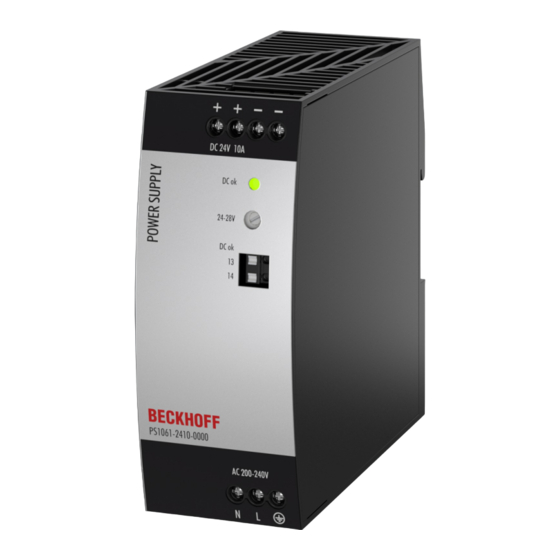
Technical data, mounting, wiring 3.11 Front side and operating elements Fig. 9: PS1061-2410-0000, front Input terminals (screw terminals) Designation (A) Description Mains input N Mains input L PE input (protective conductor) Output terminals (screw terminals) Designation (B) Description two identical positive poles, positive output... -
Page 22: Emc
EN 55011, EN 55022 Class B Harmonic input current EN 61000-3-2 not met Voltage fluctuations, flicker EN 61000-3-3 Fulfilled, tested with constant current loads, non-pulsing Switching frequencies Main converter 75 to 120 kHz Dependent on output voltage and load Version: 1.0 PS1061-2410-0000... -
Page 23: Environment
Do not energize when condensation is present! Tested in conjunction with DIN rails according to EN 60715 with a height of 15 mm and a thickness of 1.3 mm and standard installation position. Fig. 10: Output current over ambient temperature; output current over installation altitude PS1061-2410-0000 Version: 1.0... -
Page 24: Protective Functions And Safety Features
Protection class According to IEC 61140 PE (protective conductor) connection required Touch current (leakage current) Typ. 0.35 mA / 0.73 mA At 230 Vac, 50 Hz, TN, TT / IT network Max. 0.46 mA / 0.97 mA At 264 Vac, 50 Hz, TN, TT / IT network Version: 1.0 PS1061-2410-0000... -
Page 25: Dielectric Strength
Fig. 11: Dielectric strength Type test 60 s 2500 Vac 3000 Vac 500 Vac 500 Vac Component test 5 s 2500 Vac 2500 Vac 500 Vac 500 Vac Field test 5 s 2000 Vac 2000 Vac 500 Vac 500 Vac Cut-off current setting for field > 10 mA > 10 mA > 15 mA > 1 mA testing PS1061-2410-0000 Version: 1.0... -
Page 26: Declaration Of Conformity And Approvals
Trade conformity assessment for England, Scotland and Wales The UKCA mark indicates conformity with the UK Statutory Instruments 2016 No. 1101 (LVD) 2016 No. 1091 (EMC) and 2012 No. 3032 (RoHS) UL Certificate, UL61010-1/2-201 Applicable for US and Canada Version: 1.0 PS1061-2410-0000... -
Page 27: Dimensions And Weight
Vicat softening temperature specified at 149 °C according to ASTM D1525 Installation See chapter on Safety instructions and installation requirements [} 9] clearances Ingress protection Small parts such as screws, nuts etc. with a diameter of more than 4 mm Fig. 12: PS1061-2410-0000 front/side view PS1061-2410-0000 Version: 1.0... -
Page 28: Application Notes
Power supplies connected in series should only be used in the standard installation position (terminals on the underside of the device). Remember that leakage current, electromagnetic interference, inrush current and harmonics increase when using multiple power supplies. Fig. 13: Series connection Version: 1.0 PS1061-2410-0000... -
Page 29: Parallel Use To Increase Power
• It is recommended to set the output voltages of all devices to the same value (± 100 mV) or to leave them at the factory setting. Wiring example: Fig. 14: Wiring for 1+1 redundancy with a PS9401-2420-0000 redundancy module PS1061-2410-0000 Version: 1.0... -
Page 30: Operation On Two Phases
Housing Rittal, protection class IP66 PK 9519 100, plastic IP66 PK 9519 100, plastic Input voltage 230 Vac 230 Vac Load 24 V, 8 A; (=80 %) 24 V, 10 A; (=100 %) Temperature inside the housing 45.3 °C 50.2 °C Temperature outside the housing 21.0 °C 21.0 °C Temperature increase 24.3 K 29.2 K Version: 1.0 PS1061-2410-0000... -
Page 31: Appendix
Appendix Accessories Power supply Accessories Redundancy module Buffer module UPS component PS1061-2410-0000 PS9401-2420-0000 PS9011-2420-0001 CU8130-0xxx PS9401-2420-0000 – Redundancy Module The PS9401-2420-0000 is a redundancy module that can be used to construct 1+1 and N+1 redundant systems. It has two input channels, to which power supplies with an output current of up to 12 A can be connected, and an output... - Page 32 • TwinCAT PLC function blocks for querying the UPS operation A special feature of the Beckhoff CU81xx devices is OCT (One Cable Technology) as communication technology between UPS and Industrial PC. This means that the two connecting lines (+24 V, 0 V) between Industrial PC and UPS are used not only...
-
Page 33: Documentation Issue Status
Appendix Documentation issue status Version Comment Provisional documentation for PS1061-2410-0000 PS1061-2410-0000 Version: 1.0... -
Page 34: Support And Service
Please contact your Beckhoff branch office or representative for local support and service on Beckhoff products! The addresses of Beckhoff's branch offices and representatives round the world can be found on her internet pages: https://www.beckhoff.com You will also find further documentation for Beckhoff components there. - Page 36 More Information: www.beckhoff.com/PS1061-2410-0000 Beckhoff Automation GmbH & Co. KG Hülshorstweg 20 33415 Verl Germany Phone: +49 5246 9630 info@beckhoff.com www.beckhoff.com...
Need help?
Do you have a question about the PS1061-2410-0000 and is the answer not in the manual?
Questions and answers