Table of Contents
Advertisement
Quick Links
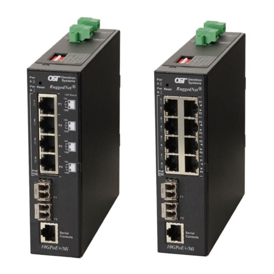
RuggedNet
10GPoE+/Mi
®
Managed 6 and 10 Port
PoE/PoE+ 10Gigabit Ethernet Switch
Quick Start Guide
38 Tesla, Irvine, CA 92618 USA
Phone: (949) 250-6510; Fax: (949) 250-6514
General and Copyright Notice
This publication is protected by U.S. and international copyright laws. All rights
reserved. The whole or any part of this publication may not be reproduced, stored
in a retrieval system, translated, transcribed, or transmitted, in any form, or by
any means, manual, electric, electronic, electromagnetic, mechanical, chemical,
optical or otherwise, without prior explicit written permission of Omnitron Systems
Technology, Inc.
The following trademarks are owned by Omnitron Systems Technology, Inc.:
FlexPoint
, FlexSwitch
, iConverter
TM
TM
OmniConverter
, RuggedNet
, Omnitron Systems Technology, Inc.
®
®
the Omnitron logo.
All other company or product names may be trademarks of their respective owners.
The information contained in this publication is subject to change without notice.
Omnitron Systems Technology, Inc. is not responsible for any inadvertent errors.
Warranty
This product is warranted to the original purchaser (Buyer) against defects in
material and workmanship for a period of two (2) years from the date of shipment.
A five (5) year warranty may be obtained by the original purchaser by registering
this product at www.omnitron-systems.com/support within ninety (90) days from the
date of shipment. During the warranty period, Omnitron will, at its option, repair or
replace a product which is proven to be defective with the same product or with a
product with at least the same functionality.
For warranty service, the product must be sent to an Omnitron designated facility,
at Buyer's expense. Omnitron will pay the shipping charge to return the product
to Buyer's designated US address using Omnitron's standard shipping method.
Limitation of Warranty
The foregoing warranty shall not apply to product malfunctions resulting from
improper or inadequate use and/or maintenance of the equipment by Buyer, Buyer-
supplied equipment, Buyer-supplied interfacing, unauthorized modifications or
tampering with equipment (including removal of equipment cover by personnel not
specifically authorized and certified by Omnitron), or misuse, or operating outside
the environmental specification of the product (including but not limited to voltage,
ambient temperature, radiation, unusual dust, etc.), or improper site preparation
or maintenance.
No other warranty is expressed or implied. Omnitron specifically disclaims the implied
warranties of merchantability and fitness for any particular purpose.
The remedies provided herein are the Buyer's sole and exclusive remedies. Omnitron
shall not be liable for any direct, indirect, special, incidental, or consequential
damages, whether based on contract, tort, or any legal theory.
, miConverter
, NetOutlook
, OmniLight
®
TM
®
, OST
TM
Page 2
,
®
and
TM
Advertisement
Table of Contents

Related Manuals for Omnitron Systems RuggedNet 10GPoE+/Mi


Summary of Contents for Omnitron Systems RuggedNet 10GPoE+/Mi
- Page 1 Omnitron Systems Technology, Inc. The following trademarks are owned by Omnitron Systems Technology, Inc.:...
-
Page 2: Product Overview
Directive) of the European Community directive 2012/19/EU on waste electrical and electronic equipment (WEEE) which, together with the RoHS Directive 2015/863/ The RuggedNet 10GPoE+/Mi is a ruggedized managed PoE and PoE+ industrial EU, for electrical and electronic equipment sold in the EU after July 2019. Such... -
Page 3: Serial Console Port
1) Configure DIP-switches The DIP-switches are located on the top of the module. The DIP-switches are used to configure modes of operation, networking features and PoE reset. Front Panel Layout Serial Console Port To configure the module using the serial port, attach a DB-9 serial (RS-232) equipped computer with terminal emulation software such as Procomm or Putty to the serial port on the module using a RJ-45 to DB-9 serial cable (not included). -
Page 4: Switch Mode
Dual Device Mode Function When configured for Dual Device Mode, the module is configured as two logically LEFT LEFT Switch Mode (factory default) independent Layer 2 switches. On models with 4 RJ-45 user ports, Port F1 is LEFT RIGHT Directed Switch Mode associated with ports P1 and P2 and Port F2 is associated with ports P3 and P4. -
Page 5: Installing The Module
When configured for Uplink Redundant Mode “no return to primary”, the uplink When uplink redundancy is enabled, the loss of link on either F1 or F2 will not cause ports operate as redundant links. A fault on the primary Port F1, will cause a fail the PD to be re-initialized even though the PSE Reset is enabled. -
Page 6: Connect Cables
Top View with DC Power Connector WARNING: Only a DC power source that complies with safety extra low voltage (SELV) requirements can be Power Connections connected to the DC-input power supply. WARNING REGARDING EARTHING GROUND: This equipment shall be connected to the DC supply system earthing electrode conductor or to a bonding jumper from an earthing terminal bar or bus to which the DC supply system earthing electrode is connected. -
Page 7: Verify Operation
Connect an appropriate multimode or single-mode fiber cable to the fiber port RJ-45 User Ports on the front of the module. It is important to ensure that the transmit (TX) is LED Indicators attached to the receive side of the transceiver at the other end and the receive Legend Indicator Description... -
Page 8: Specifications
Phone: (949) 250-6510 Cable Types Single-mode: 9/125µm Fax: (949) 250-6514 Serial: Category 3 and higher Address: Omnitron Systems Technology, Inc. 4 RJ-45 Ports: 8 RJ-45 Ports +46 to +57VDC; inclusive of +46 to +57VDC; inclusive of 38 Tesla tolerances tolerances...
Need help?
Do you have a question about the RuggedNet 10GPoE+/Mi and is the answer not in the manual?
Questions and answers