Advertisement
Quick Links
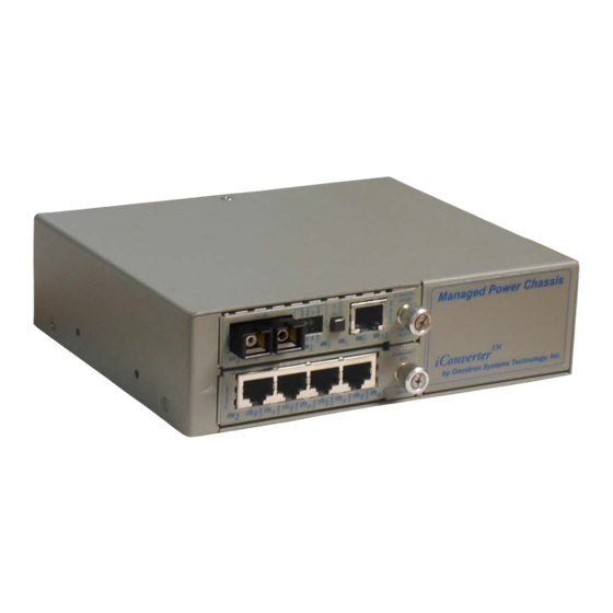
FlexSwitch
1Fx+4U Model 6550-FK Replacement Kit
TM
PRODUCT OVERVIEW
The 6550-FK is the direct replacement for the discontinued FlexSwitch Model 600XC 1Fx + 4U.
The 6550-FK replacement kit consists of one iConverter 10/100BASE-Tx to 100BASE-Fx
Media Converter Module and one iConverter 4Tx Switch Module installed in a iConverter
2-Module Chassis.
The 6550-FK provides auto-negotiating 10/100 RJ-45 ports with auto-crossover that enables
easy attachment to hubs, switches and workstations. The 100BASE-Fx fiber port supports
half or full duplex operation.
The 6550-FK features on-board and front panel accessible DIP-Switches for manual
configuration of the ports.
Chassis Models
FlexSwitch Replacement Matrix
Disconnected
Connector Type
Part
SC
6550-0
6550-0-FK
6550-2
6550-2-FK
6550-3
6550-3-FK
6551-0
-
6551-2
-
INSTALLATION PROCEDURE
1) Configure DIP-Switches
2) Install Module in Chassis and Connect Cables
3) Installing the Chassis
4) Apply AC Power
5) Verify Operation
User Manual
Replacement Part
Fiber Type
ST
-
MM
-
SM
-
SM
6551-0-FK
MM
6551-2-FK
SM
Page 1
1) Configure DIP-Switches
The 6550-FK has been pre-configured with Auto-Negotiation enabled on all RJ-45 ports for
plug and play easy of use. However, the iConverter Modules offer additional configuration
flexibility.
4 Port Switch Module
Each 4-Port Switch Module has been pre-configured for Auto-Negotiation with Backplane
A and B Enabled.
Backplane Port A Enable/Disable
This DIP-Switch must be in the LEFT "Enable" position for the module to operate correctly.
The switch provides backplane connectivity with the other switch module.
Backplane Port B Enable/Disable
This DIP-Switch must be in the LEFT "Enable" position for the module to operate correctly.
The switch provides backplane connectivity with the other switch module.
Port 1 and Port 2 RJ-45 Auto-Negotiate/Manual
When this DIP-Switch is in the RIGHT "AN" position, the Port automatically determines the
Distance
speed and duplex mode of the connecting copper device. If the connecting device cannot
provide the proper signal to indicate its own mode of operation, this DIP-Switch should be
5km
set to the LEFT "Man" position. Manual mode requires manually configuring the RJ-45 port
to match the speed and the duplex mode of the connecting device using the Speed and
30km
Duplex DIP-Switches.
60km
When a port is configured for Auto-Negotiation, the automatic crossover detection is enabled
5km
for that particular port. Automatic crossover detection is disabled when the port is configured
30km
for manual negotiation.
Port 1 and Port 2 Speed 10/100Mbps
When the port is configured for Manual Mode (SW3/SW6 in the LEFT position), the Speed
DIP-Switch determines the speed of operation for the designated port. Setting the Speed
DIP-Switch to the RIGHT "100" position forces the port to operate at 100Mbps. Setting this
DIP-Switch to LEFT "10" position forces the port to operate at 10Mbps. Adjust the Speed
DIP-Switch to match the speed of the connecting device.
Port 1 and Port 2 Duplex Full/Half-Duplex
When the port is configured for Manual Mode (SW3/SW6 in the LEFT position), the Duplex
DIP-Switch determines the duplex operation mode for the port. Setting the Duplex DIP-
Switch to the RIGHT "FD" position forces the port to operate in Full-Duplex. Setting this
4 Port Switch Module Default DIP-Switch Settings
Page 2
Advertisement

Related Manuals for Omnitron Systems FlexSwitch 6550-FK


Summary of Contents for Omnitron Systems FlexSwitch 6550-FK
- Page 1 1) Configure DIP-Switches The 6550-FK has been pre-configured with Auto-Negotiation enabled on all RJ-45 ports for plug and play easy of use. However, the iConverter Modules offer additional configuration flexibility. FlexSwitch 1Fx+4U Model 6550-FK Replacement Kit 4 Port Switch Module User Manual Each 4-Port Switch Module has been pre-configured for Auto-Negotiation with Backplane A and B Enabled.
- Page 2 The modules are pre-configured as illustrated below. DIP-Switch to the LEFT “HD” position forces the port to operate in Half-Duplex. Adjust the Duplex DIP-Switch to match duplex mode the connecting UTP device. Remote Fault Detect Enable When a port is configured for Auto-Negotiation, the Duplex DIP-Switch will determine if the port BPOEN Backplane Enable advertises Full-Duplex or Half-Duplex.
- Page 3 3) Installing the Chassis 5) LED Indicators Wall and Rack Mounting Each module has LED indicators to provide connection information. The 2-Module chassis can be wall/rack mounted by attaching the optional wall/rack mount 4 Port Switch Module brackets (8249-0). A 19” Rack Mount Shelf (8260-0) is available to install two 2-Module LED Function chassis.
- Page 4 All other company or product names may be trademarks of their respective owners. Phone: (949) 250-6510 The information contained in this publication is subject to change without notice. Omnitron Systems Technology, Inc. is not responsible for any inadvertent errors. Fax:...
Need help?
Do you have a question about the FlexSwitch 6550-FK and is the answer not in the manual?
Questions and answers