Table of Contents
Advertisement
Quick Links
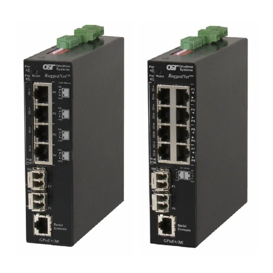
RuggedNet
®
Managed 6 and 10 Port
PoE/PoE+ Gigabit Ethernet Switch
Quick Start Guide
38 Tesla, Irvine, CA 92618 USA
Phone: (949) 250-6510; Fax: (949) 250-6514
GPoE+/Mi
General and Copyright Notice
This publication is protected by U.S. and international copyright laws. All rights
reserved. The whole or any part of this publication may not be reproduced, stored
in a retrieval system, translated, transcribed, or transmitted, in any form, or by
any means, manual, electric, electronic, electromagnetic, mechanical, chemical,
optical or otherwise, without prior explicit written permission of Omnitron Systems
Technology, Inc.
The following trademarks are owned by Omnitron Systems Technology, Inc.:
FlexPoint
, FlexSwitch
, iConverter
TM
TM
OmniConverter
, RuggedNet
, Omnitron Systems Technology, Inc.
®
®
the Omnitron logo.
All other company or product names may be trademarks of their respective owners.
The information contained in this publication is subject to change without notice.
Omnitron Systems Technology, Inc. is not responsible for any inadvertent errors.
Warranty
This product is warranted to the original purchaser (Buyer) against defects in
material and workmanship for a period of two (2) years from the date of shipment.
A five (5) year warranty may be obtained by the original purchaser by registering
this product at www.omnitron-systems.com/support within ninety (90) days from the
date of shipment. During the warranty period, Omnitron will, at its option, repair or
replace a product which is proven to be defective with the same product or with a
product with at least the same functionality.
For warranty service, the product must be sent to an Omnitron designated facility,
at Buyer's expense. Omnitron will pay the shipping charge to return the product
to Buyer's designated US address using Omnitron's standard shipping method.
Limitation of Warranty
The foregoing warranty shall not apply to product malfunctions resulting from
improper or inadequate use and/or maintenance of the equipment by Buyer, Buyer-
supplied equipment, Buyer-supplied interfacing, unauthorized modifications or
tampering with equipment (including removal of equipment cover by personnel not
specifically authorized and certified by Omnitron), or misuse, or operating outside
the environmental specification of the product (including but not limited to voltage,
ambient temperature, radiation, unusual dust, etc.), or improper site preparation
or maintenance.
No other warranty is expressed or implied. Omnitron specifically disclaims the implied
warranties of merchantability and fitness for any particular purpose.
The remedies provided herein are the Buyer's sole and exclusive remedies. Omnitron
shall not be liable for any direct, indirect, special, incidental, or consequential
damages, whether based on contract, tort, or any legal theory.
, miConverter
, NetOutlook
, OmniLight
®
TM
®
, OST
TM
Page 2
,
®
and
TM
Advertisement
Table of Contents

Related Manuals for Omnitron Systems RuggedNet GPoE+/Mi


Summary of Contents for Omnitron Systems RuggedNet GPoE+/Mi
- Page 1 Omnitron Systems Technology, Inc. The following trademarks are owned by Omnitron Systems Technology, Inc.:...
-
Page 2: Product Overview
Directive) of the European Community directive 2012/19/EU on waste electrical and electronic equipment (WEEE) which, together with the RoHS Directive 2015/863/ The RuggedNet GPoE+/Mi is a ruggedized managed PoE and PoE+ industrial EU, for electrical and electronic equipment sold in the EU after July 2019. Such... -
Page 3: Installation Procedure
3) Apply DC Power 4) Connect Cables 5) Verify Operation 1) Configure DIP-switches DIP-switches are located on the side of the RuggedNet GPoE+/Mi. The DIP-switches are used to configure modes of operation, networking features and PoE reset. Front Panel Layout Serial Console Port... -
Page 4: Switch Mode
Function LEFT LEFT Switch Mode (factory default) LEFT RIGHT Directed Switch Mode RIGHT LEFT Dual Device Mode - Switch Mode RIGHT RIGHT Dual Device Mode - Directed Switch Mode Modes of Operation Switch Mode When configured for Switch Mode (factory default), the module operates as a standard layer 2 switch. - Page 5 Dual Device Mode Redundant Uplink When configured for Uplink Redundant Mode “return to primary’, a fault on the When models with 4 RJ-45 user ports are configured for Dual Device Mode and Directed Switch Mode, the traffic from ports P1 and P2 is only forwarded to uplink primary Port F1, will cause a fail over to the secondary Port F2 within 50msec.
-
Page 6: Installing The Module
ports, ports P1 and P2 will drop PoE power when a loss of receive link on F1 is WARNING: Only a DC power source that complies with detected and ports P3 and P4 will drop PoE power when a loss of receive link on safety extra low voltage (SELV) requirements can be F2 is detected. -
Page 7: Connect Cables
4) Connect Cables When using SFP models, insert the SFP fiber transceiver into the SFP receptacle on the front of the module (see the SFP Data Sheet 091-17000-001 for supported Gigabit transceivers). NOTE: The release latch of the SFP fiber transceiver must be in the closed (up) position before insertion. -
Page 8: Verify Operation
5) Verify Operation RJ-45 PoE User Ports LED Indicators Verify the module is operational by viewing the LED indicators. Legend Indicator Description Power No link LED Indicators Green - ON Port linked at 100Mbps Legend Indicator Description Green - Blinking at 10Hz Port data activity at 100Mbps Unit not powered Amber -ON... -
Page 9: Specifications
Specifications Safety: UL 60950-1, UL-62368-1, IEC 60950-1:2005+A1:2009, RuggedNet ® GPoE+/Mi IEC 62368:2014/A11:2017, Description 10/100/1000BASE-T with Gigabit Fiber or Copper Uplinks EN 60950-1:2006+A11:2009+A1:2010+A12:2011 Ruggedized Managed PoE+ Ethernet Switch +A2:2013, CAN/CSA C22.2 No. 60950-1, IEEE 802.3, CAN/CSA C22.2 No. 62368-1-14, IEEE 802.1Q, CE Mark IEEE 802.1ad, EMC:... -
Page 10: Customer Support Information
Customer Support Information If you encounter problems while installing this product, contact Omnitron Technical Support: Phone: (949) 250-6510 Fax: (949) 250-6514 Address: Omnitron Systems Technology, Inc. 38 Tesla Irvine, CA 92618, USA Email: support@omnitron-systems.com URL: www.omnitron-systems.com Intentionally Left Blank 040-09540-001C...
Need help?
Do you have a question about the RuggedNet GPoE+/Mi and is the answer not in the manual?
Questions and answers