Table of Contents
Advertisement
WS-2801A Advanced Color Wireless
Weather Station User Manual
Table of Contents
1 Introduction ..................................................................3
1.1 What's New with the WS-2801A ..........................4
1.2 Features .................................................................4
2 Quick Start Guide .........................................................5
3 Getting Started ..............................................................5
3.1 Parts List ................................................................6
3.2 Recommend Tools .................................................7
3.3 Thermo-Hygrometer Sensor Set Up ......................7
3.4 Display Console ..................................................10
3.4.1 Display Console Layout ...............................10
3.4.2 Display Console Set Up................................12
3.4.3 Display Console Set Up................................13
3.5 Sensor Operation Verification .............................16
3.6 Sensor Placement ................................................17
4 Console Operation ......................................................20
4.1 Set Mode .............................................................20
Version 2.7.1 ©Copyright 2019, Ambient LLC. All Rights Reserved.
Page 1
Advertisement
Table of Contents

Related Manuals for Ambient Weather WS-2801A


Summary of Contents for Ambient Weather WS-2801A
-
Page 1: Table Of Contents
WS-2801A Advanced Color Wireless Weather Station User Manual Table of Contents 1 Introduction ..............3 1.1 What’s New with the WS-2801A ......4 1.2 Features ..............4 2 Quick Start Guide ............5 3 Getting Started ..............5 3.1 Parts List ..............6 3.2 Recommend Tools ..........7 3.3 Thermo-Hygrometer Sensor Set Up ......7... - Page 2 4.1.1 Time Zones ...........24 4.2 Barometric Pressure ..........25 4.2.1 Barometric Pressure History ......25 4.2.2 Relative Pressure Calibration .......26 4.2.3 Relative vs. Absolute Pressure .....26 4.3 Dew Point ............27 4.4 Multiple Channel Selection and Scroll Mode ..27 4.5 Alarms ..............28 4.5.1 View Alarm Time .........28 4.5.2 Time Alarm Settings Mode ......28 4.5.3 Cancelling the Alarm ........29 4.5.4 Low Temperature Alarm .......30...
-
Page 3: Introduction
9 Liability Disclaimer ............49 10 FCC Statement ............50 11 Warranty Information ..........51 1 Introduction Thank you for your purchase of the Ambient Weather WS-2801A Wireless Color Weather Station. The following user guide provides step by step instructions for installation, operation and troubleshooting. To... -
Page 4: What's New With The Ws-2801A
1.1 What’s New with the WS-2801A The WS-2801 only supported one remote wireless sensor. The WS-2801A supports up to three wireless remote sensors. The WS-2801A adds scroll mode, which allows you to view all three channels without pressing any buttons. 1.2 Features The WS-2801A features: ... -
Page 5: Quick Start Guide
Install Sensor Calibrate Barometer 4.2 and 3 Getting Started The WS-2801A weather station consists of a display console (receiver), thermos-hygrometer sensor and AC adapter. Note: The power up sequence must be performed in the order shown in this section (remote transmitter first, display console second) to properly synchronize the remote sensor to the console. -
Page 6: Parts List
3.1 Parts List Item Image Display Console (WS-2801A-C) Frame Dimensions (LxHxW): 6.36 x 3.39 x 0.86” (161.5 x 86 x 21.5 mm) Thermo-hygrometer transmitter (WH32M) Dimensions (LxHxW): 4.80 x 1.57 x 0.71” (122 x 40 x 18 mm) Manual Power Adapter Figure 1 Version 2.7.1 ©Copyright 2019, Ambient LLC. -
Page 7: Recommend Tools
3.2 Recommend Tools Hammer and nail for hanging remote thermo-hygrometer transmitter. 3.3 Thermo-Hygrometer Sensor Set Up Remove the battery door on the back of the sensor, as shown in Figure 2. Figure 2 Version 2.7.1 ©Copyright 2019, Ambient LLC. All Rights Reserved. Page 7... - Page 8 1. BEFORE inserting the batteries, switch the channel switch to the appropriate channel. If you have one sensor, set the switch to Channel 1. If you have two sensors, set the second sensor to Channel 2. If you own three sensors, set the third sensor to Channel 3.
- Page 9 Note: We recommend lithium batteries for cold weather climates, but alkaline batteries are sufficient for most climates. We do not recommend rechargeable batteries. They have lower voltages, do not operate well at wide temperature ranges, and do not last as long, resulting in poorer reception. Note: If the incorrect channel number is selected, change the channel number switch on the back of the sensor, and remove and reinsert the batteries for...
-
Page 10: Display Console
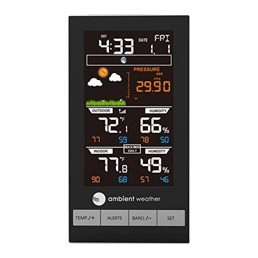
3.4 Display Console 3.4.1 Display Console Layout The display console layout is shown in Figure 4. Figure 4 Version 2.7.1 ©Copyright 2019, Ambient LLC. All Rights Reserved. Page 10... - Page 11 1. Daylight Savings Time 14. Outdoor humidity 2. Radio controlled 15. Outdoor humidity reception 3. Time 16. Min indoor humidity 4. Week day 17. Max indoor humidity 5. Date 18. Min indoor temperature 6. Moon phase 19. Max indoor temperature 7.
-
Page 12: Display Console Set Up
3.4.2 Display Console Set Up Version 2.7.1 ©Copyright 2019, Ambient LLC. All Rights Reserved. Page 12... -
Page 13: Display Console Set Up
Figure 5 3.4.3 Display Console Set Up Place the remote thermo-hygrometer about 5 to 10 feet away from the display console (if the sensor is too close, it may not be received by the display console). 1. Insert the power adapter into the power jack of the console, and plug in the adapter. - Page 14 adapter. 2. Remove the battery door on the back of the display. Insert three AAA (alkaline or lithium, avoid rechargeable) batteries in the back of the display console. Looking at the back of the unit (left to right), the polarity is (-) (+) for the top battery, (+) (-) for the middle battery and (-) (+) for the bottom battery.
- Page 15 phase, date and time. The remote search icon will turn on: Do not touch any buttons until the remote sensor reports in, otherwise the remote sensor search mode will be terminated and the search icon will turn off. When the remote sensor data has been received, the console will automatically switch to the normal mode, and all further settings can be performed.
-
Page 16: Sensor Operation Verification
If the signal reception is not successful (normally during the day due to solar interference), the sensor search will be cancelled, the outdoor temperature and humidity will update as normal, and the RCC search will automatically resume every two hours until the signal is successfully captured. -
Page 17: Sensor Placement
3.6 Sensor Placement It is recommended you mount the remote sensor outside on a north facing wall, in a shaded area, at a height at or above the receiver. If a north facing wall is not possible, choose a shaded area, under an eve. Direct sunlight and radiant heat sources will result in inaccurate temperature readings. -
Page 18: Best Practices For Wireless Communication
Figure 6 Figure 7 3.7 Best Practices Wireless Communication Wireless communication is susceptible to interference, distance, walls and metal barriers. We recommend the following best practices for trouble free wireless communication. 1. Electro-Magnetic Interference (EMI). Keep the Version 2.7.1 ©Copyright 2019, Ambient LLC. All Rights Reserved. Page 18... - Page 19 console several feet away from computer monitors and TVs. 2. Radio Frequency Interference (RFI). If you have other 915 MHz devices and communication is intermittent, try turning off these other devices for troubleshooting purposes. You may need to relocate the transmitters or receivers to avoid intermittent communication.
-
Page 20: Console Operation
Brick 10-40% Concrete 40-80% Metal 90-100% 4 Console Operation Note: The console has four keys for easy operation: TEMP/+ key, ALARM key, BARO/- key and SET/CH/CH key. There are four program modes: Set Mode, Alarm Mode, Calibration Mode and Min/Max Mode. - Page 21 Command Function Description Settings SET/CH + BEEP Turns on or off Press TEMP/+ or 2 seconds the beep with BARO/- to each keystroke toggle OFF and SET/CH Reset max/min Press TEMP/+ or daily at 12:00am BARO/- to (on) or manually toggle OFF and (off) SET/CH...
- Page 22 SET/CH Minute of Day Press TEMP/+ to increase. BARO/- to decrease SET/CH Month Day Press TEMP/+ or Format BARO/- to toggle between M-D (month/day) format and D-M (day/month) format SET/CH Year Press TEMP/+ to increase and BARO/- to decrease SET/CH Month of Year Press TEMP/+ to increase and...
- Page 23 SET/CH PRESSU Relative Press TEMP/+ to RE REL Pressure increase. Calibration BARO/- to decrease. For details on relative barometric pressure calibration, reference Section 4.2.2. SET/CH Northern Press TEMP/+ to Hemisphere toggle between (NTH) or Northern and southern southern Hemisphere Hemisphere (STH) select SET/CH Exit Set Mode...
-
Page 24: Time Zones
4.1.1 Time Zones Hours Time Zone Cities from IDLW: International Date Line West NT: Nome Nome, AK AHST: Alaska-Hawaii Honolulu, HI Standard CAT: Central Alaska HST: Hawaii Standard YST: Yukon Standard Yukon Territory PST: Pacific Standard Los Angeles, CA, MST: Mountain Standard Denver, CO, USA CST: Central Standard Chicago, IL, USA... -
Page 25: Barometric Pressure
Hours Time Zone Cities from Astana Bangkok CCT: China Coast Bejing JST: Japan Standard Tokyo GST: Guam Standard Sydney Magadan IDLE: International Date Wellington, New Line East Zealand NZST: New Zealand Standard Figure 9 4.2 Barometric Pressure 4.2.1 Barometric Pressure History While in normal mode, press BARO/- to check the barometric pressure history. -
Page 26: Relative Pressure Calibration
4.2.2 Relative Pressure Calibration You will want to calculate your barometric pressure to an official reporting station in your area. Since barometric pressure does not drastically change in a 50 mile radius (unless the weather is rapidly changing), this method of calibration is acceptable. -
Page 27: Dew Point
The standard sea-level pressure is 29.92 in Hg (1013 mb). This is the average sea-level pressure around the world. Relative pressure measurements greater than 29.92 inHg (1013 mb) are considered high pressure and relative pressure measurements less than 29.92 inHg are considered low pressure. -
Page 28: Alarms
and the scroll icon will be displayed next to the channel number, and will scroll every 5 seconds. 4.5 Alarms 4.5.1 View Alarm Time While in normal mode, press the ALARM key to view the alarm time. The alarm icon will be displayed in the time field. -
Page 29: Cancelling The Alarm
Command Function Description Settings ALARM + 2 Alarm Set the Alarm Press TEMP/+ or seconds Hour Hour Time BARO/- to increase or decrease the alarm hour. SET/CH Alarm Set the Alarm Press TEMP/+ or Minute Hour Minute BARO/- to increase or decrease the alarm minute. -
Page 30: Low Temperature Alarm
4.5.4 Low Temperature Alarm The low temperature alarm sounds when the outdoor is between -3 °C and +2 °C (26.6 °F and 35.6 °F). The LO temperature icon will appear and flash on the console. If the BEEP is switched on, an audible alert will also activated when the low temperature alert occurs. - Page 31 the display). Enter the calibration offset to match the calibration source. Command Function Description Settings SET/CH CH 1 TEMP Calibrate the Press TEMP/+ or channel 1 BARO/- to BARO/- + temperature increase or 5 seconds decrease the outdoor temperature offset. SET/CH CH 1 Calibrate the...
- Page 32 temperature increase or decrease the outdoor temperature offset. SET/CH CH 3 Calibrate the Press TEMP/+ or HUMIDITY channel 3 BARO/- to humidity increase or decrease the outdoor humidity offset. SET/CH INDOOR Calibrate the Press TEMP/+ or TEMP indoor BARO/- to temperature increase or decrease the indoor...
-
Page 33: Max/Min Mode
or actual temperature is 60.0 °F. The uncalibrated or measured temperature is 58.7 °F. Offset = Calibrated Temperature – Uncalibrated Temperature = 60.0 – 58.7 = 1.3 °F. Enter the temperature offset +1.3 °F. Example 2: The calibrated absolute pressure from a calibrated pressure sensor, or actual absolute pressure is 28.61 inHg. - Page 34 Note: The calibration offset range limits are as follows: Temperature: ± 9°F Humidity: ± 9% Absolute: ± 50hpa (± 1.47 inHg) 4.7 Max/Min Mode The Max/Min data is displayed below each parameter. The orange parameter on the left is the maximum value since the last reset, and the blue parameter on the left is the minimum value since the last reset.
-
Page 35: Other Console Features
midnight. The MAX/MIN DAILY icon will be displayed. To switch this feature off, reference Section 4.1. 4.8 Other Console Features 4.8.1 Display Brightness Press the LIGHT/SNOOZE button to toggle the screen brightness between HIGH, MEDIUM and LOW. 4.8.2 Weather Forecasting The five weather icons are Sunny, Partly Cloudy, Cloudy, Rainy and Stormy. -
Page 36: Weather Forecasting Description And Limitations
Sunny Partly Cloudy Cloudy Pressure increses for Pressure increases Pressure decreases a sustained period of slightly, or initial slightly time power up Rainy Stormy Pressure decreases Pressure rapidly for a sustained period decreases of time Figure 14 4.8.3 Weather Forecasting Description and Limitations In general, if the rate of change of pressure increases, the weather is generally improving (sunny to partly cloudy). -
Page 37: Moon Phase
The reason the current conditions do not match the forecast icon is because the forecast is a prediction 24-48 hours in advance. In most locations, this prediction is only 70% accurate and it is a good idea to consult the National Weather Service for more accurate weather forecasts. - Page 38 Waxing First Waxing Full Crescent Quarter Gibbous Waning Third Waning Gibbous Quarter Southern Hemisphere: Waxing First Waxing Full Crescent Quarter Gibbous Waning Third Waning Gibbous Quarter Figure 15 Version 2.7.1 ©Copyright 2019, Ambient LLC. All Rights Reserved. Page 38...
-
Page 39: Pressure Tendency Arrows
4.8.5 Pressure Tendency Arrows The forecast trend arrow updates every 30 minutes. The trend reflects changes in pressure (1 hPa) over the past 3 hours. Pressure is rising Pressure is Pressure is falling unchanged Figure 16 4.8.6 Rate of Change of Pressure Graph The rate of change of pressure graphic is shown to the left of the barometric pressure and signifies the... -
Page 40: Resynchronizing Lost Sensor
Figure 17 4.8.7 Resynchronizing Lost Sensor If the signal is lost between the remote sensor (or transmitter) and the display console (or the receiver), to resynchronize, while in normal mode, Press and hold SET/CH and TEMP/+ button for 5 seconds, to register the outdoor transmitter. -
Page 41: Factory Reset
Please wait several minutes for the remote sensor reports in. Do not touch any buttons until synchronization is complete. If the synchronization fails, reset the console by removing one battery from the display console, disconnect from AC power, wait 10 seconds, and reinsert the battery and reconnect AC power. -
Page 42: Glossary Of Terms
Glossary of Terms Term Definition Accuracy Accuracy is defined as the ability of a measurement to match the actual value of the quantity being measured. Hygrometer A hygrometer is a device that measures relative humidity. Relative humidity is a term used to describe the amount or percentage of water vapor that exists in air. -
Page 43: Specifications
Relative Measured barometric pressure relative to Barometric your location or ambient Pressure conditions. HectoPascals Pressure units in SI (international system) (hPa) units of measurement. Same as millibars (1 hPa = 1 mbar) Inches of Pressure in Imperial units of measure. Mercury 1 inch of mercury = 33.86 millibars (inHg) -
Page 44: Measurement Specifications
6.2 Measurement Specifications The following table provides specifications for the measured parameters. Measurement Range Accuracy Resolution Indoor -14 to ± 1.8 °F 0.1 °F Temperature 140 °F ± 1 °C 0.1 °C -10 to 60 °C Outdoor -40 to ± 1.8 °F 0.1 °F Temperature 140 °F... -
Page 45: Power Consumption
6.3 Power Consumption Base station : 5V DC adaptor (included) 3xAAA 1.5V Batteries (not included) Remote sensor:2 x AA Batteries (not included) Battery life: About 12 months for base station About 12-24 months thermometer-hygrometer sensor (use lithium batteries in cold weather climates) 7 Troubleshooting Guide Problem... - Page 46 Problem Solution console. Make sure the remote sensor LCD display is working on both the console and the remote sensor. Install a fresh set of batteries in the remote thermo-hygrometer. For cold weather environments, install lithium batteries. Make sure the remote sensors are not transmitting through solid metal (acts as an RF shield), or earth barrier (down a hill).
- Page 47 Problem Solution Temperature Make sure the thermo-hygrometer is sensor reads too mounted in a shaded area. The pre high in the day preferred location is a north facing time. wall because it is in the shade most of the day. Consider the following radiation shield if this is not possible: http://www.ambientweather.com/am wesrpatean.html...
-
Page 48: Accessories
Description Energizer AAA Lithium AAA lithium batteries for Battery (2-pack) - cold weather climates. Batteries for Long Life and Cold Climates Ambient Weather Solar Radiation Shield SRS100LX improves temperature Temperature and accuracy for hot weather Humidity Solar climates. Install over Radiation Shield thermo-hygrometer. -
Page 49: Liability Disclaimer
Accessory Description Ambient Weather The WS-2801A supports up to WH32M Wireless three wireless remote sensors. Remote Sensors 9 Liability Disclaimer Please help in the preservation of the environment and return used batteries to an authorized depot. The electrical and electronic wastes contain hazardous substances. -
Page 50: Fcc Statement
children. No part of this manual may be reproduced without written authorization of the manufacturer. Ambient, LLC WILL NOT ASSUME LIABILITY FOR INCIDENTAL, CONSEQUENTIAL, PUNITIVE, OR OTHER SIMILAR DAMAGES ASSOCIATED WITH THE OPERATION OR MALFUNCTION OF THIS PRODUCT. 10 FCC Statement Statement according to FCC part 15.19: This device complies with part 15 of the FCC rules. -
Page 51: Warranty Information
equipment generates, uses and can radiate radio frequency energy and, if not installed and used in accordance with the instructions, may cause harmful interference to radio communications. However, there is no guarantee that interference will not occur in a particular installation. If this equipment does cause harmful interference to radio or television reception, which can be determined by turning the equipment off and on, the user is encouraged to try to... - Page 52 LLC for problem determination and service procedures. Warranty service can only be performed by a Ambient, LLC. The original dated bill of sale must be presented upon request as proof of purchase to Ambient, LLC. Your Ambient, LLC warranty covers all defects in material and workmanship with the following specified exceptions: (1) damage caused by accident, unreasonable use or neglect (lack of reasonable and necessary...
- Page 53 Version 2.7.1 ©Copyright 2019, Ambient LLC. All Rights Reserved. Page 53...
Need help?
Do you have a question about the WS-2801A and is the answer not in the manual?
Questions and answers