Table of Contents

Subscribe to Our Youtube Channel
Related Manuals for Ecoflam MAIOR P 700.1 PRE


Summary of Contents for Ecoflam MAIOR P 700.1 PRE
- Page 1 LIGHT OIL BURNERS MAIOR P 700.1 PRE MAIOR P 800.1 PRE MAIOR P 1000.1 PRE MAIOR P 1200.1 PRE Technical data Operating instructions Electric diagrams Spare parts list MAIOR P 700.1 PRE TC S 3146429 13-02-2019...
- Page 2 Servomotor Lamtec - Air damper motor pre-setting Adjusting the pump pressure Adjusting the intermediate burner capacity Maintenance program Troubleshooting instructions Operating troubles Appendix Control box - Display Fluidics nozzle chart Bergonzo nozzle tables Pump and pressure regulators Electrical diagrams Spare parts list www.ecoflamburners.com 420010985900...
-
Page 3: General Warnings Conformity Declaration
GENERAL WARNINGS CONFORMITY DECLARATION Important notes Use the accessories provided Declaration of conformity (flange, gasket, pins and nuts) to Ecoflam burners have been designed and for light oil burners install the burner onto the boiler, built in compliance with all current WARNING taking care not to damage the isolating regulations and directives. -
Page 4: Burner Designation
Additional accessories and options shall be installed by the installer in accordance to the instruction and local safety regulations and codes of practise. KITS Accessories Kits and accessories are managed and delivered separately. Component type Complete burner Kits Accessories www.ecoflamburners.com 420010985900... -
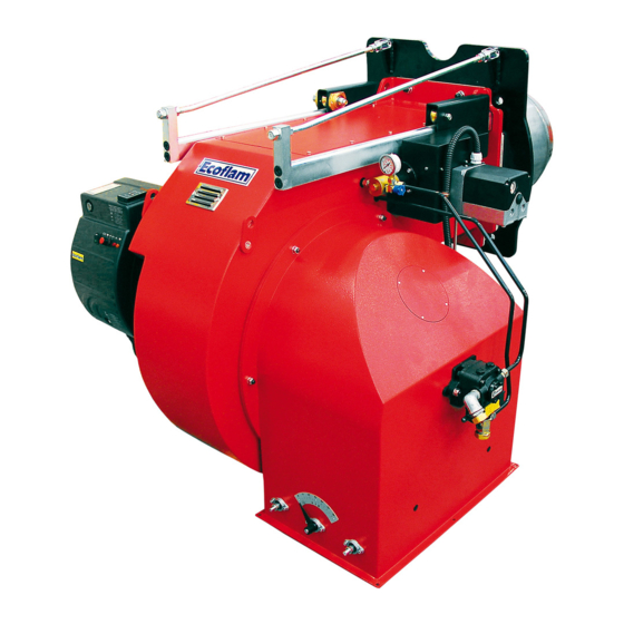
Page 5: Burner Description
6. Blast tube 8. Burner fixing flange 9. Air flap regulation 12. Lifting eyebolts 15. Servomotor 18. Oil pressure regulator Control panel A - reset key B - operating lamp D - ON/OFF switch E - display SA s.r 420010985900 www.ecoflamburners.com... -
Page 6: Technical Data
88,1 88,9 with silencer Ambient temperature storage -20°…+70° C Min/Ma Ambient temperature use -10°…+60° C Oil pump Model T5+TV T5+TV Oil pump motor 1,5 kW 1,5 kW 5,5 kW 5,5 kW Nozzles Type according to the output requested www.ecoflamburners.com 420010985900... - Page 7 11000 12000 13000 14000 15000 x 1000 adapt it to some special boiler 1000 2000 3000 4000 5000 6000 7000 8000 9000 10000 11000 12000 13000 14000 15000 16000 17000 kg/h 1000 1100 1200 1300 1400 or application. 420010985900 www.ecoflamburners.com...
-
Page 8: Overall Dimensions
OVERALL DIMENSIONS D - D1 600 mm SUNTEC D = Short head D1= Long head Dimensions (mm) Models MAIOR P 7-1200.1 Models MAIOR P 700.1 PRE 1255 1327 1270 MAIOR P 800.1 PRE 1500 1305 1270 MAIOR P 1000.1 PRE 1515... -
Page 9: Oil Operating Mode General Safety Functions
Any failure of the flame signal at the end of A voltage failure will result in a regular the safety period and a flame signal during shut-off of the burner. Upon voltage 420010985900 www.ecoflamburners.com... -
Page 10: Installation
3. Check the ignition electrodes and the nozzle on the burner head as per factory setting (see figures). The setting of the mixing and ignition unit according to the boiler output will be performed during commissioning procedure. 4. Check that the head is preset at 50%. www.ecoflamburners.com 420010985900... - Page 11 3. Bleed and pressure gauge port 4. Vacuum gauge port 5. Pressure adjustment 6. Nozzle outlet 7. Heater 8. Hose 9. Oil filter 10. Oil ball valve WARNING: Check that the pump rotation is correct and before start up it has been pre-filled 420010985900 www.ecoflamburners.com...
- Page 12 INSTALLATION commissioning it must be ensured that pump never run dry. NOZZLE SELECTION Please refer to diagram to select Ecoflam recommended nozzle for the output that is required given the output necessary in the installation. Intake from Tank Regular maintenance is highly recommended.
- Page 13 Adapters, multiple plugs and extension above 3 kW. cables may not be used for the For more information, please contact the equipment’s power supply. Ecoflam staff. An omnipolar switch in accordance with current safety regulations is required for the mains supply connection. ELECTRICAL CONNECTION...
-
Page 14: Checks Before Commissioning
Recording commissioning data WARNING Test n°1 n°2 n°3 n°4 Date Model Type oil Oil calorific value Burner output Burner output Flue gas temperature C° Air temperature C° Performance Corrective action Operator name Company www.ecoflamburners.com 420010985900... -
Page 15: Exhaust Gas Test
- and CO 2500 for heavy oil S (CO max = 15,60%) 2000 1500 = 21 CO max - CO gem = % 1000 gem = % CO measured on dry flue gases Fan capacity reduced by [%] 420010985900 www.ecoflamburners.com... -
Page 16: Main Switch
The optimal position depends on the output that we need to reach but the default setting shall be modified only when you are not able to reach the suggested combustion value by adjusting the air flow in the maximum flame. – www.ecoflamburners.com 420010985900... - Page 17 To increase the pressure turn clockwise, to decrease the pressure turn anticlockwise. 3. Tighten the nut B and pay attention not to turn also the adjusting screw. 4. Screw on the cap A, back to its previous position. 420010985900 www.ecoflamburners.com...
- Page 18 – pressure switch tap. LEGENDA 1. Oil pump VS. Oil safety valve 3. Adjusting cam 4. Check valve VL. Working valve PR. Pressostat (optional) 5. Nozzle 6. Pressure regulator 7. Manometer – pressure gauge www.ecoflamburners.com 420010985900...
-
Page 19: Maintenance Program
The exhaust gas loss can be calculated as follows: as follows: = exhaust gas temperature [°C] = combustion air temperature [°C] 0,37 0,49 = volumetric content of carbon = (195-22)( + 0,009) = 7,48% = (195-22)( + 0,007) = 7,83% dioxide [%] 10,8 12,8 420010985900 www.ecoflamburners.com... -
Page 20: Oil Filter Cleaning
Check the position of the 5÷6 mm electrodes after any intervention as wrong position could cause ignition troubles. OIL FILTER CLEANING ATTENTION: Periodically clean oil cartridge with gasoline and replace them if it is necessary! www.ecoflamburners.com 420010985900... -
Page 21: Troubleshooting Instructions
ENTER key to release Do not attempt to open or carry out repairs on the control unit. a fault interlocker.If the ENTER key is permanently lit red, a fault with Refer to LAMTEC manual attacched. an automatic restart is displayed. 420010985900 www.ecoflamburners.com... - Page 22 APPENDIX Fluidics nozzle chart www.ecoflamburners.com 420010985900...
- Page 23 APPENDIX Fluidics nozzle chart 420010985900 www.ecoflamburners.com...
- Page 24 APPENDIX Fluidics nozzle chart www.ecoflamburners.com 420010985900...
- Page 25 APPENDIX Bergonzo nozzle tables 420010985900 www.ecoflamburners.com...
- Page 26 APPENDIX Bergonzo nozzle tables www.ecoflamburners.com 420010985900...
- Page 27 APPENDIX Bergonzo nozzle tables 420010985900 www.ecoflamburners.com...
- Page 28 : 5 bars max. heavy oil : 5 bars max. Rated speed 3600 rpm max. Starting torque 0,3 N.m Choice of heater Cartridge Ø 12 mm Fitting according to DIN 40430, NFC 68190 (N°9 elec.) Rating 80-100 W www.ecoflamburners.com 420010985900...
- Page 29 Rated speed = 2850 rpm Starting torque 0,4 N.m Data shown are for new pumps, with no allowance for wear. Power consumption Choice of heater Cartridge Ø 12 mm Fitting according to DIN 40430, NFC 68190 (N°9 elec.) Rating 80-100 W 420010985900 www.ecoflamburners.com...
-
Page 30: Valve Identification
Remove cap-nut ➊ and washer ➋, unscrew lock-nut ➍. To increase pressure, turn adjusting screw ➌ clockwise. To decrease the pressure, turn screw anticlockwise. Block lock-nut ➍, refasten washer ➋ and cap-nut ➊. ➊ cap-nut ➋ adjusting screw ➌ washer ➍ ➎ ➍ lock-nut ➎ washer www.ecoflamburners.com 420010985900... - Page 31 APPENDIX Electrical diagrams 420010985900 www.ecoflamburners.com...
- Page 32 APPENDIX Electrical diagrams www.ecoflamburners.com 420010985900...
- Page 33 APPENDIX Spare parts 420010985900 www.ecoflamburners.com...
- Page 34 APPENDIX Spare parts list MAIOR P 700.1 PRE S N° DESCRIPTION code OIL PUMP SUNTEC TA5C30106 65322993 OIL VALVE AIR PRESSURE SWITCH LGW 3 A4 (0,4-3 MBAR) 65323039 COVER 65324059 GLASS 65320487 PEEP WINDOW FRAME 65320488 MOTOR 15 KW 65326334 GF560R ˜530 65325905...
- Page 35 420010985900 www.ecoflamburners.com...
- Page 36 Ecoflam Bruciatori S.p.A. reserves the right to make any adjustments, without prior notice, which is considered necessary or useful to its products, without affecting their main features Ecoflam Bruciatori S.p.A. si riserva il diritto di apportare ai prodotti le modifiche che riterrà necessarie o utili, senza pregiudicarne le caratteristiche principali.
Need help?
Do you have a question about the MAIOR P 700.1 PRE and is the answer not in the manual?
Questions and answers