
Related Manuals for Ecoflam MAIOR P 500-1 PRE


Summary of Contents for Ecoflam MAIOR P 500-1 PRE
- Page 1 LIGHT OIL BURNERS MAIOR P 500.1 PRE MAIOR P 600.1 PRE Technical data Operating instructions Electric diagrams Spare parts list MAIOR P 500 PRE.1 TC MAIOR P 500 PRE.1 TL S 3144806 10-01-2017...
-
Page 2: Table Of Contents
Servomotor Lamtec - Air damper motor pre-setting Adjusting the pump pressure Adjusting the intermediate burner capacity Maintenance program Troubleshooting instructions Operating troubles Appendix Control box - Display Fluidics nozzle chart Bergonzo nozzle tables Pump and pressure regulators Electrical diagrams Spare parts list 420010813300 www.ecoflam-burners.com... -
Page 3: General Warnings - Conformity Declaration
Ecoflam burners have been designed and built in compliance with all current regulations and directives. All burners comply to the safety and energy saving operation regulations within the standard of their respective performance range. - Page 4 Additional accessories and options shall be installed by the installer in accordance to the instruction and local safety regulations and codes of practise. KITS - Accessories Kits and accessories are managed and delivered separately. Component type Complete burner Kits Accessories 420010813300 www.ecoflam-burners.com...
-
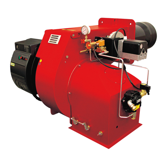
Page 5: Burner Description
BURNER DESCRIPTION Control panel main switch I/0 working lamp HLBT thermal lock-out lamp HLBT 0: OFF 1: ON 420010813300 www.ecoflam-burners.com... -
Page 6: Technical Data
IP55 Sound pressure level 91,1 92,8 dB(A) without silencer Sound pressure level tests 85,7 86,7 with silencer Ambient temperature storage -20°…+70° C Min/Max Ambient temperature use -10°…+60° C Oil pump Model Nozzles according to the output requested Type 420010813300 www.ecoflam-burners.com... -
Page 7: Working Diagrams
11000 12000 13000 14000 15000 x 1000 adapt it to some special boiler 1000 2000 3000 4000 5000 6000 7000 8000 9000 10000 11000 12000 13000 14000 15000 16000 17000 kg/h 1000 1100 1200 1300 1400 or application. 420010813300 www.ecoflam-burners.com... -
Page 8: Overall Dimensions
Make sure that between the boiler and the blast tube proper insulation is fitted. Packaging (only burner) Model MAIOR P 500.1 PRE S 1750 2380 1460 MAIOR P 600.1 PRE S 1750 2380 1460 420010813300 www.ecoflam-burners.com... -
Page 9: Oil Operating Mode - General Safety Functions
Any failure of the flame signal at the end of A voltage failure will result in a regular the safety period and a flame signal during shut-off of the burner. Upon voltage 420010813300 www.ecoflam-burners.com... -
Page 10: Installation
3. Check the ignition electrodes and the nozzle on the burner head as per factory setting (see figures). The setting of the mixing and ignition unit according to the boiler output will be performed during commissioning procedure. 4. Check that the head is preset at 50%. 420010813300 www.ecoflam-burners.com... -
Page 11: Oil Connection
3. Bleed and pressure gauge port 4. Vacuum gauge port 5. Pressure adjustment 6. Nozzle outlet 7. Heater 8. Hose 9. Oil filter 10. Oil ball valve WARNING: Check that the pump rotation is correct and before start up it has been pre-filled 420010813300 www.ecoflam-burners.com... -
Page 12: Feeding And Suction Line For Light Oil
INSTALLATION commissioning it must be ensured that pump never run dry. NOZZLE SELECTION Please refer to diagram to select Ecoflam recommended nozzle for the output that is required given the output necessary in the installation. Intake from Tank Regular maintenance is highly recommended. -
Page 13: Electrical Connections
3 kW. fig.1 400V to person and compromise the correct For more information, please contact the function of the burner therefore the Ecoflam staff. electrical system shall be checked by qualifed personnel. 230V The manufacturer declines all responsibility for modifcations or connections different from those shown in the electrical scheme. -
Page 14: Start-Up: Checking Procedure
• Check that control box is unlocked and in its original position. • A standard-compliant measuring point must be available, the exhaust gas duct up to the measuring point must be free of leaks to prevent anomalies in the measurement results. 420010813300 www.ecoflam-burners.com... -
Page 15: Exhaust Gas Test
- and CO 2500 for heavy oil S (CO max = 15,60%) 2000 1500 = 21 CO max - CO gem = % 1000 gem = % CO measured on dry flue gases Fan capacity reduced by [%] 420010813300 www.ecoflam-burners.com... -
Page 16: Start-Up Oil Side
The optimal position depends on the output that we need to reach but the default setting shall be modified only when you are not able to reach the suggested combustion value by adjusting the air flow in the maximum flame. – 420010813300 www.ecoflam-burners.com... -
Page 17: Servomotor Lamtec - Air Damper Motor Pre-Setting
Do never allow the pump working without oil for more than three minutes. NOTE: before starting the burner, check that the return pipe is open. An eventual obstruction could damage the pump sealing device. 420010813300 www.ecoflam-burners.com... -
Page 18: Adjusting The Intermediate Burner Capacity
– pressure switch tap. LEGENDA 1. Oil pump VS. Oil safety valve 3. Adjusting cam 4. Check valve VL. Working valve PR. Pressostat (optional) 5. Nozzle 6. Pressure regulator 7. Manometer – pressure gauge 420010813300 www.ecoflam-burners.com... -
Page 19: Maintenance Program
The exhaust gas loss can be calculated as follows: as follows: = exhaust gas temperature [°C] = combustion air temperature [°C] 0,37 0,49 = volumetric content of carbon = (195-22)( + 0,009) = 7,48% = (195-22)( + 0,007) = 7,83% dioxide [%] 10,8 12,8 420010813300 www.ecoflam-burners.com... - Page 20 Check the position of the 5÷6 mm electrodes after any intervention as wrong position could cause ignition troubles. OIL FILTER CLEANING ATTENTION: Periodically clean oil cartridge with gasoline and replace them if it is necessary! 420010813300 www.ecoflam-burners.com...
-
Page 21: Troubleshooting Instructions
Always switch off the power supply before installing or removing the control unit. Do not attempt to open Unlocks the control unit. or carry out repairs on the control unit. Red LED (flashes if a fault is present). Refer to LAMTEC manual attacched. 420010813300 www.ecoflam-burners.com... -
Page 22: Fluidics Nozzle Chart
Prior to burner start, check the nozzle size against the required output. It might be necessary to replace the nozzle (see nozzle selection diagram). ≤60 kg/h > 60 kg/h 80 100 % Output 420010813300 www.ecoflam-burners.com... -
Page 23: Bergonzo Nozzle Tables
APPENDIX Bergonzo nozzle tables 420010813300 www.ecoflam-burners.com... - Page 24 APPENDIX Bergonzo nozzle tables 420010813300 www.ecoflam-burners.com...
- Page 25 APPENDIX Bergonzo nozzle tables 420010813300 www.ecoflam-burners.com...
-
Page 26: Pump And Pressure Regulators
: 5 bars max. heavy oil : 5 bars max. Rated speed 3600 rpm max. Starting torque 0,3 N.m Choice of heater Cartridge Ø 12 mm Fitting according to DIN 40430, NFC 68190 (N°9 elec.) Rating 80-100 W 420010813300 www.ecoflam-burners.com... -
Page 27: Electrical Diagrams
APPENDIX Electrical diagrams 420010813300 www.ecoflam-burners.com... - Page 28 APPENDIX Electrical diagrams 420010813300 www.ecoflam-burners.com...
- Page 29 APPENDIX Spare parts 420010813300 www.ecoflam-burners.com...
-
Page 30: Spare Parts List
65323116 65323116 REMOTE CONTROL SWITCH AEG LS05.10 65323132 65323132 SILENCER 65074538 65074538 ADJUSTMENT PRESSURE 65324304 65324304 CHECK VALVE ART. FZVR1 65325066 65325066 MODULE FOR PROBE LCM100 LSB-M 667R0500-1 65311790 65311790 TC = SHORT HEAD TL = LONG HEAD 420010813300 www.ecoflam-burners.com... - Page 31 420010813300 www.ecoflam-burners.com...
- Page 32 Ecoflam Bruciatori S.p.A. reserves the right to make any adjustments, without prior notice, which is considered necessary or useful to its products, without affecting their main features Ecoflam Bruciatori S.p.A. si riserva il diritto di apportare ai prodotti le modifiche che riterrà necessarie o utili, senza pregiudicarne le caratteristiche principali.
Need help?
Do you have a question about the MAIOR P 500-1 PRE and is the answer not in the manual?
Questions and answers