Table of Contents
Advertisement
Quick Links
Instructions - Parts List
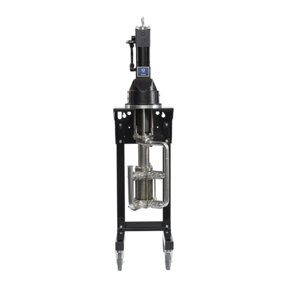
Viscount
Plus Pumps
Hydraulic-powered pumps for low pressure, high volume circulation of finishing materials.
Do not use for flushing or purging lines with caustics, acids, abrasive line strippers, and
other similar fluids. For professional use only.
Important Safety Instructions
Read all warnings and instructions in this
manual before using this equipment.
Save these instructions.
See Models, page 3, for model information.
See Technical Specifications, page 19, for maximum fluid
working pressure.
®
High-Flo
®
II 2 G
3A6939B
EN
Ex h IIB T3 Gb
Advertisement
Table of Contents

Related Manuals for Graco Viscount High-Flo Plus 25E933


Summary of Contents for Graco Viscount High-Flo Plus 25E933
- Page 1 Instructions - Parts List ® ® Viscount High-Flo Plus Pumps 3A6939B Hydraulic-powered pumps for low pressure, high volume circulation of finishing materials. Do not use for flushing or purging lines with caustics, acids, abrasive line strippers, and other similar fluids. For professional use only. Important Safety Instructions Read all warnings and instructions in this manual before using this equipment.
-
Page 2: Table Of Contents
Prime the Pump ......9 Graco Information ......20 Shutdown . -
Page 3: Models
Models Models Lower Lower Lower Connection Lower Cylinder Model No. Motor Size type Fittings Style Material Coating Coating 25E932 Viscount II 2500cc 17Z387 Sealed tri-clamp Ultralife™ Ultralife™ 25E933 Viscount II 3000cc 17Z388 Sealed tri-clamp Ultralife™ Ultralife™ 25E934 Viscount II 4000cc 17Z389 Sealed tri-clamp... -
Page 4: Warnings
Warnings Warnings The following warnings are for the setup, use, grounding, maintenance, and repair of this equipment. The exclama- tion point symbol alerts you to a general warning and the hazard symbols refer to procedure-specific risks. When these symbols appear in the body of this manual or on warning labels, refer back to these Warnings. Product-specific hazard symbols and warnings not covered in this section may appear throughout the body of this manual where applicable. - Page 5 Warnings EQUIPMENT MISUSE HAZARD Misuse can cause death or serious injury. • Do not operate the unit when fatigued or under the influence of drugs or alcohol. • Do not exceed the maximum working pressure or temperature rating of the lowest rated system com- ponent.
-
Page 6: Typical Installation
Typical Installation Typical Installation . 1 Typical Installation Key: Mix Tank Drain Line Pump Stand Pressure Reducing Valve Fluid Supply Line; 1-1/2 in. (38 mm) minimum diameter Hydraulic Supply Line Pressure Gauge Fluid Shutoff Valve Return Line Shutoff Valve Fluid Line; 1 in. (25 mm) minimum diameter Supply Line Shutoff Valve Surge Tank Flow Control Valve... -
Page 7: Installation
Installation Installation Grounding Object being sprayed: follow local code. Solvent pails used when flushing: follow local code. Use only conductive metal pails, placed on a grounded surface. Do not place the pail on a non-conductive sur- face, such as paper or cardboard, which interrupts The equipment must be grounded to reduce the risk grounding continuity. -
Page 8: Plumbing
Installation Plumbing Hydraulic Supply Line • Use a minimum 7/8 in. (22 mm) ID supply line (L). NOTICE The motor has a 1 in. (25.4 mm) npt(f) hydraulic oil To prevent a bellows failure: supply fitting. • Do not exceed fluid inlet pressure of 15 psi (0.1 •... -
Page 9: Operation
Operation Operation Pressure Relief Procedure Prime the Pump Follow the Pressure Relief Procedure when- NOTICE ever you see this symbol. Do not allow the pump to run quickly for a long period of time as this may damage the packings. NOTE: Sealed 4-ball lowers with bellows do not require Throat Seal Liquid (TSL). -
Page 10: Maintenance
Maintenance Maintenance Preventive Maintenance Performing a Stall Test Schedule Perform a stall test periodically to ensure the piston seal is in good working condition and to prevent system pres- The operating conditions of your particular system surization: determine how often maintenance is required. Establish a preventive maintenance schedule by recording when Close the fluid shutoff valve (D) closest to the pump on and what kind of maintenance is needed, and then... -
Page 11: Troubleshooting
Troubleshooting Troubleshooting Follow the Pressure Relief Procedure, page 9, before checking or servicing pump. Problem Cause Solution Pump output low on both strokes. Restricted hydraulic supply lines. Clear any obstructions; be sure all shutoff valves are open; increase pressure, but do not exceed maximum working pres- sure. -
Page 12: Repair
Repair Repair Disassembly Reassembly 1. If the coupling adapter (8) and tie rods (3) have not been disassembled from the motor (1), skip to step This equipment stays pressurized until pressure is If the coupling adapter (8) and tie rods (3) have manually relieved. - Page 13 Repair 6. Tighten the mounting plate screws. Torque the screws (13) to 50-55 ft-lb (68-75 N•m). 7. Insert the collars (6) into the coupling nut (5). Tighten the coupling nut onto the coupling adapter (8). Torque to 90-100 ft-lb (122-135 N•m) to allow the pump rod to align the lower on the tie rods.
-
Page 14: Parts
Parts Parts Viscount II Pump: Model 25Exxx with Sealed 4-Ball Plus Lower Parts List Ref. No. Part No. Description Qty. 223646 MOTOR, Viscount II, see detailed parts list in manual 308048 LOWER, Sealed 4-Ball Plus, see page 2 detailed parts list in manual 3A5348 16H434 TIE ROD, 10.80 in. -
Page 15: Dimensions
Dimensions Dimensions Viscount II Pump with Sealed 4-Ball Lower Approx. Weight Model Motor Lower Size Lower Type 25E932 VISCOUNT II 2500cc Sealed 57.2 1452 30.2 25E933 VISCOUNT II 3000cc Sealed 25E934 VISCOUNT II 4000cc Sealed 3A6939B... - Page 16 Dimensions Motor Mounting Hole Diagram Viscount II Motor Mounting Hole Layout 4X 3/8-16 UNC - 2B 7.43 in. (188 mm) 6.186 in. (157 mm) 7.43 in. 6.186 in. (157 mm) TI10465a 3A6939B...
-
Page 17: Performance Charts
Performance Charts Performance Charts To find Fluid Outlet Pressure (psi/MPa/bar) at a spe- To find Motor Hydraulic Oil Consumption (l/min. or cific fluid flow (lpm/gpm) and operating hydraulic pres- gpm) at a specific fluid flow (l/min. or gpm): sure (psi/MPa/bar): 1. - Page 18 Performance Charts See Models on page 3 for your pump part number. Viscount II Motor, 3000cc Lower CYCLES PER MIN. (27.6,2.76) (22.7) (24.1,2.41) (18.9) (20.7,2.07) (15.1) (17.2,1.72) (13.8,1.38) (11.4) (10.3,1.03) (7.6) (6.9,0.69) Key: (3.8) 10.3 MPa, 103 bar (1500 psi) (3.4,0.34) hydraulic pressure 7.2 MPa, 72.4 bar (1050 psi)
-
Page 19: Technical Specifications
Technical Specifications Technical Specifications Viscount II Motor with 2500, 3000, and 4000cc Pumps U.S. Metric Lower size 25E932 2500cc 25E933 3000cc 25E934 4000cc Maximum fluid working pressure 25E932 430 psi 3.0 MPa, 29.6 bar 25E933 360 psi 2.5 MPa, 24.8 bar 25E934 270 psi 1.9 MPa, 18.6 bar... -
Page 20: Graco Standard Warranty
With the exception of any special, extended, or limited warranty published by Graco, Graco will, for a period of twelve months from the date of sale, repair or replace any part of the equipment determined by Graco to be defective.
Need help?
Do you have a question about the Viscount High-Flo Plus 25E933 and is the answer not in the manual?
Questions and answers