Table of Contents
Advertisement
Quick Links
INSTRUCTIONS-PARTS LIST
Parts
INSTRUCTIONS
200 Liter (55 Gallon) Drum Size
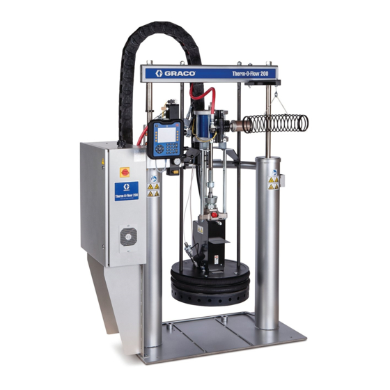
Hot Melt Drum Unloaders
All Models
Therm-O-Flow Plusr
Maximum Operating Temperature All Models 400_F (204_C)
Senator Powered Unloaders Models A–1 and A–2
Maximum Fluid Working Pressure 1900 psi
(13 MPa, 131 bar)
Maximum Air Inlet Pressure 100 psi (0.7 MPa, 7 bar)
Bulldog Powered Unloaders Models A–3 and A–4
Maximum Fluid Working Pressure 3100 psi
(21 MPa, 213 bar)
Maximum Air Inlet Pressure 100 psi (0.7 MPa, 7 bar)
King Powered Unloaders Models A–5 and A–6
Maximum Fluid Working Pressure 3900 psi
(26 MPa, 269 bar)
Maximum Air Inlet Pressure 90 psi (0.6 MPa, 6.2 bar)
Refer to page 2 for the Table of Contents.
Refer to Graco Form 309180, Installation and
Operation Guide for installation and operation
instructions.
This manual contains important
warnings and information.
READ AND KEEP FOR REFERENCE.
GRACO INC. P.O. BOX 1441
ECOPYRIGHT 2000, GRACO INC.
Graco Inc. is registered to I.S. EN ISO 9001
First choice when
quality counts.t
MINNEAPOLIS, MN 55440–1441
309085
Rev. A
TI0411
Advertisement
Table of Contents
Troubleshooting

Subscribe to Our Youtube Channel
Related Manuals for Graco Therm-O-Flow Plus HM55-D Series


Summary of Contents for Graco Therm-O-Flow Plus HM55-D Series
- Page 1 Refer to page 2 for the Table of Contents. Refer to Graco Form 309180, Installation and Operation Guide for installation and operation instructions. TI0411 GRACO INC. P.O. BOX 1441 MINNEAPOLIS, MN 55440–1441 ECOPYRIGHT 2000, GRACO INC. Graco Inc. is registered to I.S. EN ISO 9001...
-
Page 2: Table Of Contents
Junction Box Schematic ....Graco Factory P, I, and d Settings ... For 240 VAC Supply Units –... -
Page 3: Symbols
D Use the equipment only for its intended purpose. If you are uncertain about usage, call your Graco distributor. D Do not alter or modify this equipment. Use only genuine Graco parts and accessories. D Check the equipment daily. Repair or replace worn or damaged parts immediately. - Page 4 WARNING HOT SURFACE AND FLUID HAZARD Heated fluid can cause severe burns and can cause equipment surfaces to become very hot. D Wear eye protection, gloves and protective clothing when installing, operating, or servicing this dispensing system. D Be sure to tighten the bleed stick after bleeding the air. Otherwise hot material will leak out of the opening.
- Page 5 WARNING FIRE, EXPLOSION AND ELECTRIC SHOCK HAZARD Improper grounding, poor air ventilation, open flames, or sparks can cause a hazardous condition and result in fire, explosion, or electric shock and other serious injury. D Ground the equipment, the object being dispensed to, and all other electrically conductive objects in the dispense area.
- Page 6 WARNING TOXIC FLUID HAZARD Hazardous fluid or toxic fumes can cause serious injury or death if splashed in the eyes or on the skin, inhaled, or swallowed. D Know the specific hazards of the fluid you are using. D Store hazardous fluid in an approved container. Dispose of hazardous fluid according to all local, state and national guidelines.
-
Page 7: Overview
Overview How the Therm–O–Flow Plus Works D Heated Platen D Drum Ram A heated platen melts the sealant or adhesive and directs the molten material to the pump inlet. The D Heat Controls Supply Voltage material then travels through a heated Check–Mate D Heat Controls (number of heat zones) pump and heated fluid moves to the application tool. - Page 8 Typical Installation Master Air Valve (bleed-type) (required) 203 Air Line Lubricator Pump Air Supply Hose 204 Pump Air Regulator Electrical Control Panel 211 4-way Ram Valve (Ram Up/Ram Down) 102 Ram Module 214 Pump Bleed-Type Master Air Valve (required) 104 Heated Ram Plate Assembly 226 Main Air Line Inlet 106 Depressurization Valve 319 Ram Plate Bleed Stick...
-
Page 9: Typical Installation
Typical Installation System Accessories and Modules For operation and startup, refer to Graco form 309180, Therm–O–Flow Plus Installation and Operation Guide. Before you install the system you should be familiar The typical installation discussed below is only a guide with the parts discussed in the subsequent para- for selecting and installing system components and graphs. - Page 10 Typical Installation Heat Control Zone Selection The Therm–O–Flow Plus can be ordered withsix (code E–1) or eight (code E–2) heat zones (see Fig. 3). Zones 1 and 2 are always used for heated drum platen and the heated pump. Zones 3 and 4, 5 and 6, and optional zones 7 and 8 are each available as paired zones through a 16–pin connector.
- Page 11 Typical Installation Air Line Modules D Ram Air Supply Hose connects the ram air regula- tor to the air manifold. WARNING D Ram Plate Blow-off Valve controls the air pressure PRESSURIZED FLUID HAZARD AND to the ram plate blow-off. MOVING PARTS HAZARD The bleed-type master air valve (C) and D FRL (filter, regulator, lubricator) (202), (203), and auto depressurization valve (P) are re-...
-
Page 12: Installation
For information on connecting the hose and gun com- D setting controls on the electrical control panel ponents, follow the gun’s instructions. Graco form 309180, Therm–O–Flow Plus Installation Electrically connect the hoses to the electrical control and Operation Guide, includes: panel. -
Page 13: Ground The System
Installation Ground The System To reduce the risk of static sparking, ground the pump, object being dispensed to, and all other spraying/dis- pensing equipment used or located in the spraying/dis- Ground the supply unit as instructed here and in the pensing area. -
Page 14: Connecting The Electrical Control Panel To A Power Source
B–3 = Smooth bottom platen: 18 Kw For information about specific terminal locations and connections, see Control Panel Component Layout on page 74 and refer to Electrical Setup in Graco form 309180, Therm–O–Flow Plus Installation and Opera- tion Guide To connect the control panel to the electrical source: 1. -
Page 15: Check The Resistance Between The Supply Unit And The True Earth Ground
Installation Check the Resistance Between the Supply Sensor Resistance Checks Unit and the True Earth Ground WARNING ELECTROCUTION HAZARD WARNING To reduce risk of injury or damage to equipment, conduct these electrical FIRE, EXPLOSION, AND ELECTRIC checks with the main disconnect OFF. SHOCK HAZARD To reduce the risk of fire, explosion, or The package includes up to eight heat sensors and... - Page 16 Installation Heater Resistance Checks To check heater resistance: 1. Make sure the power is off and that the disconnect WARNING switch is in the OFF position. ELECTROCUTION HAZARD 2. Make electrical resistance checks for the compo- nents. Refer to Control Panel Component To reduce risk of injury or damage to Layout on page 74 for wiring diagram information.
-
Page 17: Overview Of The Temperature Controller Settings
Installation Overview of the Temperature Controller Settings Table 2. Graco Factory P, I, and d Settings The basic program settings for each temperature con- troller satisfy most application needs. These settings Category Unit Voltage are preset at the factory, but can be changed. The... -
Page 18: Flushing The System
Flush the system to avoid clean, and eliminate the factory-test oil from the contaminating the material that has been designated system. If necessary, check with Graco or the ma- for initial material loading. terial supplier for a recommended solvent. -
Page 19: Optional Low Level Kit 233096
Installation Optional Low Level Kit 233096 switch to the bracket as shown, with the limit switch lever in the center position of the bracket. This will The Low Level Kit is used to indicate that a drum is ensure it makes contact with the rod actuator. Place EMPTY or LOW, depending on the adjustment of the the rod actuator on the ram cylinder rod and adjust so limit switch. -
Page 20: Optional Inactivity Timer Kit 233097
Installation Optional Inactivity Timer Kit 233097 is 2.63 in. Refer to Fig. 7. Mount the collar over the existing connecting rod nut by breaking loose the The Inactivity Timer will shut off all power to the heat connection, running the air motor to allow the collar to zones when the pump has not operated for 2–10 fit over the nut, and reconnect the nut to the air motor hours. - Page 21 Installation Optional Inactivity Timer Kit 233097 (continued) Reserved location for Inactivity Timer (TR184) Selection E3. TI0549B Fig. 7 Control Box Wiring of T imer Relay A–1 to 1311 A–2 to 1092 1. Remove the terminal jumper between 1251 and 15 to 1251 1252.
- Page 22 Notes 309085...
-
Page 23: Operation
Start Up and Operation To relieve pressure in the supply unit, perform the following procedure: See Graco form 309180, Installation and Operation 1. Lock the gun/valve trigger safety. Guide, for detailed start up and operation instructions. 2. Shut off the main air supply to the pump. - Page 24 Operation Using the 7-Day Timer in the Optional Pendant WARNING Control Each Night: To reduce the risk of serious injury whenever you Follow this procedure when the 7-day timer is active: are instructed to relieve pressure, always follow the Pressure Relief Procedure (page 23). 1.
-
Page 25: Reading The Electrical Control Panel Indicators
Operation Reading the Electrical Control Panel Indicators Use the table and Fig. 9 below to read the indicators on the electrical control panel. Light Indicator: Indicator Meaning: Light is: Control On Power is on. Power is off. DIMLY LIT There may be a problem with the system power connections. Have connec- tions checked by a qualified electrician before attempting to start the sys- tem. -
Page 26: Reading The Temperature Controllers
Operation Reading the Temperature Controllers D turns off power to the heaters D lights the AUTO HEAT OFF light (AE) Refer to Form 309100 for instructions on reading the To re-heat the supply unit: CB100 temperature controller. Temperature Out of Range Should any of the temperatures go out of the preset range for any of the zones, power to the heated com- ponents is interrupted, and the HIGH TEMPERA-... -
Page 27: Resetting The Ground Fault Interrupt
Operation Resetting the Ground Fault Interrupt To reset the ground fault interrupt, have a qualified electrician: This control panel is equipped with a ground fault interrupt (GFPE) circuit breaker (Fig 11). If the discon- 1. Turn OFF the electrical disconnect on the electrical nect switch is ON, but all lights on the electrical control control panel. -
Page 28: Advanced Pendant Control Screen Map
Advanced Pendant Control Screen Map See Next Page TI0683 309085... - Page 29 Advanced Pendant Control Screen Map See Previous Page OP #1 OP #3 OP #4 LOADS LOADS DEFAULT DEFAULT SETTINGS SETTINGS FOR _F FOR _C TI0683 309085...
- Page 30 Notes 309085...
-
Page 31: Advanced Pendant Control
Advanced Pendant Control Refer to Fig. 12. The optional Advanced Pendant perature settings of each controller without the need to Control (Part No. 233098) is used for communicating manually access each temperature control. Three with the temperature controllers of a Therm-O-Flow recipes are available to help when you need to quickly Plus hot melt system. -
Page 32: Operation Of Pendant
The following functions are available in the SETUP screens. Reference the screen map on page 28. D Change Password (the Graco default from the factory is 11111111) The first line of the MAIN menu shows that this is the GRACO TOF+ PENDANT. TOF+ is an acronym for D Change the number of CONFIGURED zones on Therm-O-Flow Plus. - Page 33 Advanced Pendant Control Operation of Pendant (continued) To configure the zones properly in the pendant, pro- ceed to the SETUP selection, enter the correct pass- The first task to do when first using the Advanced word and CHG the Configured Zones. Pendant Control on a Therm-O-Flow Plus system is to G R A C O T O F +...
-
Page 34: Recipe Functions
Advanced Pendant Control Recipe Functions The SETBACK recipe is the first recipe shown. It shows the SV temperature zone #1 is 250_F. Viewing A recipe is a series of SV temperatures for all temper- the SV temperature for the remaining zones is done by ature zones on the system. - Page 35 Advanced Pendant Control Recipe Functions (continued) S E T B A C K To EDIT RECIPE SVs, access the SETUP manuals Z O N E and enter the correct password. S V : 2 5 0 F Z O N E ^ ^ P R V Z N + E X I T...
-
Page 36: Day Timer Functions
Advanced Pendant Control 7 Day Timer Functions Setup The 7 day timer works from a 24 hour clock. Shown below is an example of typical settings of the 7 day The 7 day timer is for starting and stopping of the heat time as viewed in the VIEW –... - Page 37 Advanced Pendant Control 7 Day Timer Functions (continued) To turn the Timer ON or OFF, return to the MAIN MENU and press the F2 (TR) key. The following To EDIT the 7 DAY TIMER SETTINGS, enter the screen will show. SETUP screens of the pendant by entering the correct password and pressing F5 (NEXT) until the following T I M E R...
-
Page 38: Date/Time Functions
Advanced Pendant Control Date/Time Functions 5 = C R O S S – O V E R C O N F I G On the MAIN menu the current DAY, DATE, and TIME is displayed. To edit the time and date, proceed to the 7 = 7 D A Y T I M E R... -
Page 39: Zone Setup/Pid Type Selection
> A C T I V E > E D I T < Z O N E # x x USED. If ACTIVE, the pendant must know what type of Graco heat device is connected so the proper PID N A M E : Z O N E... -
Page 40: Manual Send Sv Temperature
Advanced Pendant Control Manual Send SV Temperatures Here, the zones can be incremented up and down using the F1 (ZN–) and the F5(ZN+) keys. Pressing the F2 (SND) key will send the SV shown on the The pendant can be used to quickly change the SV of display to the zone shown. -
Page 41: Password Change
Enter the NEW PASSWORD, followed by the ENTER key. The password should be changed the first time the pendant is used. The Graco default password is 11111111 (eight 1s). Change the password, record the C O N F I R M... -
Page 42: Load Graco Defaults
This selection is not normally used when receiving a (F) will send all the settings to all the ACTIVE zones new system from Graco. This is used to setup all the with the proper settings for _F operation. Pressing F5... - Page 43 Notes 309085...
-
Page 44: Dual Ram Cross-Over Control Function
The unloaders are typically shipped pre-installed at the Graco factory with label (A) and (B) placed on the upper left hand corner of the NOTE: The 7 Day Timer settings take precedence main control box. - Page 45 Dual Ram Cross-Over Control Function C58011 Roller (2) Mount to Ram Piston Rod C58009 Bracket 241402 Switches (2) 243254 Auto Cross-Over Assembly (2) includes J–Box, light assy, and machine cables Only one Pendant To low switch mounted to either Unloader 116157 To empty switch To air motor solenoid (C07458)
-
Page 46: Setup Of X-Over
Dual Ram Cross-Over Control Function Setup of X-Over ATTENTION: Heated Header Assemblies should never be connected to zone #8 of an 8 Zone control panel. This zone is only rated for a maximum wattage There are 4 steps that must be completed before the of 250W. -
Page 47: Dedicate Zones
Dual Ram Cross-Over Control Function Dedicate Zones There are two options available in the Cross-Over Configuration screen. DEDICATE ZONES to a partic- ular unloader or FACTORY SETUP. FACTORY SET- To dedicate zones, access the SETUP screens by UP will be discussed later. Press A on the keypad to pressing F5 from the MAIN menu, enter the correct access the DEDICATE ZONES screen as shown password, acknowledge the proper zones are config-... -
Page 48: Starting/Stopping X-Over Operations
Dual Ram Cross-Over Control Function Starting/Stopping X-Over Operations As shown, the X-OVER screen will give the operator the prompt to change a drum. Pressing F1 will restart Shown below is the MAIN screen. This shows the 7 the heat zones of DRUM A, turn on the air solenoid DAY TIMER and the X-OVER are running. - Page 49 Dual Ram Cross-Over Control Function Starting/Stopping X-Over Operations NOTE: For systems that do not contain cross-over modules, the X-OVER screen will show the following. (continued) For changing DRUM B, the same sequence of screens is displayed as shown. X – O V E R N O T E N A B L E D E X I T...
-
Page 50: X-Over Factory Setup
Dual Ram Cross-Over Control Function X-Over Factory Setup To access this screen, from the MAIN screen, F5 (SETUP), enter the correct PASSWORD, acknowledge The FACTORY SETUP option within the X-OVER the correct zones are configured, proceed to the CONFIGURATION screen is typically available for CONFIGURE X-OVER selection, then press B. -
Page 51: Communication Errors
Communication Errors Contacts Available for Connection to If the pendant experiences communication errors, all communication to all devices is shut off and the pen- External Equipment dant will continue to display an error message and beep approximately every 5 sec until the operator A series of dry contacts are available for customer acknowledges the error. -
Page 52: Ram Troubleshooting
Ram Troubleshooting Problem Cause(s) Solution(s) Ram won’t raise or lower Closed main air valve or clogged air line Open air valve, clear air line Not enough air pressure Increase ram pressure Worn or damaged piston Replace piston. See procedure in Form 310523. -
Page 53: Heated Pump Troubleshooting
Heated Pump Troubleshooting For additional information about the Check-Mate 800 Displacement Pump, see Form 308570. Problem Cause(s) Solution(s) Rapid down stroke or up stroke Material not heated to proper Check and adjust temperature set point. (pump cavitation) pumping temperature. Wait for pump/plate to heat up. Air is trapped in pump. -
Page 54: Air Motor Troubleshooting
Air Motor Troubleshooting For additional information about the air motor, see manual 307049. Problem Cause(s) Solution(s) Air motor does not run Air motor solenoid is off Wait for heat zones in use to reach “window” around temperature set values. Air motor will not shift directions, Main air valve spool is dirty or damaged Clean/rebuild main air valve. -
Page 55: Service
Service Inspection Frequency 2. Using the ram hand valve lever on the air control (Fig. 14), move the ram to the DOWN position. Periodically (once a month), inspect the ram guide sleeves, rods and cylinders for wear or damage, replace all worn parts. See the Service section of Form 310523 for instructions on replacing worn parts. -
Page 56: Removing A Material Drum From The Supply Unit
Only remove the drum from the supply unit while the supply unit is hot. Observe the cautions and warnings, then follow steps 1 through 7 of the Drum Changing procedure in Graco form 309180, Installation and Op- eration Guide. Servicing the Ram Plate... - Page 57 1. If the material drum has already been removed from the supply unit, go to step 2. If you need to remove the material drum, perform steps 1 through 7 of the Drum Changing procedure in Graco form 309180, Installation and Operation Guide . 9520A Fig. 17 2.
-
Page 58: Pump Removal And Replacement
HEAT ON switch to OFF. remove the material drum, perform steps 1 through 7 of the Drum Changing procedure in Graco form 309180, Installation and Operation 9. Disconnect all material hoses. Guide. 10. Disconnect the pump from the junction box by: 2. -
Page 59: Separating The Pump Andthe Air Motor
Service Separating the Pump from the Air Motor Reattaching the Air Motor to the Pump Perform the above procedure in reverse order to To separate the pump from the air motor: reattach the pump to the air motor. Be sure that: NOTE: Refer to Parts information on page 64 while performing this procedure. -
Page 60: Junction Box Schematic
Service For 400, 480, and 575 VAC Supply Units – Junction Box Schematic TI0673 Fig. 18 309085... -
Page 61: For 240 Vac Supply Units - Junction Box Schematic
Service For 240 VAC Supply Units – Junction Box Schematic TI0673 Fig. 19 309085... -
Page 62: Parts
Parts All Models Supply Unit 11, 12 113, 114 15, 16 Hydraulic Powered Ram Models C–2 only. See Instruction form 310523 TI0411 309085... - Page 63 Parts All Models Supply Unit Part Part Description Description PUMP, See page 64 for model C14005 LABEL, heated equipment breakdown 101015 WASHER 233087 RAM, C–1 , air powered C19187 (See form 310523) 161822 BRACKET, mounting 918420 RAM, C–2 , oil powered 100672 SCREW (See form 310523)
-
Page 64: All Models Air Motor And Pump Assembly
Parts All Models Air Motor and Pump Assembly Part Description AIR MOTOR 217540 used on code A–1 see 307592 220571 used on code A–2 see 307592 208356 used on code A–3 see 307049 215255 used on code A–4 see 307304 207647 used on code A–5 see 306968 220106... - Page 65 Notes 309085...
-
Page 66: Model 243276 Series A Heated Pump
Parts Model 243276, Series A Heated Pump 618, 621, 622 TI0550 618, 621, 622 615, 616, 617 604, 632 Y612 Plate 613, 614 631Y 9519A 309085... - Page 67 Parts Model 243276, Series A Heated Pump Part Part Description Description 237795 PUMP, displacement, C20867 BUSHING, conduit; 3/4 npt Check-Matet 800; C20716 LOCKNUT, conduit; 3/4–14 see manual 308570 C20487 NIPPLE, hex; 3/4 npt 115654 HEATER, band, pump; 500 watt C32200 TERMINAL, ring;...
-
Page 68: Models 243300 & 243874 Ram Plate
Parts Part No. 243874 Ram Plate, Standard Grid (Code B –1) Part No. 243300 Ram Plate, Mega Flo (Code B –2) Part No. 243875 Ram Plate, Smooth Bottom (Code B –3) 335, 312, 311, 310, {320, 345 336,344 324, TI0544 { Use item 345 when replacing the gasket in item 320. - Page 69 Parts Part No. 243874 Ram Plate, Standard Grid (Code B –1) Part No. 243300 Ram Plate, Mega Flo (Code B –2) Part No. 243875 Ram Plate, Smooth Bottom (Code B –3) Part Part Description Description PLATE, ram 324 C19846 SCREW, cap, socket hd 617225 standard grid code B–1 325 517414...
-
Page 70: Model 243422 Depressurization Kit
Parts Part No. 243422 Depressurization Kit Part Part Description Description C07430 CONNECTOR, sealed C07403 NUT, wire; gray C20715 FITTING, conduit 617550 TERMINAL, ring; C07458 CONNECTOR, sealed 16–18 AWG x no. 6 bolt C20485 FITTING; 1/2 npt C32390 FILTER, breather 115712 VALVE, solenoid;... -
Page 71: Control Installation Kit
Parts Part No. 243302 6–Zone and 8–Zone Control Installation Kit Part Part Description Description 195865 FRAME, enclosure C32424 U-BOLT; 7 in. C19185 NUT, jam, hex 617727 STOP, control panel C19213 WASHER, lock C19802 SCREW, cap, socket hd C19200 WASHER, plain 110755 WASHER, plain C19124... -
Page 72: Model 243275 Drip Shield Mount Kit
Parts Part No. 243275 Drip Shield Mount Kit Part Part Description Description 195863 BRACKET 100133 WASHER, lock 617395 CLAMP, saddle 100101 SCREW, cap, hex head C32424 U-BOLT; 7 in. 115694 TRAY, drip shield 100131 NUT, hex 905, 906 904, 905 9615A 309085... -
Page 73: Model C32463 Saddle Assembly Clamp
Parts Option Code F-7 Part No. C32463 Saddle Assembly Clamp Part Part Description Description C32424 U-BOLT; 7 in. 100133 WASHER, lock 160111 CLAMP C38182 WASHER, plain 100103 PIN, cotter C32461 CLAMP, saddle 100307 NUT, hex 166265 PIN; not shown 804, 805 9617A 309085... -
Page 74: All Models Control Panel Component Layout
Parts All Models Control Panel Component Layout Contactors Power Hose & Guns Platen & Pump Solid State Connections Relay Pump Power Disconnect Heaters Solid State Relay for Platen Ground Fault Protector Solid State Relays Zones 3–8 Pump Fuses Power Leg Fuses 230V Transformer Fuses... -
Page 75: Control Box Spare Parts List
Check the control box number on your machine, then find that control box on the tables on this and the following pages. Refer to the illustration on page 74 for device numbers. Qty. in Device Manufacture Mfg # Graco # Panel 115969 6 Zone Control (230/240VAC) CR303 Potter–Brumfield KUIP–14D15–12 3PDT (VDE) (12VDC... - Page 76 Control Box Spare Parts List Qty. in Device Manufacture Mfg # Graco # Panel 115659 6 Zone Control (480VAC) CR303 Potter–Brumfield KUIP–14D15–12 3PDT (VDE) 116201 (12VDC Coil) CR125, 127, 129, 156, 168 Deltrol 20308–85 3PDT (SEMKO) 116202 (240VAC Coil) SSR222...
- Page 77 Control Box Spare Parts List Qty. in Device Manufacture Mfg # Graco # Panel 115973 8 Zone Control (230/240VAC) CR303 Potter–Brumfield KUIP–14D15–12 3PDT (VDE) 116201 (12VDC Coil) CR125, 127, 129, 156, 168 Deltrol 20308–85 3PDT (SEMKO) 116202 (240VAC Coil) SSR222...
- Page 78 Control Box Spare Parts List Qty. in Device Manufacture Mfg # Graco # Panel 115976 8 Zone Control (480VAC) CR303 Potter–Brumfield KUIP–14D15–12 3PDT (VDE) 116201 (12VDC Coil) CR125, 127, 129, 156, 168 Deltrol 20308–85 3PDT (SEMKO) 116202 (240VAC Coil) SSR222...
-
Page 79: Dimensions
Dimensions Ram Mounting and Clearance Dimensions 48 in. (1168 mm.) 42.0 in. (1067 mm.) 36.9 (937 mm) 29.0 (737 mm) 21.0 in. 25 in. (635 mm.) (533 mm.) 108.2 (2748 mm) 64.0 68.2 (1626 mm) (1732 mm) 16.7 (424 mm) 11.1 (132 mm) (282 mm) -
Page 80: Accessories
Accessories 233095 Automatic Crossover Kit C32451 Vent Hood Kit Switches operation of one pump to a Mounts to rear of ram and used to vent second pump. Includes low level fumes. Use for ram pumps without vent switches, lights and control for preheat hood for dispensing PUR materials. -
Page 81: Technical Data
Technical Data Description Specification Displacement pump effective area 1.24 in. (8 cm Volume per cycle 11.7 in. (192 cm Pump cycles per 1 gal. (3.8 liters) Maximum fluid working pressure Senator 19:1 2280 psi (15.7 MPa, 157 bar) Bulldog 31:1 3100 psi (21.5 MPa, 215 bar) King 65:1 5850 psi (40.0 Ma, 400 bar) -
Page 82: Graco Standard Warranty
Graco’s written recommendations. This warranty does not cover, and Graco shall not be liable for general wear and tear, or any malfunction, damage or wear caused by faulty installation, misapplication, abrasion, corrosion, inadequate or improper maintenance, negligence, accident, tampering, or sub- stitution of non–Graco component parts.
Need help?
Do you have a question about the Therm-O-Flow Plus HM55-D Series and is the answer not in the manual?
Questions and answers