Advertisement
Table of Contents
- 1 Technical Specifications
- 2 Terminal Description
- 3 Mounting Instructions
- 4 Programming Mode
- 5 Symbols Used in this Manual
- 6 Setpoint and User Control
- 7 Keypad Lock Settings
- 8 Heat Pump Settings
- 9 Fan Settings
- 10 Temperature Settings
- 11 Humidity Settings
- 12 Network Settings
- 13 Network Setup Menu
- 14 Operation Mode
- Download this manual
Models
Model
Temp
TSUB00-100
●
TSUB30-100
TSUB60-100
TSUB00-101
●
TSUB30-101
TSUB60-101
TSUB00-104
●
TSUB30-104
TSUB60-104
TSUB00-105
●
TSUB30-105
TSUB60-105
Description
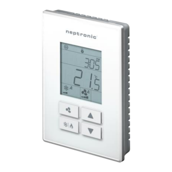
The TSUB is a universal wall-mount controller with a built-in temperature sensor. The unit is designed for simple and accurate
control of a fan coil unit or heating/cooling equipment. Its field configurable algorithms enable versatile implementation of
required control sequences.
Featuring an external humidity sensor input for accurate humidity control, this comprehensive unit also provides a
dehumidification sequence compensated by auto activation of reheat output.
The controller is available with additional sensors, such as the PIR motion detection and humidity sensor, providing more
functionality for the terminal device.
Features
•
Fan control: 1, 2 or 3-speed (auto/on), or analog (ECM)
•
Optional internal/external humidity sensor input for
simple and accurate humidity control
•
Dehumidification sequence compensated by auto
activation of reheat output
•
Real time clock (RTC) with 24-hour backup
•
7-day programmable schedule
•
Precise temperature control with configurable PI
(Proportional-Integral) function
•
Selectable internal or external temperature sensor
•
Low limit set protection (10°C / 50°F)
•
Occupancy and night set back (NSB) mode
•
Select direction on outputs
•
Select controller's default display
•
Multi-level lockable access menu and setpoint
•
Selectable Fahrenheit or Celsius scale
•
Option of pulse/floating/on-off output on binary outputs
•
Internal/external occupancy input
•
Compressor anti-cycling delay (configurable)
•
ΔT control (on request)
TSUB-200306
Networkable Universal Wall-Mount Controller
RH
PIR
●
●
●
●
Specification and Installation Instructions
TSUB00 Series
TSUB30 Series
Onboard Sensors
•
Temperature sensor (°C/°F)
•
Humidity sensor (%RH), select models
•
PIR motion detection sensor, select models
Network Communication
•
®
BACnet
MS/TP or Modbus communication port
(selectable via configuration menu)
•
Select MAC address via menu or via network
•
Automatic baud rate detection
®
BACnet MS/TP
•
Automatic device instance configuration
•
Copy & broadcast configuration via menu or via BACnet
to other controllers
•
BACnet scheduler (up to 6 events per day)
•
Firmware upgradeable via BACnet
•
Supports COV (change of value)
Modbus
•
Modbus @ 9600, 19200, 38400 or 57600 bps
•
RTU Slave, 8 bits (configurable parity and stop bits)
•
Connects to any Modbus master
TSUB60 Series
Page | 1
Advertisement
Table of Contents

Related Manuals for Neptronic TSUB00 Series


Summary of Contents for Neptronic TSUB00 Series
- Page 1 ● ● ● TSUB30-105 TSUB60-105 TSUB00 Series TSUB30 Series TSUB60 Series Description The TSUB is a universal wall-mount controller with a built-in temperature sensor. The unit is designed for simple and accurate control of a fan coil unit or heating/cooling equipment. Its field configurable algorithms enable versatile implementation of required control sequences.
-
Page 2: Technical Specifications
(Optional) B = 3.25” | 83mm C = 1.75” | 44mm D = 0.96” | 24mm E = 2.07” | 53mm F = 2.36” | 60mm G = 3.28” | 83mm H = 0.78” | 20mm www.neptronic.com Page | 2... -
Page 3: Terminal Description
Networkable Universal Wall-Mount Controller Specification and Installation Instructions Wiring We strongly recommend that all Neptronic products be wired to a separate grounded transformer and that transformer shall service only Neptronic products. This precaution will prevent interference with, and/or possible damage to incompatible equipment. -
Page 4: Mounting Instructions
The Mode Selector jumper JP1 must be set to the PGM position (Programming Mode). Refer to the Wiring section on page 3. To exit, set the jumper back to the RUN position (Operation Mode). Changes are saved as soon as they are made. Setting Value Advance to next setting Change value Return to previous setting www.neptronic.com Page | 4... -
Page 5: Symbols Used In This Manual
If set to No, the user setpoint option is not locked and the user can adjust the desired temperature setpoint. If set to yES, the user setpoint option is locked and the user cannot set the desired temperature setpoint. A lock symbol appears to indicate that the setpoint is locked. www.neptronic.com Page | 5... -
Page 6: Keypad Lock Settings
No (Disable) Range: yES (Enable), No (Disable) If set to yES, the buttons are locked and cannot be used by the user. If set to No, the buttons are unlocked and can be used by the user. www.neptronic.com Page | 6... -
Page 7: Heat Pump Settings
CH1 (Cooling and Heating). If selected, the controller performs cooling regularly. If another output is set to heat, it performs heating regularly. • HU (Humidify). If selected, the controller modulates the output based on the humidify demand. www.neptronic.com Page | 7... - Page 8 This option does not appear if the signal ramp for AO2 is set to OFF (Step 17, "AO2 Ramp"). Set the direction of the analog signal to either Direct (e.g. 0 to 10Vdc), or Reverse (e.g. 10 to 0Vdc). www.neptronic.com Page | 8...
- Page 9 (“span” value) for the AO3 ramp. The maximum value is restricted by the minimum value at Step 23, “AO3 Minimum Voltage”. In other words, the maximum value should not be less than the minimum value. www.neptronic.com Page | 9...
-
Page 10: Fan Settings
"Fan Speed Option" Default: Std (Standard) Range: AdV (Advanced), Std (Standard) Select between the Standard (Neptronic) and Advanced (OE1) fan speed specifications. The fan symbol is also displayed. "Enable Fan Contrl Mode" Default: No (Disable) Range: yES (Enable), No (Disable) This option appears only if you have selected Adv at Step 29, "Fan Speed Option". - Page 11 This option does not appear if the signal ramp for BO3 is set to OFF (Step 36, "BO3 Ramp"). Select the percentage at which you want BO3 to close (at % of demand of the ramp selected at Step 36, "BO3 Ramp"). www.neptronic.com Page | 11...
- Page 12 Range: dir (Direct), rEV (Reverse) This option does not appear if the signal ramp for BO4 is set to OFF (Step 42, "BO4 Ramp"). Set the direction of the binary signal to either Direct or Reverse. www.neptronic.com Page | 12...
- Page 13 (Pulsing), OnO (On/Off), FLot (Floating) This option does not appear if the signal ramp for BO5 is set to OFF (Step 48, "BO5 Ramp"). Select the signal type for BO5 to either Pulsing, On/Off or Floating. www.neptronic.com Page | 13...
- Page 14 Cr1, Cr2, Hr1, Hr2 (heat with fan), Hr2 (heat without fan), CH1, HU, CO2, OFF, COr Select the desired ramp from the available options. Same as BO3 options. If you select OFF, Steps 61 to 65 will not be available. www.neptronic.com Page | 14...
- Page 15 "Heat 1 Dead Band" Default: 0.3ºC [0.6ºF] Range: 0.0ºC to 5.0ºC [0ºF to 9ºF] Increment: 0.1ºC [0.2ºF] Select the desired dead band value of the heating ramp 1. The heating symbol is also displayed. www.neptronic.com Page | 15...
- Page 16 "Cl Ht Switch Timer Minutes" Default: 0 minutes Range: 0 to 120 minutes Increment: 1 minute Time required in minutes before a changeover can take place. The cooling and heating symbols are also displayed. www.neptronic.com Page | 16...
- Page 17 ΔT control mode. If you select one of the following options: OFF, t10.0, SENs, noCL, noHt, OAS, t10V, CO2, HU, P10V, or t01 Steps 82 and 83 will not be available. www.neptronic.com Page | 17...
- Page 18 This option appears if you have selected any one of the options: oVrd, win, door, dFt, FLS, oVht, SEL at Step 80, "UI1 Signal Type". Set the delay in seconds before the state of input for UI1 is changed. www.neptronic.com Page | 18...
-
Page 19: Temperature Settings
The maximum value is restricted by the minimum value set at Step 88, "Extern Temp Minimum". In other words, the value that is set as the maximum cannot be less than the minimum value. www.neptronic.com Page | 19... - Page 20 Select the setpoint value for VFD pressure. If the value is higher than 10,000, the value will be divided by 100 and shows a decimal point. The increment is displayed as 0.1. The fan symbol is also displayed. www.neptronic.com Page | 20...
- Page 21 (internal), EtS (External) Select the source for VFD temperature control. • itS. If selected, the controller will be controlled by its internal temperature sensor. • EtS. If selected, the controller will be controlled by an external temperature sensor. www.neptronic.com Page | 21...
- Page 22 Set Back (NSB) Mode, the user can override Night Set Back (NSB) (see page 34) for the duration of this delay. To disable night set back override, set the delay to 0. The moon symbol is displayed to indicate Night Set Back (NSB) Mode. www.neptronic.com Page | 22...
- Page 23 This option appears only if you have selected OCC at Step 80, "UI1 Signal Type" or Step 84, "UI2 Signal Type". Select the fan speed mode for no occupancy mode. The fan symbol is also displayed. www.neptronic.com Page | 23...
-
Page 24: Humidity Settings
Hu (Humidify only). If selected, the ramp of at least one analog or binary output must be set to Hu (humidify). If you select OFF, Steps 127 to 136 will not be available. If you select Hu or deHU, Step 127, "Humidty User Setpnt Minimum" will be available. www.neptronic.com Page | 24... - Page 25 80, "UI1 Signal Type" or Step 84, "UI2 Signal Type". Adjust the humidify setpoint during Night Set Back (NSB) Mode. The humidify setpoint is restricted by the dehumidify value at Step 132, "NSB Dehumi- Setpnt". The moon and humidify symbols are also displayed. www.neptronic.com Page | 25...
- Page 26 Cooling or OFF mode. Once the temperature reaches 5°C [41°F], the heating stops. Delta Temperature “Enable Delta Temp Mode” 138. Default: Range: On, OFF Select whether to enable or disable the ΔT control based on the inlet and outlet temperature of the water inside the fan coil unit. www.neptronic.com Page | 26...
-
Page 27: Network Settings
Select the desired MSTP MAC Address. Each device on the network must have a unique MAC address. "MSTP Max Master" 146. Default: Range: 1 to 127 Increment: Select the desired MSTP MAX address for the master device. www.neptronic.com Page | 27... - Page 28 To change the device instance, select Yes and continue to the next step. If you select No, the device instance will be modified automatically according to the MAC address (the menu starts over at Step 1, “Intern Temp Sensor Offset”). www.neptronic.com Page | 28...
- Page 29 Select the desired parity and number of stop bits for the modbus communication. "Modbus Address" 156. Default: Range: 1 to 246 Increment: Select the desired Modbus address. Each device on the network must have a unique Modbus address. www.neptronic.com Page | 29...
- Page 30 2009 to 2099 Increment: 1 year Select the year. 5. “Enter Month” Range: 01 to 12 Increment: 1 month Select the month. 6. “Set Day” Range: 01 to 31 days Increment: 1 day Select the day. www.neptronic.com Page | 30...
-
Page 31: Network Setup Menu
Page 27 to 29 These network setup steps are exactly the same as those in the Programming Mode. Please refer to Steps 142 to 156, starting on page 27. When complete, continue to the following step. www.neptronic.com Page | 31... - Page 32 Range: 10.0ºC to 40.0ºC [50ºF to 104ºF] Increment: 0.5ºC [1ºF] This option appears only if you have selected VFdt at Step 17 "AO2 Ramp". Select the setpoint value for VFD pressure. The symbol is also displayed. www.neptronic.com Page | 32...
-
Page 33: Operation Mode
• Cooling only (on, with cooling symbol) • Heating only (on, with heating symbol) • EmH (on, with heating symbol) • FAN (on, with fan symbol) • OFF (if it is not disabled in Programming Mode) www.neptronic.com Page | 33... - Page 34 User (controller is in operation), Occupied (controller is idle and occupancy state is active) and Not Occupied (controller is idle and occupancy state is inactive). Press the key to save any changes. www.neptronic.com Page | 34...
- Page 35 Notes...
- Page 36 Recycling at end of life: please return this product to your Neptronic local distributor for recycling. If you need to find the nearest Neptronic authorized distributor, please consult www.neptronic.com. 400 Lebeau blvd, Montreal, Qc, H4N 1R6, Canada www.neptronic.com Toll free in North America: 1-800-361-2308 Tel.: (514) 333-1433...
Need help?
Do you have a question about the TSUB00 Series and is the answer not in the manual?
Questions and answers