Table of Contents
Advertisement
Quick Links
Technical Data
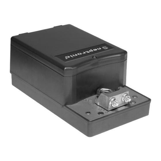
TM200FN
Auxiliary switches
Fail safe - Enerdrive
Power consumption
Torque
Running time
through 90º
Power supply
Feedback
Electrical connection
Inlet bushing
Control signal
Angle of rotation
Direction of rotation
Operating
temperature
Storage temperature
Relative Humidity
Weight
Dimensions
Caution
We strongly recommend that all Neptronic
prevent interference with, and/or possible damage to incompatible equipment.
When multiple actuators are wired on a single transformer, polarity must be observed. Long wiring runs create voltage drop which may affect the actuator performance.
1
Enerdrive System U.S.A. Patent #5,278,454
TM2FN-RM2FN_210804
Features:
•
•
•
•
•
•
•
TM220FN
TM260FN
No
Yes (2)
No
30 VA
120 in.lb. [13.5 Nm] at rated voltage
Analog, Digital or PWM programmable (factory set with analog control signal)
0 to 90 degrees, electronically adjustable (factory set with 90º stroke)
Reversible, Clockwise (CW) or Counterclockwise (CCW) (factory set with CW direction)
5 lbs. [2.3 kg]
Warning: Do not press the clutch when actuator is powered
®
products be wired to a separate transformer and that transformer shall service only Neptronic
Specification & Installation Instructions
Clutch for manual adjustments.
Maintenance free.
Position indicator.
Control signal fully programmable.
Brushless DC driven motor.
Fail safe by Enerdrive System
(on model 260 & 280).
Auxiliary switches
(on model 260 & 280).
TM280FN
RM200FN
No
Yes (2)
Yes
50 VA Peak, 30 VA
20 sec torque dependant
28 to 32 Vdc or 22 to 26 Vac, 220 to 250 Vac 50/60Hz
4 to 20 mA or 2 to 10 Vdc adjustable
2
18 AWG [0.8 mm
2 inlet bushing of 7/8 in [22.2 mm]
0ºF to 122ºF [-18ºC to 50ºC]
-22ºF to 122ºF [-30ºC to 50ºC]
5 to 95 % non condensing.
1
RM220FN
RM260FN
No
Yes (2)
No
30 VA
240 in.lb. [27 Nm] at rated voltage
] minimum
8 lbs. [3.5 kg]
Dimension
Imperial (in)
A
5.20
B
1.33
C
9.13
D
3.55
Actuator
TM200FN
TM220FN
TM260FN
TM280FN
RM200FN
RM220FN
RM260FN
RM280FN
RM280FN
No
Yes (2)
Yes
50 VA Peak, 30 VA
Metric (mm)
132.1
33.8
231.9
90.2
®
products. This precaution will
1
Advertisement
Table of Contents

Subscribe to Our Youtube Channel
Related Manuals for Neptronic TM200FN


Summary of Contents for Neptronic TM200FN
- Page 1 ® ® We strongly recommend that all Neptronic products be wired to a separate transformer and that transformer shall service only Neptronic products. This precaution will prevent interference with, and/or possible damage to incompatible equipment. When multiple actuators are wired on a single transformer, polarity must be observed. Long wiring runs create voltage drop which may affect the actuator performance.
- Page 2 TM200/220/260/280FN RM200/220/260/280FN Specification & Installation Instruction Mechanical Installation Manually close the damper blades and positioned the actuator at 0º or 90º. Slide the actuator onto the shaft. Tighten the nuts on the “U” bolt to the shaft with a 10mm wrench to a torque of 150 in.lb.
- Page 3 TM200/220/260/280FN RM200/220/260/280FN Specification & Installation Instruction PC Board Dip switch settings Potentiometer Transformer cut out Pins for PWM selection Rotation: CW Microcontroller Clutch Fail safe return at 0º Fuse Input in Vdc Feedback in mA Default Setting = All dipswitches at OFF Reset button Terminal Dip switch...
- Page 4 TM200/220/260/280FN RM200/220/260/280FN Specification & Installation Instruction Enabling or disabling PWM mode Remove power supply to actuator Install jumper between pin 3 & 4 of J3 Select the desired action using the dipswitches (DS1): DS1-1 DS1-2 Action Enable PWM Mode Disable PWM Mode Re-apply power supply to actuator Wait 5 seconds Remove power supply to actuator...
Need help?
Do you have a question about the TM200FN and is the answer not in the manual?
Questions and answers