Table of Contents
Advertisement
Models
Model
Temp
●
TSU00-110
●
TSU00-111
●
TSU00-114
●
TSU00-115
Description
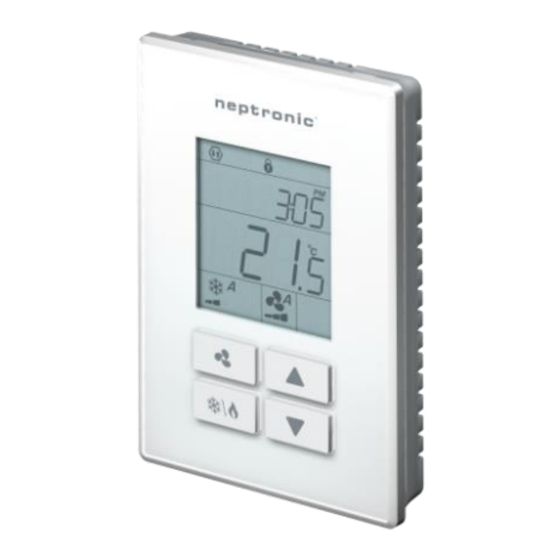
The TSU is a standalone wall-mount controller with a built-in temperature
sensor. The unit is designed for simple and accurate control of a fan coil
unit or heating/cooling equipment. Its field configurable algorithms enable
versatile implementation of required control sequences.
Featuring an external humidity sensor input for accurate humidity control,
this comprehensive unit also provides a dehumidification sequence
compensated by auto activation of reheat output.
The controller is available with additional sensors, such as the PIR motion
detection and humidity sensor, providing more functionality for the terminal
device.
Features
•
Fan control: 1, 2 or 3-speed (auto/on), or analog (ECM)
•
Optional internal/external humidity sensor input for simple and accurate humidity control
•
Dehumidification sequence compensated by auto activation of reheat output
•
Real time clock (RTC) with 24-hour backup
•
7-day programmable schedule
•
Precise temperature control with configurable PI (Proportional-Integral) function
•
Selectable internal or external temperature sensor
•
Low limit set protection (10°C / 50°F)
•
Occupancy and night set back (NSB) mode
•
Select direction on outputs
•
Select controller's default display
•
Multi-level lockable access menu and setpoint
•
Selectable Fahrenheit or Celsius scale
•
Option of pulse/floating/on-off output on binary outputs
•
Internal/external occupancy input
•
Compressor anti-cycling delay (configurable)
•
ΔT control (on request)
Onboard Sensors
•
Temperature sensor (°C/°F)
•
Humidity sensor (%RH), select models
•
PIR motion detection sensor, select models
TSU-200324
RH
PIR
●
●
●
●
Standalone Wall-Mount Controller
Specification and Installation Instructions
TSU00 Series
Page | 1
Advertisement
Table of Contents

Related Manuals for Neptronic TSU00 Series


Summary of Contents for Neptronic TSU00 Series
- Page 1 Featuring an external humidity sensor input for accurate humidity control, this comprehensive unit also provides a dehumidification sequence compensated by auto activation of reheat output. TSU00 Series The controller is available with additional sensors, such as the PIR motion detection and humidity sensor, providing more functionality for the terminal device.
-
Page 2: Technical Specifications
(Optional) B = 3.25” | 83mm C = 1.75” | 44mm D = 0.96” | 24mm E = 2.07” | 53mm F = 2.36” | 60mm G = 3.28” | 83mm H = 0.78” | 20mm www.neptronic.com Page | 2... -
Page 3: Terminal Description
Standalone Wall-Mount Controller Specification and Installation Instructions Wiring We strongly recommend that all Neptronic products be wired to a separate grounded transformer and that transformer shall service only Neptronic products. This precaution will prevent interference with, and/or possible damage to incompatible equipment. -
Page 4: Mounting Instructions
The Mode Selector jumper JP1 must be set to the PGM position (Programming Mode). Refer to the Wiring section on page 3. To exit, set the jumper back to the RUN position (Operation Mode). Changes are saved as soon as they are made. Setting Value Advance to next setting Change value Return to previous setting www.neptronic.com Page | 4... -
Page 5: Symbols Used In This Manual
The setpoint value is restricted by the minimum at Step 2, “Minimum User Setpnt” and maximum a lock symbol at Step 3, “Maximum User Setpnt” values. In other words, the setpoint should be within the minimum and maximum setpoint range. www.neptronic.com Page | 5... -
Page 6: Keypad Lock Settings
Binary Output ramps (Steps 36, 42, 48 and 54) will be available. If you select ON: • Heat Pump options (Steps 13 to 15 and 35) will be available. • Binary Output ramps (Steps 36, 42, 48 and 54) will not be available. www.neptronic.com Page | 6... - Page 7 COr (Changeover). If selected, the controller will modulate heating and cooling, as appropriate. If you select OFF, Steps 18 to 20 will not be available. If you select VFdt or VFd Steps 28 to 33 will not be available. www.neptronic.com Page | 7...
- Page 8 Select the desired signal from the available options. The AO2 input signal has priority over AO3. • Cr1 (Cooling Ramp 1) or Cr2 (Cooling Ramp 2). The Cr1 and Cr2 ramps are used for cooling. If selected, the controller performs cooling based on the cooling proportional, integral, and dead band values. www.neptronic.com Page | 8...
- Page 9 ANLg (Analog Output), OnOF (On/Off), PuLs (Pulsing) This option does not appear if the signal ramp for AO3 is set to OFF (Step 22, “AO3 Ramp”). Set the signal type for AO3 to either Analog Ouptut, On/Off or Pulsing. www.neptronic.com Page | 9...
-
Page 10: Fan Settings
"Fan Speed Option" Default: Std (Standard) Range: AdV (Advanced), Std (Standard) Select between the Standard (Neptronic) and Advanced (OE1) fan speed specifications. The fan symbol is also displayed. "Enable Fan Contrl Mode" Default: No (Disable) Range: yES (Enable), No (Disable) This option appears only if you have selected Adv at Step 29, "Fan Speed Option". - Page 11 Range: dir (Direct), rEV (Reverse) This option does not appear if the signal ramp for BO3 is set to OFF (Step 36, "BO3 Ramp"). Set the direction of the binary signal to either Direct or Reverse. www.neptronic.com Page | 11...
- Page 12 This option does not appear if the signal ramp for BO4 is set to OFF (Step 42, "BO4 Ramp"). Select the signal type BO4 to either Pulsing or On/Off. If BO3 signal type is set to Floating, then BO4 signal type will also be set to Floating. www.neptronic.com Page | 12...
- Page 13 (Delta temperature control). If selected, the controller will modulate the ΔT control based on the inlet and outlet temperature of the water inside the fan coil unit. • VFdt (VFD Temp Loop). If selected, the controller will modulate the VFD fan based on the selected temperature input. www.neptronic.com Page | 13...
- Page 14 This option does not appear if the signal ramp for BO6 is set to OFF (Step 60, “BO7 Ramp”). Select the percentage at which you want BO7 to open (at % of demand of the ramp selected at Step 60, “BO7 Ramp”). www.neptronic.com Page | 14...
- Page 15 "Heat 2 Dead Band" Default: 0.3ºC [0.6ºF] Range: 0.0ºC to 5.0ºC [0ºF to 9ºF] Increment: 0.1ºC [0.2ºF] Select the desired dead band value of the heating ramp 2. The heating symbol is also displayed. www.neptronic.com Page | 15...
- Page 16 OFF. If selected, the controller does not use the input. • t10.0. If selected, the controller uses a 10kΩ type III external temperature sensor. If you select t10.0, Step 90, "Extern Temp Sensor Offset" will be available. www.neptronic.com Page | 16...
- Page 17 ΔT control mode. If you select one of the following options: OFF, t10.0, SENs, noCL, noHt, OAS, t10V, CO2, HU, P10V, or t01 Steps 82 and 83 will not be available. t10.0 SENs noHt noCL t10V www.neptronic.com Page | 17...
- Page 18 If you select CO2, Steps 85 to 104 will not be available. If you select P10V or t10V, Step 85, "UI2 Minimum Voltage" will be available. If you select P10V, Step 95, "Pressur Maximum Range" will be available. www.neptronic.com Page | 18...
-
Page 19: Temperature Settings
Note that the heating mode activates when the temperature read by the external sensor is above the changeover setpoint and cooling mode activates when the temperature read by the external sensor is below the changeover setpoint. www.neptronic.com Page | 19... - Page 20 Select the desired proportional band value for VFD pressure. The fan symbol is also displayed. "VFD Pressur Intgral Seconds" Default: 0 seconds Range: 0 to 250 seconds Increment: 5 seconds Set the desired value for VFD pressure integral seconds. The fan symbol is also displayed. www.neptronic.com Page | 20...
- Page 21 • StP. If selected, the controller uses the NSB/No Occupancy setpoints when the window is open. • OFF. If selected, the controller is forced into OFF mode when the window is open. www.neptronic.com Page | 21...
- Page 22 Night Set Back (NSB) Mode (see page 31). The cooling setpoint value is restricted by the heating setpoint value at Step 113, "NSB Heating Setpnt". The moon and cooling symbols are also displayed. www.neptronic.com Page | 22...
- Page 23 Night Set Back (NSB) Mode/No Occupancy Mode/Window Open Mode/Door Open mode. The cooling setpoint value is restricted by the heating setpoint value at Step 119, "No OCC Heating Setpnt". The moon and cooling symbols are also displayed. www.neptronic.com Page | 23...
-
Page 24: Humidity Settings
The minimum value is restricted by the maximum value set at Step 127, "Humidty User Setpnt Maximum". In other words, the value that is set as the minimum cannot be greater than the maximum value. www.neptronic.com Page | 24... - Page 25 80, "UI1 Signal Type" or Step 84, "UI2 Signal Type". Adjust the dehumidify setpoint during No Occupancy Mode. The dehumidify setpoint is restricted by the humidify setpoint at Step 132, "No OCC Humidif Setpnt". The moon and dehumidify symbols are also displayed. www.neptronic.com Page | 25...
-
Page 26: Backlight Adjustment
“No Occ Back Light Adjust” Default: Range: 0 to 100 Increment: Select the backlight level in the not occupied mode (controller is idle and occupancy state is inactive). Use the buttons to increase or decrease the backlight level. www.neptronic.com Page | 26... - Page 27 2020 Range: 2009 to 2099 Increment: 1 year Select the year. “Enter Month” Range: 01 to 12 Increment: 1 month Select the month. “Set Day” Range: 01 to 31 days Increment: 1 day Select the day. www.neptronic.com Page | 27...
- Page 28 If --- (Null) is selected, then the controller will remain turned off and the event will be unused. To exit the Event menu, press the button. Reset Schedule “Reset Schedul” Default: Range: yES, nO Select whether to reset and delete the scheduled events or not. www.neptronic.com Page | 28...
- Page 29 Range: 10.0ºC to 40.0ºC [50ºF to 104ºF] Increment: 0.5ºC [1ºF] This option appears only if you have selected VFdt at Step 17 "AO2 Ramp". Select the setpoint value for VFD pressure. The symbol is also displayed. www.neptronic.com Page | 29...
-
Page 30: Operation Mode
• Cooling only (on, with cooling symbol) • Heating only (on, with heating symbol) • EmH (on, with heating symbol) • FAN (on, with fan symbol) • OFF (if it is not disabled in Programming Mode) www.neptronic.com Page | 30... - Page 31 User (controller is in operation), Occupied (controller is idle and occupancy state is active) and Not Occupied (controller is idle and occupancy state is inactive). Press the key to save any changes. www.neptronic.com Page | 31...
- Page 32 Recycling at end of life: please return this product to your Neptronic local distributor for recycling. If you need to find the nearest Neptronic authorized distributor, please consult www.neptronic.com. 400 Lebeau blvd, Montreal, Qc, H4N 1R6, Canada www.neptronic.com Toll free in North America: 1-800-361-2308 Tel.: (514) 333-1433...
Need help?
Do you have a question about the TSU00 Series and is the answer not in the manual?
Questions and answers