Table of Contents
Advertisement
Advertisement
Table of Contents

Related Manuals for Supermicro X11SCL-F


Summary of Contents for Supermicro X11SCL-F
- Page 1 X11SCL-F USER’S MANUAL Revision 1.0c...
- Page 2 State of California, USA. The State of California, County of Santa Clara shall be the exclusive venue for the resolution of any such disputes. Supermicro's total liability for all claims will not exceed the price paid for the hardware product.
- Page 3 About This Manual This manual is written for system integrators, IT technicians, and knowledgeable end users. It provides information for the installation and use of the X11SCL-F motherboard. About This Motherboard The Super X11SCL-F motherboard supports an Intel® Xeon® E-2200/2100, 9th/8th Generation Core i3, Pentium, and Celeron (Socket H4 - LGA 1151) series processor with up to six cores and a thermal design power (TDP) of up to 95W.
- Page 4 Super X11SCL-F User's Manual Contacting Supermicro Headquarters Address: Super Micro Computer, Inc. 980 Rock Ave. San Jose, CA 95131 U.S.A. Tel: +1 (408) 503-8000 Fax: +1 (408) 503-8008 Email: marketing@supermicro.com (General Information) support@supermicro.com (Technical Support) Website: www.supermicro.com Europe Address: Super Micro Computer B.V.
-
Page 5: Table Of Contents
Table of Contents Table of Contents Chapter 1 Introduction 1.1 Checklist ..........................8 Quick Reference .......................11 Quick Reference Table ......................12 Motherboard Features .......................14 1.2 Processor and Chipset Overview ..................18 1.3 Special Features ........................18 Recovery from AC Power Loss ..................18 1.4 System Health Monitoring ....................18 Onboard Voltage Monitors ....................18 Fan Status Monitor with Firmware Control ...............19 Environmental Temperature Control .................19... - Page 6 Super X11SCL-F User's Manual DIMM Removal .........................31 2.5 Rear I/O Ports ........................32 2.6 Front Control Panel ......................37 2.7 Connectors .........................42 Power Connections ......................42 Headers ..........................44 2.8 Jumper Settings .........................51 How Jumpers Work ......................51 2.9 LED Indicators ........................54 Chapter 3 Troubleshooting 3.1 Troubleshooting Procedures ....................57...
- Page 7 Table of Contents Appendix A BIOS Codes A.1 BIOS Error POST (Beep) Codes ..................106 Appendix B Software Installation B.1 Installing Software Programs ...................108 B.2 SuperDoctor 5 .........................109 ® Appendix C Standardized Warning Statements Appendix D UEFI BIOS Recovery D.1 Overview ...........................113 D.2 Recovering the UEFI BIOS Image ...................113 D.3 Recovering the Main BIOS Block with a USB Device .............114...
-
Page 8: Checklist
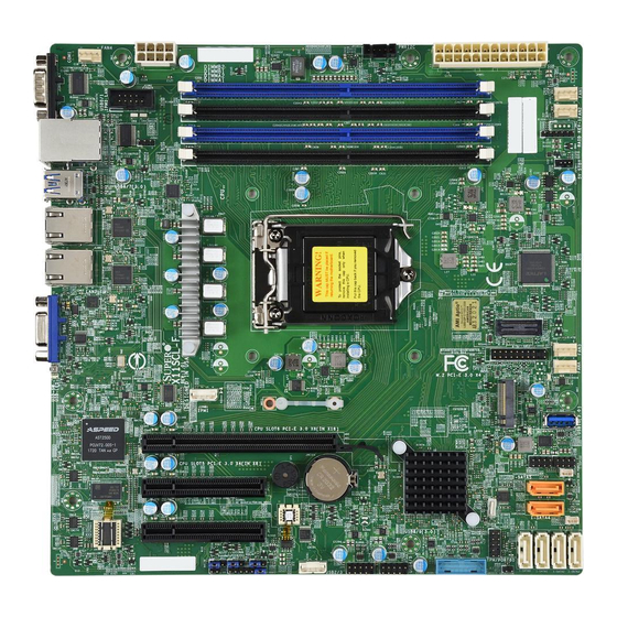
Introduction Congratulations on purchasing your computer motherboard from an industry leader. Supermicro motherboards are designed to provide you with the highest standards in quality and performance. In addition to the motherboard, several important parts that are included with your shipment are listed below. - Page 9 Chapter 1: Introduction Figure 1-1. X11SCL-F Motherboard Image Note: All graphics shown in this manual were based upon the latest PCB revision available at the time of publication of the manual. The motherboard you received may or may not look exactly the same as the graphics shown in this manual.
- Page 10 Super X11SCL-F User's Manual Figure 1-2. X11SCL-F Motherboard Layout (not drawn to scale) COM1 ASpeed LAN2 LAN1 AST2500 IPMI_LAN USB0/1 LEDBMC Intel i210 X11SCL-F REV:1.01 DESIGNED IN USA MH11 MH10 USB2/3 JBT1 USB4/5 Intel C242 MEGERAC LICENSE M.2 PCI-E 3.0 X4...
-
Page 11: Quick Reference
SLOT5 USB0/1 LAN2 LAN1 SLOT4 SLOT6 COM1 FAN4 ASpeed AST2500 LAN2 LAN1 IPMI_LAN COM2 USB0/1 LEDBMC Intel i210 JPWR2 X11SCL-F REV:1.01 JIPMB1 JOH1 DESIGNED IN USA DIMMA1 JPG1 JWD1 DIMMA2 DIMMB1 JPME2 MH11 MH11 DIMMB2 MH10 MH10 USB2/3 USB2/3 JBT1... -
Page 12: Quick Reference Table
Super X11SCL-F User's Manual Quick Reference Table Jumper Description Default Setting JBT1 CMOS Clear Open (Normal) JPG1 VGA Enable Pins 1-2 (Enabled) JPME2 ME Manufacturing Mode Pins 1-2 (Normal) JWD1 Watchdog Timer Pins 1-2 (Reset) Description Status Unit Identifier (UID) LED Solid Blue: Unit Identified M.2 LED... - Page 13 Chapter 1: Introduction Connector Description SLOT4, SLOT5 CPU PCI-E 3.0 x4 (in x8) Slots SLOT6 CPU PCI-E 3.0 x8 (in x16) Slot Onboard Buzzer USB0/1 Back Panel Universal Serial Bus (USB) 2.0 Ports USB2/3, USB4/5 Front Accessible USB 2.0 Headers USB6/7 Back Panel USB 3.1 Gen 1 Ports USB8/9...
-
Page 14: Motherboard Features
Super X11SCL-F User's Manual Motherboard Features Motherboard Features • Supports an Intel Xeon E-2200/2100, 9th/8th Generation Core i3, Pentium, and Celeron (Socket H4 - LGA 1151) series processor with a thermal design power (TDP) of up to 95W and six cores Memory •... - Page 15 Chapter 1: Introduction Motherboard Features Peripheral Devices • Two (2) USB 2.0 ports on the back I/O panel (USB0/1) • Two (2) USB 3.1 Gen 1 ports on the back I/O panel (USB6/7) • Two (2) front accessible USB 2.0 headers with two (2) USB connections each (USB2/3, USB4/5) •...
- Page 16 Note 2: For IPMI configuration instructions, please refer to the Embedded IPMI Con- figuration User's Guide available at http://www.supermicro.com/support/manuals/. Note 3: Starting in 2020, Supermicro ships standard products with a unique password that can be found on a label on the motherboard. For products shipped before 2020, the manufacturer default username is ADMIN and the password is ADMIN.
- Page 17 Chapter 1: Introduction Figure 1-3. C242 System Block Diagram IMVP 8 4 PHASE for Vcore #B-1 #B-0 #A-1 PCI-E X8 Gen3 #A-0 SLOT6 PCIe3.0 x8 (x16) #0-7 Skt-H4 PCI-E X4 Gen3 LGA1151 SLOT5 PCIe3.0 x4 (x8) #8-11 #12-15 DMI3 PCI-E X4 Gen3 SLOT4 PCIe3.0 x4 (x8) DMI3 x4...
-
Page 18: Processor And Chipset Overview
The X11SCL-F offers maximum I/O flexibility and data reliability in a 14-nm process architecture and is ideal for SMB, embedded storage solutions, and cloud-computing platforms. -
Page 19: Fan Status Monitor With Firmware Control
Chapter 1: Introduction Fan Status Monitor with Firmware Control The system health monitor embedded in the BMC chip can check the RPM status of the cooling fans. The CPU and chassis fans are controlled via lPMI. Environmental Temperature Control System Health sensors in the BMC monitor the temperatures and voltage settings of onboard processors and the system in real time via the IPMI interface. -
Page 20: Power Supply
It is even more important for processors that have high CPU clock rates where noisy power transmission is present. The X11SCL-F motherboard accommodates a 24-pin ATX power supply. Although most power supplies generally meet the specifications required by the CPU, some are inadequate. In addition, one 12V 8-pin power connection is also required to ensure adequate power to the system. -
Page 21: Chapter 2 Installation
Chapter 2: Installation Chapter 2 Installation 2.1 Static-Sensitive Devices Electrostatic Discharge (ESD) can damage electronic com ponents. To avoid damaging your system board, it is important to handle it very carefully. The following measures are generally sufficient to protect your equipment from ESD. Precautions •... -
Page 22: Motherboard Installation
Super X11SCL-F User's Manual 2.2 Motherboard Installation All motherboards have standard mounting holes to fit different types of chassis. Make sure that the locations of all the mounting holes for both the motherboard and the chassis match. Although a chassis may have both plastic and metal mounting fasteners, metal ones are highly recommended because they ground the motherboard to the chassis. -
Page 23: Installing The Motherboard
Chapter 2: Installation Installing the Motherboard 1. Install the I/O shield into the back of the chassis, if applicable. 2. Locate the mounting holes on the motherboard. See the previous page for the location. 3. Locate the matching mounting holes on the chassis. Align the mounting holes on the motherboard against the mounting holes on the chassis. -
Page 24: Processor And Heatsink Installation
CPU socket and none of the socket pins are bent. If they are, contact your retailer. • Refer to the Supermicro website for updates on CPU support. Installing the LGA 1151 Processor 1. Press the load lever down to release the load plate from its locking position. - Page 25 Chapter 2: Installation 2. Gently lift the load lever to open the load plate. Remove the plastic protective cover. Do not touch the CPU socket contacts. 3. Locate the triangle on the CPU and CPU socket, which indicates the location of Pin 1. Holding the CPU by the edges with your thumb and index finger, align the triangle on the CPU with the triangle on the socket.
-
Page 26: Installing An Active Cpu Heatsink With Fan
Super X11SCL-F User's Manual 5. Close the load plate, then gently push down the load lever into its locking position. CPU properly installed Load lever locked into place Note: You can only install the CPU in one direction. Make sure it is properly inserted into the socket before closing the load plate. - Page 27 Chapter 2: Installation 6. Align the four heatsink fasteners with the mounting holes on the motherboard. Gently push down the fasteners in a diagonal order (Example: #1 and #2, then #3 and #4) into the mounting holes until you hear a click. Then lock the fasteners by turning each one 90°...
-
Page 28: Removing The Heatsink
Super X11SCL-F User's Manual Removing the Heatsink Note: We do not recommend that the CPU or heatsink be removed. However, if you do need to remove the heatsink, please follow the instructions below to remove the heatsink and prevent damage done to the CPU or other components. -
Page 29: Memory Support And Installation
DIMM modules to prevent any damage. Memory Support The X11SCL-F supports up to 128GB of unbuffered (UDIMM) DDR4 (288-pin) ECC memory (2-DIMM per channel) with speeds of up to 2666MHz in four memory slots. Refer to the tables below for the recommended DIMM population order and additional memory information. -
Page 30: General Guidelines For Optimizing Memory Performance
Super X11SCL-F User's Manual General Guidelines for Optimizing Memory Performance • The blue slots must be populated first. • Always use DDR4 memory of the same type, size, and speed. • Mixed DIMM speeds can be installed. However, all DIMMs will run at the speed of the slowest DIMM. -
Page 31: Dimm Installation
LAN2 LAN1 IPMI_LAN USB0/1 into the memory slots based on the LEDBMC Intel i210 X11SCL-F recommended DIMM population table on REV:1.01 DESIGNED IN USA page 29. MH11 2. Push the release tabs outwards on both MH10 ends of the DIMM slot to unlock it. -
Page 32: Rear I/O Ports
Super X11SCL-F User's Manual 2.5 Rear I/O Ports See the layout below for the locations and descriptions of the various I/O ports on the rear of the motherboard. COM1 ASpeed AST2500 LAN2 LAN1 IPMI_LAN USB0/1 LEDBMC Intel i210 X11SCL-F REV:1.01... - Page 33 VGA display. 1. COM1 COM1 2. COM2 ASpeed AST2500 LAN2 LAN1 IPMI_LAN USB0/1 3. VGA Port LEDBMC Intel i210 X11SCL-F REV:1.01 DESIGNED IN USA MH11 MH10 USB2/3 JBT1 USB4/5 Intel C242 MEGERAC LICENSE M.2 PCI-E 3.0 X4 JTPM1 MAC CODE...
- Page 34 Super X11SCL-F User's Manual Universal Serial Bus (USB) Ports There are two USB 2.0 ports (USB0/1) and two USB 3.1 Gen 1 ports (USB6/7) located on the back I/O panel. The motherboard also has two front access USB 2.0 headers (USB2/3, USB4/5) and one front access USB 3.1 Gen 1 header (USB8/9).
- Page 35 SGND TD3- 1. LAN1 COM1 2. LAN2 ASpeed AST2500 LAN2 LAN1 IPMI_LAN USB0/1 3. IPMI LAN LEDBMC Intel i210 X11SCL-F REV:1.01 DESIGNED IN USA MH11 MH10 USB2/3 JBT1 USB4/5 Intel C242 MEGERAC LICENSE M.2 PCI-E 3.0 X4 JTPM1 MAC CODE...
- Page 36 Super X11SCL-F User's Manual Unit Identifier Switch/UID LED Indicator A Unit Identifier (UID) switch and an LED indicator are located on the motherboard. The UID switch is located at JUIDB1, which is next to the VGA port on the back panel. The UID LED (LE1) is located next to the UID switch.
-
Page 37: Front Control Panel
JF1 contains header pins for various buttons and indicators that are normally located on a control panel at the front of the chassis. These connectors are designed specifically for use with Supermicro chassis. See the figure below for the descriptions of the front control panel buttons and LED indicators. - Page 38 Super X11SCL-F User's Manual Power Button The Power Button connection is located on pins 1 and 2 of JF1. Momentarily contacting both pins will power on/off the system. This button can also be configured to function as a suspend button (with a setting in the BIOS - see Chapter 4). To turn off the power when the system is in suspend mode, press the button for four seconds or longer.
- Page 39 Chapter 2: Installation Power Fail LED The Power Fail LED connection is located on pins 5 and 6 of JF1. Refer to the table below for pin definitions. Power Fail LED Pin Definitions (JF1) Pin# Definition 3.3V PWR Supply Fail Ovearheat/Fan Fail and UID LED Connect an LED cable to pins 7 and 8 of the Front Control Panel to use the Overheat/Fan Fail LED connections.
- Page 40 Super X11SCL-F User's Manual NIC1/NIC2 (LAN1/LAN2) The Network Interface Controller (NIC) LED connection for LAN port 1 is located on pins 11 and 12 of JF1, and LAN port 2 is on pins 9 and 10. Attach the NIC LED cables here to display network activity.
- Page 41 Chapter 2: Installation Power LED The Power LED connection is located on pins 15 and 16 of JF1. Refer to the table below for pin definitions. Power LED Pin Definitions (JF1) Pin# Definition 3.3V PWR LED NMI Button The non-maskable interrupt (NMI) button header is located on pins 19 and 20 of JF1. Refer to the table below for pin definitions.
-
Page 42: Connectors
Super X11SCL-F User's Manual 2.7 Connectors Power Connections ATX Power Supply Connector The primary 24-pin power supply connector (JPWR1) meets the ATX SSI EPS 12V specification. An 8-pin (JPWR2) processor power connector must also be connected to your power supply. - Page 43 1. 8-pin PWR COM1 ASpeed AST2500 LAN2 LAN1 IPMI_LAN USB0/1 LEDBMC Intel i210 X11SCL-F REV:1.01 DESIGNED IN USA MH11 MH10 USB2/3 JBT1 USB4/5 Intel C242 MEGERAC LICENSE M.2 PCI-E 3.0 X4...
-
Page 44: Headers
Super X11SCL-F User's Manual Headers Fan Headers There are five 4-pin fan headers (FAN1 ~ FAN4, FANA) on the motherboard. All these 4-pin fan headers are backwards compatible with the traditional 3-pin fans. However, fan speed control is available for 4-pin fans only by Thermal Management via the IPMI 2.0 interface. - Page 45 SPI_IRQ# M.2 Slot The X11SCL-F motherboard has one M.2 slot. M.2 was formerly known as Next Generation Form Factor (NGFF) and serves to replace mini PCI-E. M.2 allows for a variety of card sizes, increased functionality, and spatial efficiency. The M.2 socket on the motherboard supports SSD cards in a 2280 / 22110 form factor.
- Page 46 Super X11SCL-F User's Manual Standby Power The Standby Power header is located at JSTBY1 on the motherboard. You must have a card with a Standby Power connector and a cable to use this feature. Refer to the table below for pin definitions.
- Page 47 NC = No Connection 1. Chassis Intrusion Header COM1 2. I-SGPIO1 Header ASpeed AST2500 LAN2 LAN1 IPMI_LAN USB0/1 3. I-SGPIO2 Header LEDBMC Intel i210 X11SCL-F REV:1.01 DESIGNED IN USA MH11 MH10 USB2/3 JBT1 USB4/5 Intel C242 MEGERAC LICENSE M.2 PCI-E 3.0 X4 JTPM1...
- Page 48 Super X11SCL-F User's Manual 4-pin BMC External I C Header A System Management Bus header for IPMI 2.0 is located at JIPMB1. Connect the appropriate cable here to use the IPMB I C connection on your system. Refer to the table below for pin definitions.
- Page 49 R_SPKPIN 1. Onboard Buzzer COM1 2. Power LED Indicator/ ASpeed AST2500 LAN2 LAN1 IPMI_LAN Speaker Header USB0/1 LEDBMC Intel i210 X11SCL-F REV:1.01 DESIGNED IN USA MH11 MH10 USB2/3 JBT1 USB4/5 Intel C242 MEGERAC LICENSE M.2 PCI-E 3.0 X4 JTPM1 MAC CODE...
- Page 50 Super X11SCL-F User's Manual SATA Ports The X11SCL-F has six SATA 3.0 ports (I-SATA0 ~ I-SATA5) supported by the Intel C242 chipset. These SATA ports support RAID 0, 1, 5, and 10. SATA ports provide serial-link signal connections, which are faster than the connections of Parallel ATA.
-
Page 51: Jumper Settings
Chapter 2: Installation 2.8 Jumper Settings How Jumpers Work To modify the operation of the motherboard, jumpers can be used to choose between optional settings. Jumpers create shorts between two pins to change the function of the connector. Pin 1 is identified with a square solder pad on the printed circuit board. See the diagram below for an example of jumping pins 1 and 2. - Page 52 Super X11SCL-F User's Manual ME Manufacturing Mode Close pins 2-3 of jumper JPME2 to bypass SPI flash security and force the system to operate in the manufacturing mode, which will allow the user to flash the system firmware from a host server for system setting modifications.
- Page 53 Pins 1-2 Enabled Pins 2-3 Disabled 1. VGA Enable COM1 ASpeed AST2500 LAN2 LAN1 IPMI_LAN USB0/1 LEDBMC Intel i210 X11SCL-F REV:1.01 DESIGNED IN USA MH11 MH10 USB2/3 JBT1 USB4/5 Intel C242 MEGERAC LICENSE M.2 PCI-E 3.0 X4 JTPM1 MAC CODE...
-
Page 54: Led Indicators
Super X11SCL-F User's Manual 2.9 LED Indicators LAN LEDs Two LAN ports (LAN 1, LAN 2) are located on the back I/O panel of the motherboard. Each Ethernet LAN port has two LEDs. The green LED indicates activity, while the other Link LED may be green, amber, or off to indicate the speed of the connection. - Page 55 BMC Normal Blinking 1. IPMI LAN LED COM1 2. BMC Heartbeat LED ASpeed AST2500 LAN2 LAN1 IPMI_LAN USB0/1 LEDBMC Intel i210 X11SCL-F REV:1.01 DESIGNED IN USA MH11 MH10 USB2/3 JBT1 USB4/5 Intel C242 MEGERAC LICENSE M.2 PCI-E 3.0 X4 JTPM1...
- Page 56 Super X11SCL-F User's Manual Onboard Power LED The Onboard Power LED is located at LEDPWR on the motherboard. When this LED is on, the system is on. Be sure to turn off the system and unplug the power cord before removing or installing components.
-
Page 57: Chapter 3 Troubleshooting
Chapter 3: Troubleshooting Chapter 3 Troubleshooting 3.1 Troubleshooting Procedures Use the following procedures to troubleshoot your system. If you have followed all of the procedures below and still need assistance, refer to the "Technical Support Procedures" and/ or "Returning Merchandise for Service" section(s) in this chapter. Always disconnect the AC power cord before adding, changing or installing any non hot-swap hardware components. -
Page 58: No Video
Super X11SCL-F User's Manual No Video 1. If the power is on, but there is no video, remove all add-on cards and cables. 2. Use the speaker to determine if any beep codes are detected. Refer to Appendix A for details on beep codes. -
Page 59: Losing The System's Setup Configuration
Chapter 3: Troubleshooting Losing the System's Setup Configuration 1. Make sure that you are using a high-quality power supply. A poor-quality power supply may cause the system to lose the CMOS setup information. Refer to Chapter 2 for details on recommended power supplies. 2. - Page 60 Super X11SCL-F User's Manual 3. Using the minimum configuration for troubleshooting: Remove all unnecessary components (starting with add-on cards), and use the minimum configuration (but with a CPU and memory module installed) to identify the trouble areas. Refer to the steps listed in Section A for proper troubleshooting procedures.
-
Page 61: Technical Support Procedures
Before contacting Technical Support, please follow the steps below. Note that as a motherboard manufacturer, Supermicro sells motherboards through various channels, so it is best to first check with your distributor or reseller for troubleshooting services. They should know of any possible problems with the specific system configuration that was sold to you. -
Page 62: Frequently Asked Questions
Note: The SPI BIOS chip used on this motherboard cannot be removed. Send your motherboard back to our RMA department at Supermicro for repair. For BIOS Recov- ery instructions, please refer to the AMI BIOS Recovery Instructions at http://www. -
Page 63: Battery Removal And Installation
Chapter 3: Troubleshooting 3.4 Battery Removal and Installation Battery Removal To remove the onboard battery, follow the steps below: 1. Power off your system and unplug your power cable. 2. Using a tool such as a pen or a small screwdriver, push the battery lock outwards to unlock it. -
Page 64: Returning Merchandise For Service
Super X11SCL-F User's Manual 3.5 Returning Merchandise for Service A receipt or copy of your invoice marked with the date of purchase is required before any warranty service will be rendered. You can obtain service by calling your vendor for a Returned Merchandise Authorization (RMA) number. -
Page 65: Chapter 4 Bios
Chapter 4: BIOS Chapter 4 BIOS 4.1 Introduction This chapter describes the AMIBIOS™ Setup utility for the motherboard. The BIOS is stored on a chip and can be easily upgraded using a flash program. Note: Due to periodic changes to the BIOS, some settings may have been added or deleted and might not yet be recorded in this manual. -
Page 66: Main Setup
Super X11SCL-F User's Manual 4.2 Main Setup When you first enter the AMI BIOS setup utility, you will enter the Main setup screen. You can always return to the Main setup screen by selecting the Main tab. The Main BIOS setup screen is shown below. - Page 67 Chapter 4: BIOS CPLD Version This item displays the Complex Programmable Logic Device version. Memory Information Total Memory This item displays the total size of memory available in the system.
-
Page 68: Advanced Setup Configurations
Super X11SCL-F User's Manual 4.3 Advanced Setup Configurations Use the arrow keys to select the Advanced menu and press <Enter> to access the submenu features: Warning: Take caution when changing the Advanced settings. An incorrect value, a very high DRAM frequency, or an incorrect DRAM timing setting may make the system unstable. When this occurs, revert to default manufacturer settings. - Page 69 Chapter 4: BIOS Option ROM Messages Use this feature to set the display mode for the Option ROM. Select Keep Current to display the current AddOn ROM setting. Select Force BIOS to use the Option ROM display set by the system BIOS. The options are Force BIOS and Keep Current. Wait For "F1"...
- Page 70 Super X11SCL-F User's Manual CPU Configuration The following CPU information will display: • Type • CPU Signature • Microcode Revision • CPU Speed • L1 Data Cache • L1 Instruction Cache • L2 Cache • L3 Cache • L4 Cache •...
- Page 71 Chapter 4: BIOS Intel (VMX) Virtualization Technology Use this feature to enable the Vanderpool Technology. This technology allows the system to run several operating systems simultaneously. The options are Disabled and Enabled. Active Processor Cores This feature determines how many CPU cores will be activated for each CPU. When All is selected, all cores in the CPU will be activated.
- Page 72 Super X11SCL-F User's Manual Turbo Mode This feature will enable dynamic control of the processor, allowing it to run above stock fre- quency. The options are Disabled and Enabled. Monitor/Mwait Select Enabled to enable the Monitor/Mwait instructions. The Monitor instructions monitor a region of memory for writes, while MWait instructions instruct the CPU to stop until the moni- tored region begins to write.
- Page 73 Chapter 4: BIOS Chipset Configuration Warning: Setting the wrong values in the following features may cause the system to malfunc- tion. System Agent (SA) Configuration The following information is displayed: • SA PCIe Code Version • VT-d Memory Configuration • Memory RC Version •...
- Page 74 Super X11SCL-F User's Manual Fast Boot Use this feature to enable or disable fast path through the memory reference code (MRC). The options are Disabled and Enabled. REFRESH_2X_MODE Use this feature to select the memory controller 2x refresh rate mode. The options are Disabled, 1- Enabled for WARM or HOT, and 2- Enabled HOT only.
- Page 75 Chapter 4: BIOS Power Limit Scale Use this feature to select the scale used for the slot power limit value. The options are 1.0x, 0.1x, 0.01x, and 0.001x. Physical Slot Number Use this feature to set the physical slot number attached to this port. Press "+" or "-" on your keyboard to change the setting to a value between 0-8191.
- Page 76 Super X11SCL-F User's Manual PCH-IO Configuration PCI Express Configuration DMI Link ASPM Control Use this feature to set the Active State Power Management (ASPM) state on the System Agent (SA) side of the DMI Link. The options are Disable, L0s, L1, L0sL1, and Auto.
- Page 77 Chapter 4: BIOS Serial Port 2 Configuration This submenu allows the user to configure the settings of Serial Port 2. Serial Port 2 Select Enabled to enable the selected onboard serial port. The options are Disabled and Enabled. Device Settings This item displays the status of a serial port specified by the user. Change Settings This feature specifies the base I/O port address and the Interrupt Request address of a serial port specified by the user.
- Page 78 Super X11SCL-F User's Manual COM1 Bits Per Second Use this feature to set the transmission speed for a serial port used in Console Redirection. Make sure that the same speed is used in the host computer and the client computer. A lower transmission speed may be required for long and busy lines.
- Page 79 Chapter 4: BIOS COM1 Putty KeyPad This feature selects the settings for Function Keys and KeyPad used for Putty, which is a terminal emulator designed for the Windows OS. The options are VT100, LINUX, XTERMR6, SC0, ESCN, and VT400. COM1 Redirection After POST Use this feature to enable or disable legacy console redirection after BIOS POST.
- Page 80 Super X11SCL-F User's Manual SOL Parity A parity bit can be sent along with regular data bits to detect data transmission errors. Select Even if the parity bit is set to 0, and the number of 1's in data bits is even. Select Odd if the parity bit is set to 0, and the number of 1's in data bits is odd.
- Page 81 Chapter 4: BIOS SOL Redirection After POST Use this feature to enable or disable legacy console redirection after BIOS POST. When set to BootLoader, legacy console redirection is disabled before booting the OS. When set to Always Enable, legacy console redirection remains enabled when booting the OS. The options are Always Enable and BootLoader.
- Page 82 Super X11SCL-F User's Manual EMS Terminal Type Use this feature to select the target terminal emulation type for Console Redirection. Select VT100 to use the ASCII character set. Select VT100+ to add color and function key support. Select ANSI to use the extended ASCII character set. Select VT-UTF8 to use UTF8 encoding to map Unicode characters into one or more bytes.
- Page 83 Chapter 4: BIOS Aggressive LPM Support When Aggresive Link Power Management (LPM) support is set to Enabled, the SATA AHCI controller manages the power usage of the SATA link. The controller will put the link in a low power mode during extended periods of I/O inactivity, and will return the link to an active state when I/O activity resumes.
- Page 84 Super X11SCL-F User's Manual PCH-FW Configuration The following firmware information will display: • Operational Firmware Version • Backup Firmware Version • Recovery Firmware Version • ME Firmware Features • ME Firmware Status #1 • ME Firmware Status #2 • Current State •...
- Page 85 Chapter 4: BIOS USB Configuration The following USB items will be displayed: • USB Module Version • USB Controllers • USB Devices Legacy USB Support (Available when USB Functions are not Disabled) Select Enabled to support legacy USB devices. Select Auto to disable legacy support if USB devices are not present.
- Page 86 Super X11SCL-F User's Manual VGA Priority Use this feature to select VGA priority when multiple VGA devices are detected. Select On- board to give priority to your onboard video device. Select Offboard to give priority to your graphics card. The options are Onboard and Offboard.
- Page 87 Chapter 4: BIOS Onboard LAN Option ROM Type Use this feature to select which firmware type to be loaded for onboard LAN ports. The options are Legacy and EFI. *If the feature above is set to Legacy, the following LAN ports will be listed and become available for configuration: Onboard LAN1 ~ LAN2 Option ROM Use this feature to select which firmware function to be loaded for the specified onboard LAN...
- Page 88 Super X11SCL-F User's Manual Trusted Computing The X11SCL-F supports TPM 1.2 and 2.0. The following Trusted Platform Module (TPM) information will display if a TPM 2.0 module is detected: • Firmware Version • Vendor Name Security Device Support If this feature and the TPM jumper on the motherboard are both set to Enable, onboard security devices will be enabled for TPM (Trusted Platform Module) support to enhance data integrity and network security.
- Page 89 TPM 2.0 will restrict support for TPM 2.0 devices. Select Auto to enable support for both versions. The options are TPM 1.2, TPM 2.0, and Auto. SMCI BIOS-Based TPM Provision Support Use this feature to enable the Supermicro TPM Provision support. The options are Disabled and Enabled. TXT Support Intel Trusted Execution Technology (TXT) helps protect against software-based attacks and ensures protection, confidentiality, and integrity of data stored or created on the system.
- Page 90 Super X11SCL-F User's Manual iSCSI Configuration This submenu is available for configuration when "Network Stack" is enabled under the sub- menu, "PCIe/PCI/PnP Configuration". iSCSI Initiator Name This feature allows the user to enter the unique name of the iSCSI Initiator in IQN format.
-
Page 91: Event Logs
Chapter 4: BIOS 4.4 Event Logs Use this feature to configure Event Log settings. Change SMBIOS Event Log Settings Enabling/Disabling Options SMBIOS Event Log Change this feature to enable or disable all features of the SMBIOS Event Logging during system boot. The options are Disabled and Enabled. Erasing Settings Erase Event Log If No is selected, data stored in the event log will not be erased. - Page 92 Super X11SCL-F User's Manual SMBIOS Event Log Standard Settings Log System Boot Event This feature toggles the System Boot Event logging to enabled or disabled. The options are Enabled and Disabled. MECI The Multiple Event Count Increment (MECI) counter counts the number of occurences that a duplicate event must happen before the MECI counter is incremented.
-
Page 93: Ipmi
Chapter 4: BIOS 4.5 IPMI Use this feature to configure Intelligent Platform Management Interface (IPMI) settings. BMC Firmware Revision This item indicates the IPMI firmware revision used in your system. IPMI Status (Baseboard Management Controller) This item indicates the status of the IPMI firmware installed in your system. System Event Log Enabling/Disabling Options SEL Components... - Page 94 Super X11SCL-F User's Manual When SEL is Full This feature allows the user to decide what the BIOS should do when the system event log is full. Select Erase Immediately to erase all events in the log when the system event log is full.
- Page 95 Chapter 4: BIOS Station MAC Address This feature displays the Station MAC address for this computer. Mac addresses are 6 two- digit hexadecimal numbers. Gateway IP Address This feature displays the Gateway IP address for this computer. This should be in decimal and in dotted quad form (i.e., 172.31.0.1).
-
Page 96: Security
Super X11SCL-F User's Manual 4.6 Security This menu allows the user to configure the following security settings for the system. Password Check Select Setup for the system to check for a password at Setup. Select Always for the system to check for a password at bootup or upon entering the BIOS Setup utility. The options are Setup and Always. - Page 97 Chapter 4: BIOS CSM Support Select Enabled to support the EFI Compatibility Support Module (CSM), which provides compatibility support for traditional legacy BIOS for system boot. The options are Disabled and Enabled. Key Management This submenu allows the user to configure the following Key Management settings. ...
- Page 98 Super X11SCL-F User's Manual Key Exchange Keys Update Select Yes to load the KEK from the manufacturer's defaults. Select No to load the KEK from a file. The options are Yes and No. Append Select Yes to add the KEK from the manufacturer's defaults list to the existing KEK.
- Page 99 Chapter 4: BIOS OsRecovery Signature This feature uploads and installs an OSRecovery Signature. You may insert a factory default key or load from a file. The file formats accepted are: 1) Public Key Certificate a. EFI Signature List b. EFI CERT X509 (DER Encoded) c.
-
Page 100: Boot
Super X11SCL-F User's Manual 4.7 Boot Use this feature to configure Boot settings. Setup Prompt Timeout Use this feature to indicate the length of time (the number of seconds) for the BIOS to wait before rebooting the system when the setup activation key is pressed. Enter the value of 65535 (0xFFFF) for the BIOS to wait indefinitely. - Page 101 Chapter 4: BIOS • Legacy/UEFI/Dual Boot Option #5 • Legacy/UEFI/Dual Boot Option #6 • Legacy/UEFI/Dual Boot Option #7 • Legacy/UEFI/Dual Boot Option #8 • UEFI/Dual Boot Option #9 • Dual Boot Option #10 • Dual Boot Option #11 • Dual Boot Option #12 •...
- Page 102 Super X11SCL-F User's Manual Path for Boot Option Use this feature to enter the path for the new boot option in the format fsx:\path\filename.efi. Boot Option File Path Use this feature to specify the file path for the new boot option.
- Page 103 Chapter 4: BIOS UEFI Hard Disk Drive BBS Priorities This feature sets the system boot order of detected devices. • Boot Option #1 Hard Disk Drive BBS Priorities This feature sets the system boot order of detected devices. •...
-
Page 104: Save & Exit
Super X11SCL-F User's Manual 4.8 Save & Exit Select the Save & Exit tab from the BIOS setup screen to configure the settings below: Save Options Discard Changes and Exit Select this feature to quit the BIOS Setup without making any permanent changes to the system configuration and reboot the computer. - Page 105 Chapter 4: BIOS Default Options Restore Defaults To set this feature, select Restore Defaults from the Save & Exit menu and press <Enter>. These are factory settings designed for maximum system stability, but not for maximum performance. Save As User Defaults To set this feature, select Save as User Defaults from the Save &...
-
Page 106: Appendix A Bios Codes
Super X11SCL-F User's Manual Appendix A BIOS Codes A.1 BIOS Error POST (Beep) Codes During the POST (Power-On Self-Test) routines, which are performed each time the system is powered on, errors may occur. Non-fatal errors are those which, in most cases, allow the system to continue the boot-up process. - Page 107 When the BIOS performs the Power On Self Test, it writes checkpoint codes to I/O port 0080h. If the computer cannot complete the boot process, a diagnostic card can be attached to the computer to read I/O port 0080h (Supermicro p/n AOM-SPI80-V). For information on AMI updates, please refer to http://www.ami.com/products/.
-
Page 108: Appendix B Software Installation
The Supermicro website contains drivers and utilities for your system at https://www. supermicro.com/wftp/driver. Some of these must be installed, such as the chipset driver. After accessing the website, go into the CDR_Images (in the parent directory of the above link) and locate the ISO file for your motherboard. Download this file to create a DVD of the drivers and utilities it contains. -
Page 109: Superdoctor ® 5
B.2 SuperDoctor ® The Supermicro SuperDoctor 5 is a program that functions in a command-line or web-based interface for Windows and Linux operating systems. The program monitors such system health information as CPU temperature, system voltages, system power consumption, fan speed, and provides alerts via email or Simple Network Management Protocol (SNMP). -
Page 110: Appendix C Standardized Warning Statements
The following statements are industry standard warnings, provided to warn the user of situations which have the potential for bodily injury. Should you have questions or experience difficulty, contact Supermicro's Technical Support department for assistance. Only certified technicians should attempt to install or configure components. - Page 111 Appendix C: Standardized Warning Statements Attention Danger d'explosion si la pile n'est pas remplacée correctement. Ne la remplacer que par une pile de type semblable ou équivalent, recommandée par le fabricant. Jeter les piles usagées conformément aux instructions du fabricant. ¡Advertencia! Existe peligro de explosión si la batería se reemplaza de manera incorrecta.
- Page 112 Super X11SCL-F User's Manual Product Disposal Warning! Ultimate disposal of this product should be handled according to all national laws and regulations. 製品の廃棄 この製品を廃棄処分する場合、 国の関係する全ての法律 ・ 条例に従い処理する必要があります。 警告 本产品的废弃处理应根据所有国家的法律和规章进行。 警告 本產品的廢棄處理應根據所有國家的法律和規章進行。 Warnung Die Entsorgung dieses Produkts sollte gemäß allen Bestimmungen und Gesetzen des Landes erfolgen.
-
Page 113: Appendix D Uefi Bios Recovery
Warning: Do not upgrade the BIOS unless your system has a BIOS-related issue. Flashing the wrong BIOS can cause irreparable damage to the system. In no event shall Supermicro be liable for direct, indirect, special, incidental, or consequential damages arising from a BIOS update. -
Page 114: Recovering The Main Bios Block With A Usb Device
1. Please use a different machine to download the BIOS package for your motherboard or your system from the product page available on our website at www.supermicro.com. 2. Extract the BIOS package to a USB device and rename the BIOS ROM file [BIOSname#.###] that is included in the BIOS package to SUPER.ROM for BIOS... - Page 115 Appendix D: UEFI BIOS Recovery 5. After locating the SUPER.ROM file, the system will enter the BIOS Recovery menu as shown below. Note: At this point, you may decide if you want to start the BIOS recovery. If you decide to proceed with BIOS recovery, follow the procedures below.
- Page 116 Super X11SCL-F User's Manual 7. After the BIOS recovery process is complete, press any key to reboot the system. Note: It is recommended that you update your BIOS after BIOS recovery. Please refer to Chapter 3 for BIOS update instructions.
- Page 117 Appendix D: UEFI BIOS Recovery 9. When the UEFI Shell prompt appears, type fs# to change the device directory path. Go to the directory that contains the BIOS package you extracted earlier in Step 2. Enter flash.nsh BIOSname#.### at the prompt to start the BIOS update process. Note: Do not interrupt this process until the BIOS flashing is complete.
Need help?
Do you have a question about the X11SCL-F and is the answer not in the manual?
Questions and answers