Table of Contents
Advertisement
Quick Links
Advertisement
Table of Contents

Related Manuals for Supermicro X11SCQ-L


Summary of Contents for Supermicro X11SCQ-L
- Page 1 X11SCQ/-L USER’S MANUAL Revision 1.0...
- Page 2 State of California, USA. The State of California, County of Santa Clara shall be the exclusive venue for the resolution of any such disputes. Supermicro's total liability for all claims will not exceed the price paid for the hardware product.
- Page 3 Please note that this motherboard is intended to be installed and serviced by professional technicians only. For processor and memory updates, please refer to our website at http:// www.supermicro.com/products/. Manual Organization Chapter 1 describes the features, specifications and performance of the motherboard, and provides detailed information on the Q370/H310 chipset.
- Page 4 Super X11SCQ/-L User's Manual Contacting Supermicro Headquarters Address: Super Micro Computer, Inc. 980 Rock Ave. San Jose, CA 95131 U.S.A. Tel: +1 (408) 503-8000 Fax: +1 (408) 503-8008 Email: marketing@supermicro.com (General Information) support@supermicro.com (Technical Support) Website: www.supermicro.com Europe Address: Super Micro Computer B.V.
-
Page 5: Table Of Contents
Table of Contents Table of Contents Chapter 1 Introduction 1.1 Checklist ..........................8 Quick Reference Table ......................12 Motherboard Features .......................14 1.2 Processor and Chipset Overview ..................18 1.3 Special Features ........................18 Recovery from AC Power Loss ..................18 1.4 System Health Monitoring ....................19 Onboard Voltage Monitors ....................19 Fan Status Monitor with Firmware Control ...............19 Environmental Temperature Control .................19... - Page 6 Super X11SCQ/-L User's Manual DIMM Removal .........................30 2.5 Rear I/O Ports ........................31 2.6 Front Control Panel ......................36 2.7 Connectors .........................40 2.8 Jumper Settings .........................51 How Jumpers Work ......................51 2.9 LED Indicators ........................56 Chapter 3 Troubleshooting 3.1 Troubleshooting Procedures ....................57 Before Power On ......................57 No Power ..........................57 No Video ...........................58 System Boot Failure ......................58...
- Page 7 Table of Contents Appendix A BIOS Codes A.1 BIOS Error POST (Beep) Codes ..................111 Appendix B Software Installation B.1 Installing Software Programs ...................113 B.2 SuperDoctor 5 .........................114 ® Appendix C Standardized Warning Statements Appendix D UEFI BIOS Recovery...
-
Page 8: Checklist
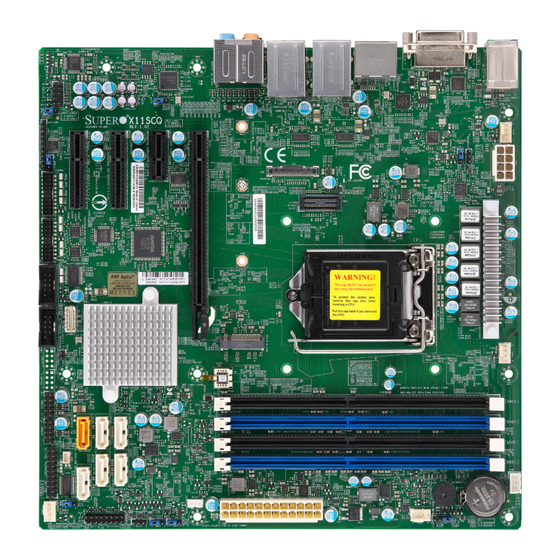
Introduction Congratulations on purchasing your computer motherboard from an acknowledged leader in the industry. Supermicro boards are designed with the utmost attention to detail to provide you with the highest standards in quality and performance. Please check that the following items have all been included with your motherboard. If anything listed here is damaged or missing, contact your retailer. - Page 9 Chapter 1: Introduction Figure 1-1. X11SCQ Motherboard Image Note: All graphics shown in this manual were based upon the latest PCB revision available at the time of publication of the manual. The motherboard you received may or may not look exactly the same as the graphics shown in this manual.
- Page 10 Super X11SCQ/-L User's Manual Figure 1-2. X11SCQ-L Motherboard Image...
- Page 11 Chapter 1: Introduction Figure 1-3. X11SCQ/-L Motherboard Layout (not drawn to scale) LAN2 SLOT7 USB8/9 (3.1 Gen2 on X11SCQ, 3.1 Gen 1 on X11SCQ-L) LAN1 JPL2 USB6/7 (3.1 Gen2 on X11SCQ, 3.1 Gen 1 on X11SCQ-L) SLOT6 KB/MOUSE DVI-D HD AUDIO...
-
Page 12: Quick Reference Table
HD AUDIO Rear Audio Ports HDMI/DP High Definition Multimedia Interface/DisplayPort I-SATA0 - I-SATA5 SATA 3.0 Ports (SATA4 and SATA5 are not available on X11SCQ-L) Speaker/Buzzer (Pins 1-4: Speaker, Pins 3-4: Buzzer) Front Control Panel Header JGP1 General Purpose I/O Header... - Page 13 USB2/3, USB4/5 Front Accessible USB 2.0 Headers USB6/7, USB8/9 Back Panel USB 3.1 Gen 2 Ports (USB 3.1 Gen 1 on X11SCQ-L) USB10/11 Front Accessible USB 3.1 Gen 2 Headers (not available on X11SCQ-L) * USB 3.1 Gen 1 is also referred to as USB 3.0...
-
Page 14: Motherboard Features
X11SCQ: Supports up to 64GB of DDR4 Non-ECC UDIMM with speeds of up to 2666MHz in four slots. • X11SCQ-L: Supports up to 32GB of DDR4 Non-ECC UDIMM with speeds of up to 2666MHz in two slots. DIMM Size •... - Page 15 Chapter 1: Introduction Motherboard Features BIOS • 256Mb SPI AMI BIOS SM Flash UEFI BIOS ® • ACPI 6.1, SMBIOS 3.1, UEFI 2.6 specification, PCI F/W 3.0, Plug-and-Play (PnP), SPI dual/quad speed support, RTC wakeup Power Management • Power button override mechanism •...
- Page 16 Super X11SCQ/-L User's Manual Figure 1-4. X11SCQ System Block Diagram 5-phase VCC IA 2-phase VCC GT SVID DDI1/Port B IMVPS DVI-D DDR4 (CHA) DIMMA1 (Black) INTEL LGA1151 DDI2/Port C HDMI2.0 LSPCON UP TO 2666MT/s DIMMA2 (Blue) DDI3/Port D (Socket-H4) DisplayPort DDR4 (CHB) DIMMB1 (Black) DIMMB2 (Blue)
- Page 17 Chapter 1: Introduction Figure 1-5. X11SCQ-L System Block Diagram 5-phase VCC IA 2-phase VCC GT SVID DDI1/Port B IMVPS DVI-D DDR4 (CHA) INTEL LGA1151 DDI2/Port C HDMI2.0 LSPCON UP TO 2666MT/s DIMMA2 (Blue) DDI3/Port D (Socket-H4) DisplayPort DDR4 (CHB) DIMMB2 (Blue)
-
Page 18: Processor And Chipset Overview
Intel Turbo Boost Technology • Intel Rapid Storage Technology • 32GB (X11SCQ-L) and 64GB (X11SCQ) DDR4 Memory Support up to 2666MHz • Advanced Graphics Displays with Audio Stream, VP8, VP9, HEVC, OpenGL, Intel Quick Sync Video Technology 1.3 Special Features This section describes the health monitoring features of the X11SCQ/-L motherboard. -
Page 19: System Health Monitoring
Chapter 1: Introduction 1.4 System Health Monitoring Onboard Voltage Monitors The onboard voltage monitor will continuously scan crucial voltage levels. Once a voltage becomes unstable, it will give a warning or send an error message to the screen. The user can adjust the voltage thresholds to define the sensitivity of the voltage monitor. -
Page 20: Acpi Features
Super X11SCQ/-L User's Manual 1.5 ACPI Features ACPI stands for Advanced Configuration and Power Interface. The ACPI specification defines a flexible and abstract hardware interface that provides a standard way to integrate power management features throughout a computer system including its hardware, operating system and application software. -
Page 21: Chapter 2 Installation
Chapter 2: Installation Chapter 2 Installation 2.1 Static-Sensitive Devices Electrostatic Discharge (ESD) can damage electronic com ponents. To avoid damaging your motherboard and your system, it is important to handle it very carefully. The following measures are generally sufficient to protect your equipment from ESD. Precautions •... -
Page 22: Motherboard Installation
Super X11SCQ/-L User's Manual 2.2 Motherboard Installation All motherboards have standard mounting holes to fit different types of chassis. Make sure that the locations of all the mounting holes for both the motherboard and the chassis match. Although a chassis may have both plastic and metal mounting fasteners, metal ones are highly recommended because they ground the motherboard to the chassis. -
Page 23: Installing The Motherboard
Chapter 2: Installation Installing the Motherboard 1. Install the I/O shield into the back of the chassis. 2. Locate the mounting holes on the motherboard. See the previous page for the location. 3. Locate the matching mounting holes on the chassis. Align the mounting holes on the motherboard against the mounting holes on the chassis. -
Page 24: Processor And Heatsink Installation
CPU socket cap is in place and none of the socket pins are bent; otherwise, contact your retailer immediately. • Refer to the Supermicro website for updates on CPU support. Installing the LGA1151 Processor 1. Press the load lever down to release the load plate from its locking position. - Page 25 Chapter 2: Installation 2. Gently lift the load lever to open the load plate. Remove the plastic protective cover. Do not touch the CPU socket contacts. 3. Locate the triangle on the CPU and CPU socket, which indicates the location of Pin 1. Holding the CPU by the edges with your thumb and index finger, align the triangle on the CPU with the triangle on the socket.
-
Page 26: Installing An Active Cpu Heatsink With Fan
Super X11SCQ/-L User's Manual 5. Close the load plate, then gently push down the load lever into its locking position. CPU properly installed Load lever locked into place Note: You can only install the CPU in one direction. Make sure it is properly inserted into the socket before closing the load plate. - Page 27 Chapter 2: Installation 6. Align the four heatsink fasteners with the mounting holes on the motherboard. Gently push down the fasteners in a diagonal order (Example: #1 and #2, then #3 and #4) into the mounting holes until you hear a click. Then lock the fasteners by turning each one 90°...
-
Page 28: Removing The Heatsink
Super X11SCQ/-L User's Manual Removing the Heatsink Note: We do not recommend that the CPU or heatsink be removed. However, if you do need to remove the heatsink, please follow the instructions below to remove the heatsink and prevent damage done to the CPU or other components. 1. -
Page 29: Memory Support And Installation
The X11SCQ motherboard supports up to 64GB of Non-ECC UDIMM with speeds of up to 2666MHz in four slots. The X11SCQ-L supports up to 32GB of Non-ECC UDIMM with speeds of up to 2666MHz in two slots. Populating the DIMM slots with a pair of memory modules of the same type, speed and size will result in interleaved memory, which improves performance. -
Page 30: Dimm Installation
Super X11SCQ/-L User's Manual DIMM Installation DVI-D AUDIO FP 1. Insert DIMM modules in the following HDMI/DP JPL2 HD AUDIO KB/MOUSE DESIGNED IN USA LAN2 LAN1 USB0/1 X11SCQ USB8/9(3.1) JPAC1 USB6/7(3.1) REV:1.01 order: DIMMA2, DIMMB2, then DIMMA1, MH12 JGP1 DIMMB1. For the system to work properly, COM5/6 JPW2 MH11... -
Page 31: Rear I/O Ports
USB0 (2.0) USB7* (3.1) CEN/LFE Out Mic In DVI-D USB6* (3.1) Surround Out LAN2 SPDIF Out * USB 3.1 Gen 2 on X11SCQ * USB 3.1 Gen 1 on X11SCQ-L * USB 3.1 Gen 1 is also referred to as USB3.0... - Page 32 Super X11SCQ/-L User's Manual DP Port DisplayPort, developed by the VESA consortium, delivers digital display and fast refresh rate. It can connect to virtually any display device using a DisplayPort adapter for devices such as VGA, DVI or HDMI. HDMI Port One HDMI (High Definition Multimedia Interface) port is on the I/O back panel.
- Page 33 HDMI/DP Chapter 2: Installation AUDIO Embedded DisplayPort LAN2 LAN1 The eDP header is used to connect an embedded display LED or LCD Panel. eDP is a USB8/9(3.1) companion standard to the DisplayPort interface designed for embedded display applications, USB6/7(3.1) including notebook PCs, tablets, netbooks and all-in-one desktop PCs. The X11SCQ/-L supports 3.3V eDP LED or LCD panel only.
- Page 34 Super X11SCQ/-L User's Manual LAN Ports There are two 1GbE LAN ports (LAN1/LAN2) on the I/O back panel. These ports accept RJ45 type cables. Refer to the table below for the pin definitions. LAN Port Pin Definition Pin# Definition Pin# Definition TX_D1+ BI_D3-...
- Page 35 There are also two USB 2.0 ports (USB0/1) and four USB 3.1 ports (USB6/7, USB8/9 - Gen 2 on X11SCQ/Gen 1 on X11SCQ-L) on the I/O back panel. USB7 and USB9 are Type-A; USB6 and USB8 are Type-C on the I/O back panel.
-
Page 36: Front Control Panel
JF1 contains header pins for various buttons and indicators that are normally located on a control panel at the front of the chassis. These connectors are designed specifically for use with Supermicro chassis. See the figure below for the descriptions of the front control panel buttons and LED indicators. - Page 37 Chapter 2: Installation Power Button The Power Button connection is located on pins 1 and 2 of JF1. Momentarily contacting both pins will power on/off the system. This button can also be configured to function as a suspend button (with a setting in the BIOS - see Chapter 4). To turn off the power in the suspend mode, press the button for at least 4 seconds.
- Page 38 Super X11SCQ/-L User's Manual Overheat (OH)/Fan Fail Connect an LED cable to OH/Fan Fail connections on pins 7 and 8 of JF1 to provide warnings for chassis overheat/fan failure. Refer to the table below for pin definitions. OH/Fan Fail Indicator OH/Fan Fail LED Pin Definitions Pin Definitions (JF1)
- Page 39 Chapter 2: Installation HDD LED The HDD LED connection is located on pins 13 and 14 of JF1. Attach a cable here to show hard drive activity status. Refer to the table below for pin definitions. HDD LED Pin Definitions (JF1) Pins Definition +3.3V...
-
Page 40: Connectors
Super X11SCQ/-L User's Manual 2.7 Connectors Main ATX Power Supply Connector The primary power supply connector (JPW1) meets the ATX SSI EPS 24-pin specification. You must also connect the 8-pin (JPW2) 12V CPU power connector to your power supply. DVI-D HDMI/DP ATX Power 24-pin Connector KB/MOUSE... - Page 41 Chapter 2: Installation TPM Header The JTPM1 header is used to connect a Trusted Platform Module (TPM)/Port 80. A TPM/Port 80 connector is a security device that supports encryption and authentication in hard drives. It allows the motherboard to deny access if the TPM associated with the hard drive is not installed in the system.
- Page 42 Super X11SCQ/-L User's Manual System Management Bus Header A System Management Bus header for additional slave devices or sensors is located at JSMB1. See the table below for pin definitions. SMBus Header Pin Definitions Pin# Definition Clock Data Ground Disk On Module Power Connector The Disk On Module (DOM) power connector at JSD1 provides 5V power to a solid-state DOM storage device connected to one of the SATA ports.
- Page 43 Chapter 2: Installation I-SATA 3.0 Ports The X11SCQ has six I-SATA 3.0 ports (I-SATA0 - I-SATA5), whereas the X11SCQ-L has four SATA 3.0 ports (I-SATA0 - I-SATA3). I-SATA0 can be used with Supermicro SuperDOMs that are yellow SATA DOM connectors with power pins built in, and do not require external power cables.
- Page 44 Super X11SCQ/-L User's Manual Speaker/Buzzer On the JD1 header, pins 1-4 are for the external speaker and pins 3-4 are for the buzzer. Speaker Connector Pin Definitions Pin Setting Definition Pins 1-4 Speaker Pins 3-4 Buzzer Chassis Intrusion A Chassis Intrusion header is located at JL1 on the motherboard. Attach the appropriate cable from the chassis to the header to inform you when the chassis is opened.
- Page 45 Chapter 2: Installation Front Accessible Audio Header A 10-pin audio header located AUDIO FP allows you to use the onboard sound for audio playback. Connect an audio cable to this header to use this feature. Refer to the table below for pin definitions.
- Page 46 Super X11SCQ/-L User's Manual High Definition Audio This motherboard features a 7.1+2 Channel High Definition Audio (HDA) codec that provides 10 DAC channels. The HD Audio connections simultaneously support multiple-streaming 7.1 sound playback with two channels of independent stereo output through the front panel stereo out for front, rear, center and subwoofer speakers.
- Page 47 Chapter 2: Installation General Purpose I/O Header The JGP1 (General Purpose Input/Output) header is a general purpose I/O expander on a pin header via the SMBus. Each pin can be configured to be an input pin or output pin in 2.54mm pitch.
- Page 48 Super X11SCQ/-L User's Manual Standby Power The Standby Power header is located at JSTBY1 on the motherboard. Refer to the table below for pin definitions. Standby Power Pin Definitions Pin# Definition +5V Standby Ground No Connection Onboard Power LED An onboard Power LED header is located at JLED1. This Power LED header is connected to the Front Control Panel located at JF1 to indicate the status of the system power.
- Page 49 The motherboard has four COM headers (COM1, COM2, COM3/4, COM5/6) that provide six serial connections. COM1 and COM2 provide one serial connection each, while COM3/4 and JPAC1 COM5/6 provide two each, utilizing Supermicro PN: CBL-CUSB-0984 (not included). COM Header (COM3/4, COM5/6) COM Header (COM1, COM2)
- Page 50 Super X11SCQ/-L User's Manual Fan Headers There are four 4-pin fan headers on the motherboard. Although these are 4-pin fan headers, pins 1-3 are backward compatible with traditional 3-pin fans. The onboard fan speeds are controlled by Thermal Management (via Hardware Monitoring) in the BIOS. When using Thermal Management setting, please use all 3-pin fans or all 4-pin fans.
-
Page 51: Jumper Settings
Chapter 2: Installation 2.8 Jumper Settings How Jumpers Work To modify the operation of the motherboard, jumpers can be used to choose between optional settings. Jumpers create shorts between two pins to change the function of the connector. Pin 1 is identified with a square solder pad on the printed circuit board. See the diagram at right for an example of jumping pins 1 and 2. - Page 52 Super X11SCQ/-L User's Manual CMOS Clear JBT1 is used to clear CMOS, which will also clear any passwords. Instead of pins, this jumper consists of contact pads to prevent accidentally clearing the contents of CMOS. To Clear CMOS 1. First power down the system and unplug the power cord(s). 2.
- Page 53 Chapter 2: Installation Force-On (ATX/AT) Use jumper JAT1 to put the motherboard into either ATX or AT mode. Setting it to AT mode enables the motherboard to power on as soon as power is supplied, even if a power loss previously occurred.
- Page 54 Super X11SCQ/-L User's Manual LAN Port Enable/Disable Use JPL1 to enable or disable LAN1, and JPL2 to enable or disable LAN2. The default setting is Enabled. LAN Port Enable/Disable Jumper Settings Jumper Setting Definition Pins 1-2 Enabled (Default) Pins 2-3 Disabled Onboard Audio Enable/Disable JPAC1 allows you to enable or disable the onboard audio support.
- Page 55 Open Disabled Onboard TPM2.0 Enable/Disable (X11SCQ only) Use JPT1 to enable or disable support for the onboard TPM 2.0 module. This jumper is not available on the X11SCQ-L. The default setting is Enabled. TPM Enable/Disable Jumper Settings Jumper Setting Definition...
-
Page 56: Led Indicators
Super X11SCQ/-L User's Manual 2.9 LED Indicators Power LED LED1 is an Onboard Power LED. When this LED is lit, it means power is present on the motherboard. In suspend mode, this LED will blink on and off. Turn off the system and unplug the power cord(s) before removing or installing components. -
Page 57: Chapter 3 Troubleshooting
Chapter 3: Troubleshooting Chapter 3 Troubleshooting 3.1 Troubleshooting Procedures Use the following procedures to troubleshoot your system. If you have followed all of the procedures below and still need assistance, refer to the ‘Technical Support Procedures’ and/ or ‘Returning Merchandise for Service’ section(s) in this chapter. Always disconnect the AC power cord before adding, changing or installing any non hot-swap hardware components. -
Page 58: No Video
Super X11SCQ/-L User's Manual No Video 1. If the power is on but you have no video, remove all the add-on cards and cables. 2. Use the speaker to determine if any beep codes exist. Refer to Appendix A for details on beep codes. -
Page 59: Losing The System's Setup Configuration
Chapter 3: Troubleshooting Losing the System's Setup Configuration 1. Make sure that you are using a high quality power supply. A poor quality power supply may cause the system to lose the CMOS setup information. Refer to Section 1.6 for details on recommended power supplies. - Page 60 Super X11SCQ/-L User's Manual 3. Using the minimum configuration for troubleshooting: Remove all unnecessary components (starting with add-on cards first), and use the minimum configuration (but with a CPU and a memory module installed) to identify the trouble areas. Refer to the steps listed in Section A above for proper troubleshooting procedures.
-
Page 61: Technical Support Procedures
Chapter 3: Troubleshooting 3.2 Technical Support Procedures Before contacting Technical Support, please take the following steps. Also, note that as a motherboard manufacturer, we do not sell directly to end-users, so it is best to first check with your distributor or reseller for troubleshooting services. They should know of any possible problem(s) with the specific system configuration that was sold to you. -
Page 62: Frequently Asked Questions
Question: What type of memory does my motherboard support? Answer: The X11SCQ supports up to 64GB of Non-ECC DDR4 UDIMM with speeds of up to 2666MHz in four slots. The X11SCQ-L supports up to 32GB of Non-ECC DDR4 UDIMM with speeds of up to 2666MHz in two slots. -
Page 63: Battery Removal And Installation
Chapter 3: Troubleshooting 3.4 Battery Removal and Installation Battery Removal To remove the onboard battery, follow the steps below: 1. Power off your system and unplug your power cable. 2. Using a tool such as a pen or a small screwdriver, push the battery lock outwards to unlock it. -
Page 64: Returning Merchandise For Service
Shipping and handling charges will be applied for all orders that must be mailed when service is complete. For faster service, RMA authorizations may be requested online at http://www.supermicro. com/RmaForm/. This warranty only covers normal consumer use and does not cover damages incurred in shipping or from failure due to the alteration, misuse, abuse or improper maintenance of products. -
Page 65: Chapter 4 Bios
Chapter 4: BIOS Chapter 4 BIOS 4.1 Introduction This chapter describes the AMIBIOS™ Setup utility for the X11SCQ/-L motherboard. The BIOS is stored on a chip and can be easily upgraded using a flash program. Note: Due to periodic changes to the BIOS, some settings may have been added or deleted and might not yet be recorded in this manual. -
Page 66: Main Setup
Note: The time is in the 24-hour format. For example, 5:30 P.M. appears as 17:30:00. The date's default value is the BIOS build date after RTC reset. Supermicro X11SCQ BIOS Version This feature displays the version of the BIOS ROM used in the system. - Page 67 Chapter 4: BIOS Memory Information Total Memory This feature displays the total size of memory available in the system.
-
Page 68: Advanced
X11SCQ/-L User's Manual 4.3 Advanced Use this menu to configure advanced settings. Warning: Take caution when changing the Advanced settings. An incorrect value, a very high DRAM frequency or an incorrect BIOS timing setting may cause the system to malfunction. When this occurs, restore to default manufacturer settings. - Page 69 Chapter 4: BIOS Wait For "F1" If Error This feature forces the system to wait until the F1 key is pressed if an error occurs. The options are Disabled and Enabled. Re-try Boot If this feature is enabled, the BIOS will automatically reboot the system from a specified boot device after its initial boot failure.
- Page 70 X11SCQ/-L User's Manual • Min CPU Speed • CPU Speed • Processor Cores • Hyper Threading Technology • • SMX/TXT • 64-bit • EIST Technology • CPU C3 state • CPU C6 state • CPU C7 state • CPU C8 state •...
- Page 71 Chapter 4: BIOS Adjacent Cache Line Prefetch The CPU prefetches the cache line for 64 bytes if this feature is set to Disabled. The CPU prefetches both cache lines for 128 bytes as comprised if this feature is set to Enabled. The options are Disabled and Enabled.
- Page 72 X11SCQ/-L User's Manual Power Limit 1 Override Select Enabled to support average power limit (PL1) override. The options are Disabled and Enabled. Power Limit 1 Use this feature to configure the value for Power Limit 1. The value is in milli watts and the step size is 125mW.
- Page 73 Chapter 4: BIOS 5-Core Ratio Limit Override This increases (multiplies) 5 clock speed in the CPU core in relation to the bus speed when five CPU core is active. Press "+" or "-" on your keyboard to change the value. Enter 33 to use the manufacture default setting.
- Page 74 X11SCQ/-L User's Manual Chipset Configuration Warning: Setting the wrong values in the sections below may cause the system to malfunction. System Agent (SA) Configuration The following information will display: • SA PCIe Code Version: 7.0.44.81 • VT-d: Supported Memory Configuration Memory Configuration •...
- Page 75 Chapter 4: BIOS Memory Scrambler Use this feature to enable or disable memory scrambler support. The options are Dis- able and Enable. MRC Fast Boot Use this feature to enable or disable fast path through the memory reference code. The options are Disable and Enable.
- Page 76 Use this feature to enable skipping of the full CD initialization. If set to Disabled, the full CD clock will initialize. The options are Enable and Disable. DMI/OPI Configuration The following DMI information will display: DMI: X4 Gen 3 (X11SCQ) or X4 Gen 2 (X11SCQ-L)
- Page 77 Chapter 4: BIOS DMI Link ASPM Control Use this feature to set the ASPM (Active State Power Management) state on the SA (System Agent) side of the DMI Link. The options are Disable, L0s, L1, and L0sL1. DMI Extended Sync Control Use this feature to enable or disable the DMI extended synchronization.
- Page 78 X11SCQ/-L User's Manual SLOT7 Slot Power Limit Scale Use this feature to select the scale used for the slot power limit value. The options are 1.0x, 0.1x, 0.01x, and 0.001x. Program PCIe ASPM After OpROM PCIe ASPM, the Active State Power Management for PCI-Express slots, is a power management protocol used to manage power consumption of serial link devices installed on PCI-E slots during a prolonged off-peak time.
- Page 79 Chapter 4: BIOS Select Owner EPOCH input type There are three Owner EPOCH modes (each EPOCH is 64 bit). The options are No Change in Owner EPOCHs, Change to New Random Owner EPOCHs, and Manual User Defined Owner EPOCHs. PRMRR Size This BIOS must reserve a contiguous region of Processor Reserved Memory (PRM) in the Porcessor Reserved Memory Range Register (PRMRR).
- Page 80 X11SCQ/-L User's Manual L1 Substates Use this feature to set the PCI Express L1 Substates. The options are Disabled, L1.1, and L1.1 & L1.2. Use this feature to enable or disable Precision Time Measurement. The options are Disabled and Enabled. Use this feature to enable or disable Downstream Port Containment.
- Page 81 Chapter 4: BIOS Change Settings This feature specifies the base I/O port address and the Interrupt Request address of a serial port specified by the user. Select Auto to allow the BIOS to automatically assign the base I/O and IRQ address. The options are Auto, (IO=3F8h; IRQ=4;), (IO=3F8h; IRQ=3, 4, 5, 6, 7, 9, 10, 11, 12;), (IO=2F8h;...
- Page 82 X11SCQ/-L User's Manual Serial Port 2 Configuration (COM4) Serial Port Select Enabled to enable the selected onboard serial port. The options are Disabled and Enabled. Device Settings This feature displays the status of a serial port specified by the user. Change Settings This feature specifies the base I/O port address and the Interrupt Request address of a serial port specified by the user.
- Page 83 Chapter 4: BIOS Change Settings This feature specifies the base I/O port address and the Interrupt Request address of a serial port specified by the user. Select Auto to allow the BIOS to automatically assign the base I/O and IRQ address. The options are Auto, (IO=258h; IRQ=7;), (IO=240h; IRQ=3, 4, 5, 6, 7, 10, 11, 12;), (IO=248h;...
- Page 84 X11SCQ/-L User's Manual Parity A parity bit can be sent along with regular data bits to detect data transmission errors. Select Even if the parity bit is set to 0, and the number of 1's in data bits is even. Select Odd if the parity bit is set to 0, and the number of 1's in data bits is odd.
- Page 85 Chapter 4: BIOS AMT SOL Console Redirection Select Enabled to use the SOL port for Console Redirection. The options are Disabled and Enabled. *If the feature above is set to Enabled, the following features are available for configuration: AMT SOL Console Redirection Settings ...
- Page 86 X11SCQ/-L User's Manual AMT SOL Flow Control Use this feature to set the flow control for Console Redirection to prevent data loss caused by buffer overflow. Send a "Stop" signal to stop sending data when the receiving buffer is full. Send a "Start" signal to start sending data when the receiving buffer is empty. The options are None and Hardware RTS/CTS.
- Page 87 Chapter 4: BIOS Serial Port for Out-of-Band Management/Windows Emergency Management Services (EMS) This submenu allows the user to configure Console Redirection settings to support Out-of- Band Serial Port management. Console Redirection Select Enabled to use a COM port selected by the user for EMS Console Redirection. The options are Disabled and Enabled.
- Page 88 X11SCQ/-L User's Manual Data Bits Use this feature to set the data transmission size for Console Redirection. The options are 7 and 8. Parity A parity bit can be sent along with regular data bits to detect data transmission errors. Select Even if the parity bit is set to 0, and the number of 1's in data bits is even.
- Page 89 Chapter 4: BIOS Serial ATA Port 0~5 This feature displays the information detected on the installed SATA drive on the particular SATA port. • Model number of drive and capacity • Software Preserve Support Serial ATA Port 0~5 Hot Plug Set this feature to Enable for hot plug support, which will allow the user to replace a SATA drive without shutting down the system.
- Page 90 X11SCQ/-L User's Manual AMT Configuration ASF support Use this feature to enable or disable Alert Standard Format support. This feature sends an alert about a potential issue when the operating system is in a sleep state. The options are Disabled and Enabled. USB Provisioning of AMT Use this feature to enable or disable USB provisioning.
- Page 91 Chapter 4: BIOS Secure Erase Configuration Secure Erase mode Select Real to securely erase a solid state drive. The options are Simulated and Real. Force Secure Erase Select Enabled to force a secure erase of the solid state drive on the next boot. The options are Disabled and Enabled.
- Page 92 X11SCQ/-L User's Manual Graphics Mode Resolution Use this feature to specify the resolution for the graphics mode. The options are Auto, 640x480, 800x600, 1024x768. ACPI Settings ACPI Sleep State Use this feature to select the ACPI Sleep State that the system will enter into when the suspend button is activated.
- Page 93 Chapter 4: BIOS USB Configuration USB Configuration • USB Module Version • USB Controllers • USB Devices Legacy USB Support Select Enabled to support onboard legacy USB devices. Select Auto to disable legacy support if there are no legacy USB devices present. Select Disable to have all USB devices available for EFI applications only.
- Page 94 X11SCQ/-L User's Manual • FAN4 • FAN1 • FAN2 • FAN3 • Vcore • • VDIMM • 5VCC • AVCC • 3.3VCC • • VBAT PCIe/PCI/PnP Configuration Video Use this feature to select the execution of the video OpROM. The options are Do not launch, UEFI, and Legacy.
- Page 95 Chapter 4: BIOS PCH SLOT6 PCI-E 3.0 X1 OPROM (PCI-E 2.0 X1 in X11SCQ-L) Use this feature to select which firmware type to be loaded for the add-on card in this slot. The options are Disabled, Legacy, and EFI. PCH SLOT5 PCI-E 3.0 X4 OPROM (PCI-E 2.0 X4 in X11SCQ-L) Use this feature to select which firmware type to be loaded for the add-on card in this slot.
- Page 96 X11SCQ/-L User's Manual Ipv4 HTTP Support Select Enabled to enable IPv4 HTTP boot support. The options are Disabled and Enabled. Ipv6 PXE Support Select Enabled to enable IPv6 PXE boot support. The options are Disabled and Enabled. Ipv6 HTTP Support Select Enabled to enable IPv6 HTTP boot support.
- Page 97 Chapter 4: BIOS SHA-1 PCR Bank Use this item to disable or enable the SHA-1 Platform Configuration Register (PCR) bank for the installed TPM device. The options are Disabled and Enabled. SHA256 PCR Bank Use this feature to disable or enable the SHA256 Platform Configuration Register (PCR) bank for the installed TPM device.
- Page 98 X11SCQ/-L User's Manual TXT support Intel TXT (Trusted Execution Technology) helps protect against software-based attacks and ensures protection, confidentiality and integrity of data stored or created on the system. Use this feature to enable or disable TXT Support. The options are Disabled and Enabled. iSCSI Configuration ...
- Page 99 Chapter 4: BIOS Intel® Ethernet Network Connection (7) I219-LM NIC Configuration Link Speed Use this feature to change the link speed and duplex for the current port. The options are Auto Negotiated, 10 Mbps Half, 10 Mbps Full, 100 Mbps Half, and 100 Mbps full. Wake On LAN Select enabled to wake the system with a magic packet.
-
Page 100: Event Logs
X11SCQ/-L User's Manual 4.4 Event Logs Use this menu to configure event log settings. Change SMBIOS Event Log Settings Enabling/Disabling Options SMBIOS Event Log Change this feature to enable or disable all features of the SMBIOS Event Logging during system boot. The options are Enabled and Disabled. Erasing Settings Erase Event Log Select Enabled to erase all error events in the SMBIOS (System Management BIOS) log... - Page 101 Chapter 4: BIOS SMBIOS Event Log Standard Settings Log System Boot Event Select Enabled to log system boot events. The options are Enabled and Disabled. MECI (Multiple Event Count Increment) Enter the increment value for the multiple event counter. Enter a number between 1 to 255. The default setting is 1.
-
Page 102: Security
X11SCQ/-L User's Manual 4.5 Security Use this menu to configure the security settings. Administrator Password Use this feature to set the administrator password which is required to enter the BIOS setup utility. The length of the password should be from three to 20 characters long. Password Check Select Setup for the system to check for a password at Setup. - Page 103 Chapter 4: BIOS • HDD Master Pwd Status Set User Password Use this feature to create a new user password for the HDD. Secure Boot System Mode Secure Boot Attempt Secure Boot Select Enable for secure boot support to ensure system security at bootup. The options are Disabled and Enabled.
- Page 104 X11SCQ/-L User's Manual Enroll Efi Image This feature allows the image to run in Secure Boot mode. Device Guard Ready Remove 'UEFI CA' from DB Use this feature to remove the Microsoft UEFI CA certificate from the database. The options are Yes and No.
- Page 105 Chapter 4: BIOS Authorized TimeStamps Update Select Yes to load a factory default dbt or No to load from a file on an external media. Append Select Yes to add the dbt from the manufacturer's defaults list to the existing dbt. Select No to load the dbt from a file.
-
Page 106: Boot
X11SCQ/-L User's Manual 4.7 Boot Use this menu to configure boot settings: Setup Prompt Timeout Use this feature to specify the length of time (the number of seconds) for the BIOS to wait before rebooting the system when the setup activation key is pressed. Enter the value of 65535 (0xFFFF) for the BIOS to wait indefinitely. - Page 107 Chapter 4: BIOS • LEGACY/UEFI/DUAL Boot Option #7 • LEGACY/UEFI/DUAL Boot Option #8 • LEGACY/UEFI/DUAL Boot Option #9 • LEGACY/UEFI/DUAL Boot Option #10 • LEGACY/UEFI/DUAL Boot Option #11 • LEGACY/UEFI/DUAL Boot Option #12 • LEGACY/UEFI/DUAL Boot Option #13 • LEGACY/UEFI/DUAL Boot Option #14 •...
- Page 108 X11SCQ/-L User's Manual Hard Disk Drive BBS Priorities This feature appears if any storage media is detected. • Boot Option # - This feature sets the system boot order of detected devices. The options are [the list of detected boot device(s)] and Disabled. ...
-
Page 109: Save & Exit
Chapter 4: BIOS 4.8 Save & Exit Use this menu to configure save and exit settings. Save Options Discard Changes and Exit Select this feature to quit the BIOS Setup without making any permanent changes to the system configuration and reboot the computer. Select Discard Changes and Exit from the Exit menu and press <Enter>. - Page 110 X11SCQ/-L User's Manual Default Options Restore Defaults To set this feature, select Restore Optimized Defaults and press <Enter>. These are factory settings designed for maximum system performance but not for maximum stability. Save as User Defaults To set this feature, select Save as User Defaults from the Exit menu and press <Enter>. This enables the user to save any changes to the BIOS setup for future use.
-
Page 111: Appendix A Bios Codes
Appendix A: BIOS Codes Appendix A BIOS Codes A.1 BIOS Error POST (Beep) Codes During the POST (Power-On Self-Test) routines, which are performed each time the system is powered on, errors may occur. Non-fatal errors are those which, in most cases, allow the system to continue the boot-up process. - Page 112 When BIOS performs the Power On Self Test, it writes checkpoint codes to I/O port 0080h. If the computer cannot complete the boot process, a diagnostic card can be attached to the computer to read I/O port 0080h (Supermicro p/n AOM-SPI80-V). For information on AMI updates, please refer to http://www.ami.com/products/.
-
Page 113: Appendix B Software Installation
The Supermicro website contains drivers and utilities for your system at https://www. supermicro.com/wftp/driver. Some of these must be installed, such as the chipset driver. After accessing the website, go into the CDR_Images (in the parent directory of the above link) and locate the ISO file for your motherboard. Download this file to create a DVD of the drivers and utilities it contains. -
Page 114: Superdoctor 5
SATA settings back to your original settings. B.2 SuperDoctor ® The Supermicro SuperDoctor 5 is a hardware monitoring program that functions in a command-line or web-based interface in Windows and Linux operating systems. The program monitors system health information such as CPU temperature, system voltages, system power consumption, fan speed, and provides alerts via email or Simple Network Management Protocol (SNMP). -
Page 115: Appendix C Standardized Warning Statements
The following statements are industry standard warnings, provided to warn the user of situations which have the potential for bodily injury. Should you have questions or experience difficulty, contact Supermicro's Technical Support department for assistance. Only certified technicians should attempt to install or configure components. - Page 116 Super X11SCQ/-L User's Manual Attention Danger d'explosion si la pile n'est pas remplacée correctement. Ne la remplacer que par une pile de type semblable ou équivalent, recommandée par le fabricant. Jeter les piles usagées conformément aux instructions du fabricant. ¡Advertencia! Existe peligro de explosión si la batería se reemplaza de manera incorrecta.
- Page 117 Appendix C: Standardized Warning Statements Product Disposal Warning! Ultimate disposal of this product should be handled according to all national laws and regulations. 製品の廃棄 この製品を廃棄処分する場合、 国の関係する全ての法律 ・ 条例に従い処理する必要があります。 警告 本产品的废弃处理应根据所有国家的法律和规章进行。 警告 本產品的廢棄處理應根據所有國家的法律和規章進行。 Warnung Die Entsorgung dieses Produkts sollte gemäß allen Bestimmungen und Gesetzen des Landes erfolgen.
-
Page 118: Appendix D Uefi Bios Recovery
Warning: Do not upgrade the BIOS unless your system has a BIOS-related issue. Flashing the wrong BIOS can cause irreparable damage to the system. In no event shall Supermicro be liable for direct, indirect, special, incidental, or consequential damages arising from a BIOS update. - Page 119 USB device or a writable CD/DVD. Note 1: If you cannot locate the "Super.ROM" file in your driver disk, visit our website www.supermicro.com to download the BIOS package. Extract the BIOS binary im- age into a USB flash device and rename it "Super.ROM" for the BIOS recovery use.
- Page 120 Super X11SCQ/-L User's Manual 3. After locating the new BIOS binary image, the system will enter the BIOS Recovery menu as shown below: Note: At this point, you may decide if you want to start the BIOS recovery. If you decide to proceed with BIOS recovery, follow the procedures below.
- Page 121 Appendix D: UEFI BIOS Recovery 5. After the BIOS recovery process is completed, press any key to reboot the system. 6. Using a different system, extract the BIOS package into a USB flash drive. 7. Press <Del> continuously during system boot to enter the BIOS Setup utility. From the top of the tool bar, select Boot to enter the submenu.
- Page 122 Super X11SCQ/-L User's Manual 8. When the UEFI Shell prompt appears, type fs# to change the device directory path. Go to the directory that contains the BIOS package you extracted earlier from Step 6. Enter flash.nsh BIOSname.### at the prompt to start the BIOS update process. Note: Do not interrupt this process until the BIOS flashing is complete.
Need help?
Do you have a question about the X11SCQ-L and is the answer not in the manual?
Questions and answers