
Related Manuals for Oregon 720-120


Summary of Contents for Oregon 720-120
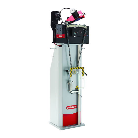
- Page 1 Original Instruction Manual Auto Chain Grinder Model 720-120 OregonProducts com 585124ab_Auto Chain Grinder_OM_720-120.indd 1 3/1/17 3:05 PM...
-
Page 2: Table Of Contents
Table of Contents 720-120 Table of Contents 5 Operation 1 Introduction 5 1 Safety during operation 1 1 Important user information 5 2 Preparing for operation 1 2 About this manual 5 2 1 Preparing the grinding wheel 1 3 Intended use... -
Page 3: Introduction
This user manual describes how to safely install, operate, and perform basic maintenance on the Oregon 720-120 Auto Chain Grinder chain sharpening machine. This manual also describes the parts of the machine, and it shows different accessories and spare parts that are available. -
Page 4: 4 Nameplate
1 Introduction 720-120 1 4 Nameplate This nameplate is placed on the Oregon 720-120 Auto Chain Grinder’s grinding head. Model: 720-120 Mfg: 2016-43 Weight: 17.5kg Input: 12V DC 12A, n : 3250min 5005667 Grinding wheel suitable for 3500min Arbor: Ø .630 In (16mm) Certified to CAN/CSA-C22.2 No. -
Page 5: Safety
720-120 2 Safety 2 1 Explanation of warning levels This section contains safety information for the Oregon 720-120 Auto Chain Grinder. This manual contains WARNINGS, CAUTIONS, and NOTES that are applicable for the safe operation of the machine. DANGER Indicates a hazard with a high level of risk which, if not avoided, will result in death or serious injury. - Page 6 WARNING To prevent mistakes when chains are sharpened, it is very important to understand how the Oregon 720-120 Auto Chain Grinder works. Read the instructions carefully before operating the machine. WARNING Always wear safety gloves, protective glasses, and any other personal protective equipment suitable for your task.
-
Page 7: 3 Signs And Symbols
CAUTION Make sure that the floor where the machine is placed is flat and level. Attach the stand to the floor with screws. 2 3 Signs and symbols See the table below for information about the signs and symbols on the Oregon 720-120 Auto Chain Grinder: Sign/Symbol Description Always wear protective glasses when using the machine. -
Page 8: Product Description
3 Product Description 3 1 Product overview The Oregon 720-120 Auto Chain Grinder is a machine that sharpens saw chains. The machine can sharpen chains (up to .404" pitch) for power saws, forestry machines, and harvesters. A pneumatic chain tensioner is attached to the stand. -
Page 9: 2 Front View
3 Product Description 720-120 3 2 Front view Part Description Grinding head Holds the grinding wheel in its correct position. Sets the number of cutters to be sharpened. See section Counter 3.6.1, “Counter” for more information. The controls starts and stops the different functions of the Control panel machine. -
Page 10: 3 Back View
3 Product Description 720-120 3 3 Back view Part Description Pitch adjustment wing Makes an approximate setting for the pitch. Grinding head cover and grinding Protects the grinding head and grinding wheel; it also wheel guard protects the user from sparks during grinding. -
Page 11: 4 Grinding Head
3 Product Description 720-120 3 4 Grinding head The grinding wheel on the grinding head sharpens the chains. The type of wheel, the top-plate angles, the settings of the grinding head, and the profiling of the grinding wheel all determine how the chain is sharpened. -
Page 12: 5 Pneumatic Chain Tensioner
3 Product Description 720-120 3 5 Pneumatic chain tensioner The purpose of the pneumatic chain tensioner is to attach and secure the chain in the correct operating position. It also keeps the chain properly tensioned during grinding. Part Description Where the tensioner slides up and down. The tensioner is Tensioner rail moved to fit chains of different lengths. -
Page 13: 6 Controls
3 Product Description 720-120 3 6 Controls Part Description Reset buttons Resets the counter. (Both buttons reset the counter.) Grinding speed knob Sets the grinding speed. ON: starts the chain feed, so that the chain moves in a Chain pusher switch forward direction. -
Page 14: 6 1 Counter
3 Product Description 720-120 3 6 1 Counter The counter consists of a display and buttons that set the number of cutters to be sharpened. Before you start the machine, use the buttons to program the number of cutting teeth to be sharpened. The machine will automatically stop after the programmed number of cutting teeth have been sharpened. -
Page 15: 8 Technical Data
• 5 7/8" x 3/16" x 5/8" (150 mm x 4.8 mm x 16 mm) Max dimensions for the Length (L) x Width (W) x Height (H): Oregon 720-120 Auto Chain Grinder 18.9" x 12.9" x 20.4" (480 mm x 330 mm x 520 mm) Dimensions, stand Length (L) x Width (W) x Height (H): 13.5"... -
Page 16: Installation
• pneumatic tensioner • converter (with 2 screws for assembly) • Oregon 720-120 Auto Chain Grinder User manual (this document) • rectangular profile stone (55 x 15 x 15 mm) and profile template • hex key, which is used to change the top-plate angle •... -
Page 17: 4 Assembling The Stand
4 4 Assembling the stand CAUTION The Oregon 720-120 Auto Chain Grinder machine must always be safely attached to the stand when it is used with a stand. When you use a bench, securely attach the machine to the bench. - Page 18 4 Installation 720-120 3 Start by placing the base piece on the floor. 5 To complete the assembly of the stand, bolt Place the front piece on top of the base the side support first to the base and then to piece by aligning the holes they have on the the front piece.
-
Page 19: 5 Assembling The Pneumatic
4 Installation 720-120 4 5 Assembling the pneumatic 3 To secure the rod, start from the top. Place the provided nut on the top of the hole and chain tensioner insert the bolt from the bottom of the rod To assemble the pneumatic chain tensioner, towards the top, and then through the nut. - Page 20 4 Installation 720-120 6 There are two air lines to be attached to 10 After the stand is assembled and secured, the pneumatic chain tensioner: one with an bolt the AC/DC converter to the back of the air fitting unit attached to the end and one stand by aligning the two holes located at without a fitting.
-
Page 21: 6 Bench-Mounting The Machine
The weight tensioner is available separately for purchase (see section 8, “Accessories and Spare Parts”). IMPORTANT Although the 720-120 machine can be used on a bench with a weight tensioner, it is strongly recommended to use it with the stand and air tensioner for the best grinding results. -
Page 22: 7 Installing The Grinding Wheel
4 Installation 720-120 4 7 Installing the grinding wheel 3 Once the grinding wheel has been verified, you’re ready to begin the install. Note: The first step in preparing the grinder for 4 Start by removing the grinding wheel shield use is installing the appropriate grinding wheel. -
Page 23: 8 Testing The Machine Before First Use
4 Installation 720-120 4 8 Testing the machine before first use 6 Next, insert the appropriate wheel onto the hub and, using moderate pressure with your 1 Make sure that all packing materials are hands, secure the wheel attachment nut to removed. -
Page 24: Operation
5 Operation 720-120 5 Operation 1 Press the power button to turn on the machine. 5 1 Safety during operation WARNING Before you install, operate, or perform maintenance on the machine, you must read the user manual. Obey the instructions in this manual to prevent injuries or damage to the equipment. -
Page 25: 2 2 Setting The Head-Tilt Angle
5 Operation 720-120 5 2 2 Setting the head-tilt angle 5 Make sure the grinding wheel edges match the shape of the chain type. Note: Read the specifications from the chain manufacturer to find out the recommended • For ceramic grinding wheels: Use the head-tilt angle for your chain. -
Page 26: 2 3 Setting The Top-Plate Angle
5 Operation 720-120 5 2 3 Setting the top-plate angle 5 If the top-plate angles are not the same (for example 26° in the right direction and 30° in Note: Read the specifications from the chain the left direction), adjust the nuts (A) a manufacturer to find out the recommended top- 1/2-turn at the time. - Page 27 5 Operation 720-120 3 Pull the chain around by hand to make sure 5 Lift the tensioner arm (there is a quick that it runs freely in the chain vise and does release function) and place the chain below not wobble.
- Page 28 5 Operation 720-120 7 Move the tensioner downward until the 9 Gently press the chain with your hand to test chain is tightly secured in its position. There the tension. The chain should not slacken. should be a gap of about 1/2" (12.7 mm)
-
Page 29: 2 5 Making The Grinding Settings
5 Operation 720-120 5 2 5 Making the grinding settings 4 Read the specifications from the chain manufacturer to find the pitch for the chain 1 Press the power button to turn on the that is to be sharpened. If you don’t know machine. - Page 30 5 Operation 720-120 7 Visually make sure that the chain pusher 10 Turn the grinding speed knob to set the stops its movement exactly above the rivet desired speed for the machine. behind the cutter, as illustrated in the image below.
- Page 31 5 Operation 720-120 13 Set the cutter top plate to equal lengths. If • Repeat steps I-II until the grinding depth the right (outer) and left (inner) cutters are is equal. not sharpened to equal lengths, follow these 15 To set the approximate grinding length, turn...
-
Page 32: 2 6 Using Skip Tooth Mode
If the chain has a joint with an irregular cutter sequence, start grinding behind it. 5 2 6 Using skip tooth mode Oregon 720-120 Auto Chain Grinder has 2 chain pusher modes: • The standard mode, used for sharpening standard chains. -
Page 33: 3 Operating The Machine
5.3. “Operate the machine.” that still need to be sharpened on the chain. CAUTION The Oregon 720-120 Auto Chain Grinder will only grind a 3/8" pitch skip-tooth type chain. No other skip tooth chains can be... - Page 34 5 Operation 720-120 • OFF to use the regular grinding mode 8 If required: Use the first, second, and third where only the cutters are sharpened. digit buttons to set the counter to the number of cutters that still need to be 3 Set the grinding wheel switch to ON to start sharpened on the chain.
- Page 35 5 Operation 720-120 13 Set the chain pusher switch to OFF. 14 Lift the tensioner arm (quick release function) and remove the chain. 15 To turn off the power to the machine, press the emergency stop button. IMPORTANT Grinding dust can interfere with the machine’s operation.
-
Page 36: Maintenance And Service
6 Maintenance and Service 720-120 6 Maintenance and Service 6 1 Safety during maintenance WARNING Make sure that the power is turned off before you install, operate, or perform maintenance on the machine. WARNING Before you install, operate, or perform maintenance on the machine, you must read the safety information in this manual. -
Page 37: 3 Changing The Grinding Wheel And Fitting The Grinding Wheel Guard
6 Maintenance and Service 720-120 6 3 Changing the grinding wheel and 3 If the grinding wheel guard is already attached, loosen the 2 screws (D) and fitting the grinding wheel guard remove the guard (C). WARNING Before a chain is sharpened,... -
Page 38: 4 Setting The Depth Gauge Height
6 Maintenance and Service 720-120 6 4 Setting the depth gauge height 6 5 Adjusting the chain lock 1 Do a sharpening test on a test chain, The chain vise needs to be fastened if the chain according to the instructions in section 7.2, is not fixed during sharpening. -
Page 39: 6 Checking And Adjusting The Wire
6 Maintenance and Service 720-120 6 6 Checking and adjusting the wire 4 Set the chain pusher switch to ON (1). When the chain pusher is in its rear position, the Note: If the wire is not correctly set, the chain vise is in its LOCKED position (2). - Page 40 6 Maintenance and Service 720-120 4 Set the top-plate angle to 25°. See section • If the wire is damaged or worn, it must 5.2.3, “Set the top-plate angle” for be replaced; see section 8.2, “List of instructions. accessories.” When it has been replaced, repeat steps 1-8.
-
Page 41: 7 Service
6 Maintenance and Service 720-120 6 7 Service WARNING The user must only perform maintenance that is described in this manual. Only approved and trained service technicians can service the machine. Note: Keep the delivery crates and packing material. Pack the machine carefully if it is moved or sent for service. -
Page 42: Troubleshooting
7 Troubleshooting 720-120 7 Troubleshooting 7 1 Troubleshooting procedure 1 Make sure that the machine has sufficient power. 2 Read section 7.3, “Issues” and section 7.4, “Troubleshooting indicators” to find a description of the issue. 3 Perform the recommended corrective procedures. -
Page 43: 3 Issues
7 Troubleshooting 720-120 7 3 Issues Issues Possible cause Corrective procedure The depth of the gullets on the The grinding wheel is not See the instructions in step 14 of left and right cutters are unevenly centered between the cutters. -
Page 44: 4 Troubleshooting Indicators
7 Troubleshooting 720-120 7 4 Troubleshooting indicators Description Possible cause Corrective action The turning motor Shows that the gear shifts. This is not an error pulse indicator indication. The turning displays a flashing motor pulse indicator is red light. purely informative. -
Page 45: Accessories And Spare Parts
8 Accessories and Spare Parts 720-120 8 Accessories and Spare Parts 8 1 Ordering information Contact your local Oregon distributor or dealer to order parts and accessories. Distributor and dealer locators can be found at OregonProducts.com 8 2 List of accessories... - Page 46 8 Accessories and Spare Parts 720-120 25 27 585124ab_Auto Chain Grinder_OM_720-120.indd 46 3/1/17 3:05 PM...
- Page 47 8 Accessories and Spare Parts 720-120 Spare Part Order Number Adjuster complete 590713 Chain lock 590690 Holder 590837 Spring 590704 Chain pusher 590703 Motor cover 590684 Turning motor 590685 Tension spring 590702 Cam curve assembly 590856 Turning motor assembly 590819...
- Page 48 8 Accessories and Spare Parts 720-120 585124ab_Auto Chain Grinder_OM_720-120.indd 48 3/1/17 3:05 PM...
- Page 49 8 Accessories and Spare Parts 720-120 Spare Part Order Number Grinding head cover 590839 590845 Grinding wheel guard 590840 Grinding wheel centering knob Grinding wheel nut 590841 Grinding wheel, see section 8.2, “List of accessories” for ordering information PDE bearing 10...
-
Page 50: 3 Converter
8 Accessories and Spare Parts 720-120 8 3 Converter Spare Part Order Number 590528 Converter 585124ab_Auto Chain Grinder_OM_720-120.indd 50 3/1/17 3:05 PM... - Page 51 8 Accessories and Spare Parts 720-120 585124ab_Auto Chain Grinder_OM_720-120.indd 51 3/1/17 3:05 PM...
-
Page 52: Grinding Angles Chart
9 Grinding Angles Chart 720-120 9 Grinding Angles Chart Code Oregon Chain Part Number Wheel Width Top-Plate Angle Head Tilt Angle Depth Gauge 25AP 1/8" 30° 55° .025" 0.65 mm 25A, 25F 90PX 1/8" 30° 55° .025" 0.65 mm 90S, 90SG... - Page 53 9 Grinding Angles Chart 720-120 Code Oregon Chain Part Number Wheel Width Top-Plate Angle Head-Tilt Angle Depth Gauge 72LPX 73-75LPX 72LGX 3/16" 25° 55° .025" 0.65 mm 73-75LGX 72-73-75JGX, JPX M72-73-75LPX 72APX, 72-73-75DPX 35° 55° .025" 0.65 mm 72-73-75RD 10°...
-
Page 54: Warranty And Service
10 Warranty and Service 720-120 10 Warranty and Service Limited Warranty At Oregon, our goal is help you get the job done right with outstanding products that perform to your full satisfaction. Oregon | Blount, Inc. warrants its products to be free from defects in materials and workmanship for two (2) years from the original date of purchase. - Page 55 585124ab_Auto Chain Grinder_OM_720-120.indd 55 3/1/17 3:06 PM...
- Page 56 Blount, Inc 4909 SE International Way Portland, Oregon 97222 USA OregonProducts com 585124 AB 02/17 585124ab_Auto Chain Grinder_OM_720-120.indd 56 3/1/17 3:06 PM...
Need help?
Do you have a question about the 720-120 and is the answer not in the manual?
Questions and answers