Table of Contents
Advertisement
Available languages
Available languages
Quick Links
Advertisement
Chapters
Table of Contents

Related Manuals for ProLights DISPLAYCOBTRWDFC


Summary of Contents for ProLights DISPLAYCOBTRWDFC
- Page 1 DISPLAYCOBTRWDFC diffUSEd LighT pRojEcToR MANUALE UTENTE USER MANUAL IT - EN...
- Page 2 Music & Lights S.r.l. si riserva ogni diritto di elaborazione in qualsiasi forma delle presenti istruzioni per l’uso. La riproduzione - anche parziale - per propri scopi commerciali è vietata. Al fine di migliorare la qualità dei prodotti, la Music&Lights S.r.l. si riserva la facoltà di modificare, in qualunque momento e senza preavviso, le specifiche menzionate nel presente manuale di istruzioni.
-
Page 3: Table Of Contents
3. 18 Temperatura 3. 19 Impostazione wireless 4 Manutenzione 4. 1 Manutenzione e pulizia del sistema ottico 4. 2 Sostituzione fusibile 4. 3 Risoluzione dei problemi Certificato di garanzia • DISPLAYCOBTRWDFC Contenuto dell'imballo: • Staffa di fissaggio • Manuale utente... -
Page 4: Sicurezza
ATTENZIONE! Prima di effettuare qualsiasi operazione con l’unità, leggere con attenzione questo manuale e conservarlo accuratamente per riferimenti futuri. Contiene informazioni importanti riguardo l’installazione, l’uso e la manutenzione dell’unità. SICUREZZA Avvertenze generali • I prodotti a cui questo manuale si riferisce sono conformi alle Direttive della Comunità Europea e per- tanto recano la sigla . -
Page 5: Informazioni Generali
INFORMAZIONI GENERALI Spedizioni e reclami Le merci sono vendute “franco nostra sede” e viaggiano sempre a rischio e pericolo del distributore/clien- te. Eventuali avarie e danni dovranno essere contestati al vettore. Ogni reclamo per imballi manomessi dovrà essere inoltrato entro 8 giorni dal ricevimento della merce. -
Page 6: Introduzione
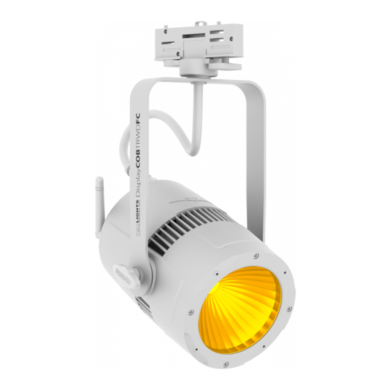
- 1 - INTRODUZIONE 1.1 DESCRIZIONE DISPLAYCOBTRWD è la versione compatta del popolare STUDIOCOB, racchiude tutte le sue migliori carat- teristiche in una struttura ultra-compatta; è ideale per installazioni commerciali e per luoghi al coperto. Grazie alla sua compattezza e alle sue caratteristiche, si candida come un nuovo standard sul mercato nel campo dei proiettori a luce diffusa. - Page 7 • Modalità colori manuali: regolazione manuale di un colore • Modalità Master/Slave con più unità collegate • Passaggio lineare “step less” dei valori sui canali DMX • Operazioni Flicker-free (da 400Hz a 25kHz, selezionabili dall’interfaccia utente) Corpo e alimentazione • Grado di isolamento: IP20...
-
Page 8: Elementi Di Comando E Di Collegamento
1.3 ELEMENTI DI COMANDO E COLLEGAMENTI Pannello Posteriore Fig.2 1. PANNELLO DI CONTROLLO con display e 4 6. GND POINT usato per la messa a terra del pulsanti per accesso e gestione delle diverse dispositivo funzioni 7. PORTAFUSIBILE: sostituire un fusibile difettoso 2. -
Page 9: Installazione
20 cm. Quindi orientare il proiettore. NOTA - Per l’installazione del proiettore DISPLAYCOBTRWDFC inserire il track adapter in un idoneo binario a quattro linee quindi ruotare la manopola di 90° per collegare l’adattatore al circuito. Far riferimento alla sequenza di operazioni mostrate in figura 3. -
Page 10: Funzioni E Impostazioni
ATTENZIONE - Assicurarsi di togliere la tensione di alimentazione prima di iniziare qualsiasi intervento di manutenzione, inserimento e sostituzione di track-adpter e dispositivi di illuminazione. 3.2 IMPOSTAZIONE BASE Il DISPLAYCOBTRWDFC dispone di un black OLED display e 4 pulsanti per accesso alle funzioni del pannel- lo di controllo (fig.4). MENU UP DOWN ENTER... -
Page 11: Struttura Menu
3.3 STRUTTURA MENU MENU (LEVEL 1) (LEVEL 2) (LEVEL 3) REMARK Auto Show Auto Show Speed Selects 1 of 4 auto programs < Auto1 > < Auto 1 > < 100 > Sets auto program speed < Auto 2 >... - Page 12 White Balance Balance White Balance Value < R=255 > < R=255 > < G=255 > < G=255 > < B=255 > < B=255 > 10 Temperature < 58 °C > 11 Wireless Setting Receive Setting Default: On < On >...
-
Page 13: Modalità Automatica
• Sull’unità MASTER selezionare il programma desiderato come indicato nel paragrafo 3.4 • Servirsi dei connettori DMX del DISPLAYCOBTRWDFC e di un cavo XLR per formare una catena di unità. In certe condizioni e lunghezze si consiglia di effettuare una terminazione come mostrato a pagina 15. -
Page 14: Modalità Dmx
DMX per il primo canale DMX. Se, per esempio, sull’unità di comando è previsto l’indirizzo 33 per comandare la funzione del primo ca- nale DMX, si deve impostare sul DISPLAYCOBTRWDFC l’indirizzo di start 33. Le altre funzioni del pannello saranno assegnate automaticamente agli indirizzi successivi. -
Page 15: Collegamenti Della Linea Dmx
3.11 COLLEGAMENTI DELLA LINEA DMX La connessione DMX è realizzata con connettori standard XLR. Utilizzare cavi schermati, 2 poli ritorti, con impedenza 120Ω e bassa capacità. Per il collegamento fare riferimento allo schema di connessione riportato di seguito: DMX - INPUT... -
Page 16: Canali Dmx
3.13 CANALI DMX 3 CANALI 8 CANALI MODE MODE FUNCTION FUNCTION Value Value 3 Ch 8 Ch DIMMER 0~100% 000 - 255 0~100% 000 - 255 GREEN 0~100% 000 - 255 0~100% 000 - 255 BLUE GREEN 0~100% 000 - 255... -
Page 17: Dimmer
3.14 DIMMER • Per entrare nella modalità dimmer e scegliere di simulare diverse curve dimming, premere il tasto MENU ripetutamente fino a quando sul display non compare Dimmer Mode, quindi premere il tasto ENTER. • Premere il tasto UP/DOWN per selezionare: Off - Dimmer 1 - Dimmer 2 - Dimmer 3. - Page 18 A questo punto collegare l’eventuale console DMX all’unità wifi per aprire la comunicazione con lo DISPLAYCOBTRWDFC. • Per effettuare il reset dell’unità selezionare invece la funzione Receive Reset attraverso i tasti UP/DOWN, quindi premere il tasto ENTER.
-
Page 19: Manutenzione
- 4 - MANUTENZIONE 4.1 MANUTENZIONE E PULIZIA DEL SISTEMA OTTICO • Durante gli interventi, assicurarsi che l’area sotto il luogo di installazione sia libera da personale non qualificato. • Spegnere l’unità, scollegare il cavo di alimentazione ed aspettare finché l’unità non si sia raffreddata. - Page 20 All rights reserved by Music & Lights S.r.l. No part of this instruction manual may be reproduced in any form or by any means for any commercial use. In order to improve the quality of products, Music&Lights S.r.l. reserves the right to modify the characteristics stated in this instruction manual at any time and without prior notice.
- Page 21 3. 16 Fixture information 3. 17 White balance 3. 18 Temperature 3. 19 Wireless setting 4 Maintenance 4. 1 Maintenance and cleaning the unit 4. 2 Fuse replacement 4. 3 Trouble shooting Warranty • DISPLAYCOBTRWDFC Packing content • Mount bracket • User manual...
-
Page 22: General Instructions
WARNING! Before carrying out any operations with the unit, carefully read this instruction manual and keep it with cure for future reference. It contains important information about the installation, usage and maintenance of the unit. SAFETY General instruction • The products referred to in this manual conform to the European Community Directives and are there- fore marked with . -
Page 23: General Information
GENERAL INFORMATION Shipments and claims The goods are sold “ex works” and always travel at the risk and danger of the distributor. Eventual dam- age will have to be claimed to the freight forwarder. Any claim for broken packs will have to be forwarded within 8 days from the reception of the goods. -
Page 24: Introduction
- 1 - INTRODUCTION 1.1 DESCRIPTION DISPLAYCOBTRWD is the compact version of the popular STUDIOCOB, keeping all its superior features in a very compact housing suitable for the installation market and indoor venues. DISPLAYCOBTRWD is designed to establish a new standard in the field of diffused light projectors, emerging from the interaction between Chip On Board technology and a new optical solution to maximize efficiency and ensure unprecedented performance in its category. - Page 25 • Flicker-free operations (from 400Hz to 25KHz selectable from the user interface) Structure and Power supply • Internal Protection: IP20 • Elegant white housing • Natural air convection cooling, no fans • Sturdy die-cast aluminum body conceived for long-time durability and demanding applications • Signal connections Input/Output: XLR 5p...
-
Page 26: Operating Elements And Connections
1.3 OPERATING ELEMENTS AND CONNECTIONS Rear panel Fig.2 1. CONTROL PANEL with display and 4 button 6. GND POINT grounding the fixture to the earth used to access the control panel functions 7. MAIN FUSE HOLDER: replace a burnt-out fuse... -
Page 27: Installation
• Adjust the projector and use the knobs. NOTE - For the installation of the DISPLAYCOBTRWDFC make sure that the ridge of the adaptor is in with the groove of the track. Turn knobs 90° to connect the adaptor to the circuit. Please see the below instruc- tions. -
Page 28: Functions And Settings
- 3 - FUNCTIONS AND SETTINGS 3.1 OPERATION To operate the projector DISPLAYCOBTRWDFC you need a system track. The track system must be installed and maintained by a suitably qualified person in compliance with latest construction and relevant legisla- tion. It is the responsibility of the installer to ensure the electrical, mechanical and thermal compatibility of the track system and the fittings. -
Page 29: Menu Structure
3.3 MENU STRUCTURE MENU (LEVEL 1) (LEVEL 2) (LEVEL 3) REMARK Auto Show Auto Show Speed Selects 1 of 4 auto programs < Auto1 > < Auto 1 > < 100 > Sets auto program speed < Auto 2 >... - Page 30 White Balance Balance White Balance Value < R=255 > < R=255 > < G=255 > < G=255 > < B=255 > < B=255 > 10 Temperature < 58 °C > 11 Wireless Setting Receive Setting Default: On < On >...
-
Page 31: Auto Show
3.4 AUTO SHOW If no DMX control signal is present at the DMX INPUT, the unit independently runs through its show pro- gramme provided that the blackout mode is switched off: • Press the button MENU so many times until the display shows Auto Show, then press the button ENTER. -
Page 32: Dmx Addressing
3.10 DMX ADDRESSING To able to operate the DISPLAYCOBTRWDFC with a light controller, adjust the DMX start address for the first a DMX channel. If e. g. address 33 on the controller is provided for controlling the function of the first DMX channel, adjust the start address 33 on the DISPLAYCOBTRWDFC. -
Page 33: Connection Of The Dmx Line
3.11 CONNECTION OF THE DMX LINE DMX connection employs standard XLR connectors. Use shielded pair-twisted cables with 120Ω imped- ance and low capacity. The following diagram shows the connection mode: DMX - INPUT DMX - OUTPUT XLR plug XLR socket... -
Page 34: Dmx Control
3.13 DMX CONTROL 3 CHANNELS 8 CHANNELS MODE MODE FUNCTION FUNCTION Value Value 3 Ch 8 Ch DIMMER 0~100% 000 - 255 0~100% 000 - 255 GREEN 0~100% 000 - 255 0~100% 000 - 255 BLUE GREEN 0~100% 000 - 255... -
Page 35: Dimmer
4. Press the MENU button to go back or to meet the waiting time to exit from the setup menu automati- cally. Fixture Hours This option shows the user the amount of hours the DISPLAYCOBTRWDFC has been in use throughout its lifetime. Select Fixture Hours. Version This option shows the user the software version currently installed in the unit. -
Page 36: Wireless Setting
Then connect any DMX console to wifi unit for to open the communication with the DISPLAYCOBTRWDFC unit. • To reset the unit press the MENU button until the display shows Receive Reset, then press the ENTER button. -
Page 37: Maintenance
- 4 - MAINTENANCE 4.1 MAINTENANCE AND CLEANING THE UNIT • Make sure the area below the installation place is free from unwanted persons during setup. • Switch off the unit, unplug the main cable and wait until the unit has cooled down. - Page 38 Note...
- Page 39 Place Stamp Here Affrancare Spett.le Music&Lights S.r.l. Via Appia Km 136.200 04020 Itri (LT) Italy "...
- Page 44 MUSIC & LIGHTS S.r.l. Via Appia, km 136,200 - 04020 Itri (LT) - ITALY Phone +39 0771 72190 - Fax +39 0771 721955 www.musiclights.it - email: info@musiclights.it ISO 9001:2008 Certified Company...
Need help?
Do you have a question about the DISPLAYCOBTRWDFC and is the answer not in the manual?
Questions and answers