Table of Contents
Advertisement
Quick Links
Advertisement
Table of Contents

Related Manuals for ProLights JETSPOT-3


Summary of Contents for ProLights JETSPOT-3
- Page 1 JETSPOT-3 MOVING HEAD USER MANUAL...
- Page 2 In order to improve the quality of products, PROLIGHTS reserves the right to modify the characteristics stated in this instruction manual at any time and without prior notice.
-
Page 3: Table Of Contents
3. 15 Construction of the DMX termination 3. 16 DMX control 3. 17 Colors and gobos 4 Maintenance 4. 1 Maintenance and cleaning the unit 4. 2 Fuse replacement 4. 3 Trouble shooting Packing content • JETSPOT-3 • Mount bracket • User manual... -
Page 4: General Instructions
JETSPOT- 3 WARNING! Before carrying out any operations with the unit, carefully read this instruction manual and keep it with cure for future reference. It contains important information about the installation, usage and maintenance of the unit. SAFETY General instruction •... -
Page 5: Introduction
JETSPOT- 3 - 1 - INTRODUCTION 1.1 DESCRIPTION JET series projectors are moving head based on a special LED optical system with a white LED source. Despite the very compact sizes, are the most efficient luminaires in its range. The compact-size structure, the rapid movements and silent operations grant this projectors to be a valu- able solution for lighting projects in limited-space environments like live stages and clubs. - Page 6 JETSPOT- 3 • RDM: RDM ready for fixture remote monitor and settings • Display: Black OLED high resolution display • Firmware Upgrade: Yes, via USB-DMX interface (UPBOX1) not included • Master/Slave: for synchronized operation of more units linked in a chain ELECTRONICS •...
-
Page 7: Operating Elements And Connections
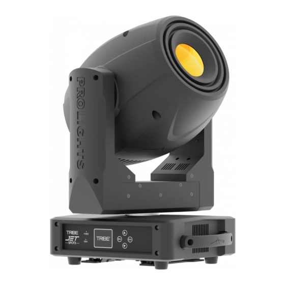
JETSPOT- 3 1.3 OPERATING ELEMENTS AND CONNECTIONS 1. MOVING HEAD 2. ROTARY ARM 3. CONTROL PANEL with LCD display and 5 button used to access the control panel functions and manage them. 4. LED INDICATOR 5. DMX IN (3-pole XLR): 1 = ground, 2 = DMX -, 3 = DMX + 6. -
Page 8: Installation
JETSPOT- 3 - 2 - INSTALLATION 2.1 MOUNTING The JET SPOT-3 may be set up on a solid and even surface. By means of the fixing facilities of the baseplate, the unit can also be mounted upside down to a cross arm. The base plate is shown in fig.3. For fixing, stable mounting clips are required. -
Page 9: Functions And Settings
Connect the supplied main cable to a socket (100-240V~/50-60Hz). The unit will run built-in program to reset all motors to their home position. Shortly after that the JETSPOT-3 is ready for operation. To switch off, disconnect the mains plug from the socket. For a more convenient operation it is recommended to connect the unit to a socket which can be switched on and off via light switch. -
Page 10: Using The Menu
JETSPOT- 3 3.3 USING THE MENU 1. Press the ENTER button to access the main menu. 2. Use the UP/DOWN button to select the menu to be used: • Connect; • Setup; • Advanced; • Information; • Stand alone; 3. Press ENTER to display the first item in the selected menu. 4. - Page 11 JETSPOT- 3 Gobo1 ð Value (000-255) for each function R-Gobo1 Gobo2 Prism Rot Focus Frost Iris ð ð ð YES/NO ADVANCED Reset Tilt Color1 Color2 Gobo1 Gobo2 Prism Focus Frost Iris ð Value (000-255) for each function ð Adjust Pan Offset Tilt Offset Color1 Offset Color2 Offset...
-
Page 12: Linking
For operation via light control unit with DMX512 protocol, is sufficient connect the controller to JET- SPOT-3. To able to operate the JETSPOT-3 with a light controller, adjust the DMX start address for the first a DMX channel. If e. g. address 33 on the controller is provided for controlling the function of the first DMX channel, adjust the start address 33 on the JETSPOT-3. -
Page 13: Fixture Settings
JETSPOT- 3 DMX Address: 33 DMX Address: 54 DMX Address: 75 DMX Address: 96 ... . DMX512 Controller Fig.6 - Example 21 DMX channels configuration 3.9 FIXTURE SETTINGS You can change the parameters for the device by following these steps: MOVEMENT •... -
Page 14: Advanced
JETSPOT- 3 • Press UP / DOWN to scroll through the menu, and then select one of the following settings for the dis- play and press the ENTER key to display it. - Back Light - Backlight display Auto Off. This feature allows you to automatically turn off the backlight after a specified time that you can set using the arrow buttons. -
Page 15: Fixture Information
JETSPOT- 3 • Press the UP/DOWN button to scroll the menu, select the Advanced icon, then press the ENTER button to enter the next menu. • Press the UP/DOWN button to scroll through the menu, select Reset and press the ENTER button to enter the next menu. -
Page 16: Operation In Automatic Mode
JETSPOT- 3 Manual settings like adjusting the DMX starting address are no longer needed. RDM is integrated in DMX without influencing the connections. The RDM-data is transmitted via the standard XLR-poles 1 and 2 so new DMX-cables are not necessary. RDM ready and conventional DMX devices can be operated in one DMX line. If DMX splitters are used and RDM control is to be used, these splitters must support RDM. -
Page 17: Connection Of The Dmx Line
JETSPOT- 3 3.14 CONNECTION OF THE DMX LINE DMX connection employs standard XLR connectors. Use shielded pair-twisted cables with 120Ω imped- ance and low capacity. The following diagram shows the connection mode: DMX - INPUT DMX - OUTPUT XLR plug XLR socket Pin1 : GND - Shield Pin2 : - Negative... -
Page 18: Dmx Control
JETSPOT- 3 3.16 DMX CONTROL STANDARD EXTENDED FUNCTION Value 17 ch 19 ch PAN 8 bit 000 - 255 PAN 16 bit 000 - 255 TILT8 bit 000 - 255 TILT 16 bit 000 - 255 MOVEMENT SPEED Fastest to slowest 000 - 255 SHUTTER Shutter closed... - Page 19 JETSPOT- 3 STANDARD EXTENDED FUNCTION Value 17 ch 19 ch CTO + JADE 012 - 015 JADE 016 - 019 JADE + CTB 020 - 023 024 - 027 CTB + PINK 028 - 031 PINK 032 - 035 PINK + LIGHT GREEN 036 - 039 LIGHT GREEN 040 - 043...
- Page 20 JETSPOT- 3 STANDARD EXTENDED FUNCTION Value 17 ch 19 ch Gobo 5 026 - 030 Gobo 6 031 - 035 Gobo 7 036 - 040 Shake Gobo 1 (shake from slow to fast) 041 - 055 Gobo 2 (shake from slow to fast) 056 - 070 Gobo 3 (shake from slow to fast) 071 - 085...
- Page 21 JETSPOT- 3 STANDARD EXTENDED FUNCTION Value 17 ch 19 ch PRISM Open 000 - 005 Indexing Positioning from 0° to 360° 006 - 191 Forward Spin Stop to fast 192 - 223 Reverse Spin Fast to Stop 224 - 255 FROST 0% to 100% 000 - 255...
-
Page 22: Colors And Gobos
JETSPOT- 3 3.17 COLOR AND GOBO WHEELS COLOR WHEEL 1 COLOR WHEEL 2 Open Open DARK CYAN DARK DARK MAGENT A JADE ORANGE BLUE LIGHT LIGHT YELLOW GREEN ORANGE PINK GREEN ROTATING GOBO FIXED GOBO... -
Page 23: Maintenance
JETSPOT- 3 - 4 - MAINTENANCE 4.1 MAINTENANCE AND CLEANING THE UNIT • Make sure the area below the installation place is free from unwanted persons during setup. • Switch off the unit, unplug the main cable and wait until the unit has cooled down. •... -
Page 24: Troubleshooting
JETSPOT- 3 4.3 TROUBLESHOOTING Problems Possible causes Checks and remedies No mains supply Check the power supply voltage • • Dimmer fader set to 0 Increase the value of the dimmer channels • • All color faders set to 0 Increase the value of the color channels •... - Page 25 Note...
- Page 26 Note...
- Page 27 Note...
Need help?
Do you have a question about the JETSPOT-3 and is the answer not in the manual?
Questions and answers