Table of Contents
Advertisement
Quick Links
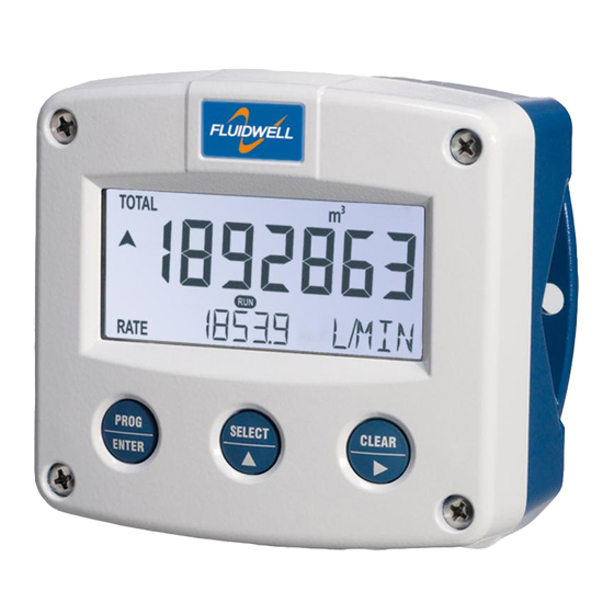
F112-P
FLOW RATE INDICATOR / TOTALIZER
with linearization, analog and pulse outputs
Signal input flowmeter: pulse, Namur and coil.
Signal outputs: (0)4-20mA / 0-10V ref. flow rate and pulse ref. total.
Options: Intrinsically safe, Modbus communication, external reset and
backlight.
F-Series - Field mounted indicators for safe and hazardous areas.
More info: www.fluidwell.com/fseries
Advertisement
Table of Contents

Related Manuals for Fluidwell F112-P


Summary of Contents for Fluidwell F112-P
- Page 1 Signal input flowmeter: pulse, Namur and coil. Signal outputs: (0)4-20mA / 0-10V ref. flow rate and pulse ref. total. Options: Intrinsically safe, Modbus communication, external reset and backlight. F-Series - Field mounted indicators for safe and hazardous areas. More info: www.fluidwell.com/fseries...
-
Page 2: Safety Instructions
▪ This unit must be installed in accordance with the EMC guidelines (Electro Magnetic Compatibility). ▪ Do connect a proper grounding to the metal enclosure as indicated if the F112-P has an incoming power line which carries a 115-230V AC. The Protective Earth (PE) wire may never be disconnected or removed. -
Page 3: About The Manual
This manual describes the standard unit as well as the available options. For additional information, please contact your supplier. A hazardous situation may occur if the F112-P is not used for the purpose it was designed for or is used incorrectly. Please carefully note the information in this manual indicated by the pictograms: A "warning !"... -
Page 4: Table Of Contents
Control panel ..........................7 2.2. Operator information and functions ................... 7 Configuration ............................9 3.1. How to programm the F112-P ....................9 3.1.2. Setup menu - Settings ......................11 3.1.3. Explanation of Setup menu 1 - Total ..................12 3.1.4. -
Page 5: Introduction
SYSTEM DESCRIPTION Functions and features The flow rate / totalizer, model F112-P is a microprocessor driven instrument designed to linearize the flowmeters flow curve and to show the flow rate, the total and the accumulated total. This product has been designed with a focus on: ▪... - Page 6 Page 6 Configuration The F112-P is designed for use in many types of applications. For that reason, a setup menu is available to program the F112-P according to your specific requirements. The setup includes several important features, such as K-Factors, engineering units, signal selection, power management (to extend battery life-time), etc.
-
Page 7: Operational
• Take careful notice of the "Safety rules, instructions and precautionary measures" in the front of this manual. This chapter describes the daily use of the F112-P. This instruction is meant for users / operators. 2.1. CONTROL PANEL The control panel has three keys. The available keys are: Fig. - Page 8 Page 8 Type IB: When a Normally Closed (NC) contact is used, the local clear total function is disabled and a clear total is only possible with the external reset command. ▪ Display accumulated total When the SELECT/ key is pressed, total and accumulated total are shown. The accumulated total cannot be reset.
-
Page 9: Configuration
How to enter the setup menu When the setup menu is protected by a password, the F112-P asks for a password to access the setup menu. When in the operator mode, press and hold the PROG/ENTER key for 7 seconds to access the setup menu. - Page 10 The SELECT/▲ key and the CLEAR/► key are used for navigation. The explanation assumes that you are in the submenu TOTAL. When you are: • in the first setting and you navigate to the previous setting, the F112-P goes back to the related main menu.
-
Page 11: Setup Menu - Settings
0000000; 111111.1; 22222.22; 3333.333 amount 0.001 - 9999999 COMMUNICATION speed 1200; 2400; 4800; 9600 address 1 - 247 mode bus-rtu; bus-asc; off OTHERS model F112-P software version nn:nn:nn serial no. nnnnnnn password 0000 - 9999 tag-nr 0000000 - 9999999 FW_F112P_v1901_02_EN.docx... -
Page 12: Explanation Of Setup Menu 1 - Total
Page 12 3.1.3. EXPLANATION OF SETUP MENU 1 - TOTAL This setting is used to select the engineering unit for the indication of the total, the UNIT accumulated total and the pulse output. When you change the engineering unit, you must recalculate and reprogram the K-factor for the (accumulated) total. -
Page 13: Explanation Of Setup Menu 3 - Display
When used with the internal battery option (type PB/PC), the user can expect reliable measurement over a long period of time. The F112-P has several smart power management functions to extend the battery life time significantly. Two of these functions can be set. -
Page 14: Explanation Of Setup Menu 5 - Flowmeter
Page 14 3.1.6. EXPLANATION OF SETUP MENU 5 - FLOWMETER SIGNAL With this setting the type of flowmeter output is selected. The settings with LP (low-pass) filter are used to apply a build-in noise reduction. Selections "active pulse" offer a detection level of 50% of the supply voltage. -
Page 15: Explanation Of Setup Menu 7 - Analog Output
Page 15 FREQUENCY / The frequency is shown at the bottom line of the display. The maximum M-FACTOR frequency is 9999.9 Hz. With value 0.0Hz, the M-Factor is disabled. The 61 TO 6F M-Factor (MF) is shown at the top-line of the display. The minimum value to be entered is 0.000001 and the maximum value is 9.999999. -
Page 16: Explanation Of Setup Menu 8 - Pulse Output
Page 16 TUNE-MAX The 20mA or 10V value can be tuned precisely with this setting. The initial maximum analog output value is 20mA or 10V However, this value might differ slightly due to ambient influences such as temperature for example. Before tuning the signal, make sure that the analog signal is idle (not used) for any application! After pressing PROG, the current will be about 20mA or 10V. -
Page 17: Explanation Of Setup Menu 9 - Communication (Option)
Consult Appendix C and the Modbus communication protocol description for a detailed explanation. This setting is used to set the Baudrate. SPEED This setting is used to set the communication address for the F112-P. ADDRESS This setting is used to set the Modbus transmission mode. Select OFF to disable MODE the communication. -
Page 18: Installation
When used in very cold surroundings or varying climatic conditions, inside the instrument case, take the necessary precautions against moisture. Mount the F112-P onto a solid structure to avoid vibrations. For use in Safe and Hazardous Areas (or Locations), the following conditions apply: Relative humidity: <... -
Page 19: Dimensions - Enclosure
Page 19 4.3. DIMENSIONS - ENCLOSURE Aluminum and stainless enclosures (where “H” turns to “HS” for stainless, e.g. HA → HSA): 75 mm (2.95") 112 mm (4.40") 130 mm (5.12") 12mm 12mm 30mm 30mm 24mm 24mm M20 x 1,5 6 x M12 36mm 36mm 25mm... - Page 20 Page 20 75 mm (2.95") 112 mm (4.40") 130 mm (5.12") HK back box: (flat bottom) 75 mm (2.95") 118 mm (4.65”) 25mm 25mm D=20mm D=20mm 12mm 12mm 30mm 30mm 24mm 24mm D=12mm D=16mm D=16mm D=20mm 36mm 36mm 0.12” 0.12” D=22mm (0.866") 3x D=22mm (0.866”) 29.1 mm (1.15”)
-
Page 21: Installing The Hardware
4.4.1. GENERAL INSTALLATION GUIDELINES • The F112-P that came with a power module type PM; 110V-230V AC or type PD/PF with an option OR (the relays can handle 110V-230V AC) shall be connected to the Protective Earth (PE) stud which is installed in the metal back panel. The metal front panel is connected to the Protective Earth by the mounting screws and serrated washers. -
Page 22: Protective Earth (Pe) Connections
Metal enclosure When the F112-P is supplied with a metal enclosure (aluminum or stainless steel), the enclosure must be grounded in accordance with national and local electrical codes. To ground the field mounted unit, the PE conductor must be connected to the PE stud which is located in the metal back cover, as indicated in the image below. -
Page 23: Aluminum Enclosure - Field Mounted
Do not use the terminal 00 to connect the protective earth wire, the 00 and the common ground terminals are internally connected. Be careful, to prevent damage to equipment when you connect different power supplies (sensor, PLC, etc.). Inside the Fluidwell display, the common grounds are internally connected to each other. -
Page 24: Plastic (Grp) Enclosure
Page 24 4.4.5. PLASTIC (GRP) ENCLOSURE The PE connection The F112-P in a GRP enclosure meets the requirements of class 2 (double insulated). Therefore the incoming PE wire is terminated with an insulating end cap. Type PM (110-230V AC) Type OR (8-24V AC) Type OR (8-30V DC) FW_F112P_v1901_02_EN.docx... -
Page 25: Terminal Connectors
Page 25 4.4.6. TERMINAL CONNECTORS Refer to Appendix A: Technical Specification Fig. 8: Overview of terminal connectors - Standard configuration and options 4.4.7. SENSOR SUPPLY For type PB/PC; PX; AP: There is no real sensor supply out available. Only a limited power supply is available. This power supply MAY NOT be used to supply the flowmeters electronics, converters etc. - Page 26 5. Close the F112-P. Risk of electrocution - High voltage! Make sure, all the leads to the terminals are disconnected from the F112-P and NEVER connect the mains power supply to the unit when the protection cover has been removed!
- Page 27 Page 27 Type OR: A mechanical relay output is available with this option. Max. switch power 240V 0,5A per output. (Requires power supply type PD/PF/PM). Be sure that the output frequency does not exceed 5Hz, else the relay life time will be reduced significantly. Fig.
- Page 28 Page 28 Type AB: An active 0-20mA signal proportional to the flow rate is available with this option. Max. driving capacity 1000 Ohm @ 24VDC. (Requires power supply type PD/PF/PM). Fig. 14: Terminal connections - Active 0-20mA analog output (typical) Type AF: For the Intrinsically safe floating 4-20mA signal: please read Chapter 5.
- Page 29 Fig. 18: Terminal connections - Coil signal input (typical) Pulse-signal NPN / NPN-LP: The F112-P is suitable for use with flowmeters which have a NPN output signal. For reliable pulse detection, the pulse amplitude has to go below 1.2V. Signal setting NPN-LP employs a low-pass signal noise filter, which limits the maximum input frequency (read chapter 3).
- Page 30 Pulse-signal PNP / PNP-LP: The F112-P is suitable for use with flowmeters which have a PNP output signal. 3V is offered on terminal 11 which has to be switched by the sensor to terminal 10 (SIGNAL). For a reliable pulse detection, the pulse amplitude has to go above 1.2V.
- Page 31 Page 31 NAMUR-signal: The F112-P is suitable for flowmeters with an Namur signal. The standard F112-P is not able to power the Namur sensor, as an external power supply for the sensor is required. However, a 8.2V sensor supply voltage (terminal 11) can be provided with power supply type PD, PF, PM.
-
Page 32: Intrinsically Safe Applications
Please note • Certificates, safety values, control drawing and declaration of conformity can be found in the document named: “Fluidwell F1..-..-XI - Documentation for Intrinsic safety”. • When installing this device in hazardous areas, the wiring and installation must comply with the appropriate installation standards for your industry. - Page 33 Page 33 Serial number and year of production This information can be looked-up in the setup menu: Others. Fig. 25: Example serial number (typical) Label information pulse input type – F1xx-..-..-XI (inside and outside the enclosure) Fig. 26: Label information - Intrinsically safe application (typical) FW_F112P_v1901_02_EN.docx...
-
Page 34: Terminal Connectors Intrinsically Safe Applications
3 and 4 and/or terminals 5 and 6; the maximum values for any of those circuits are those as defined for group IIB/IIIC. Terminal connectors F112-P-…-XI: For intrinsically safe applications, consult the safety values in the certificate. - Page 35 5. Close the F112-P. Risk of electrocution - High voltage! Make sure, all the leads to the terminals are disconnected from the F112-P and NEVER connect the mains power supply to the unit when the protection cover has been removed! Type PD-XI Power supply in: 16-30V DC / max.
-
Page 36: Configuration Examples
Page 36 CONFIGURATION EXAMPLES Fig. 30: F112-P-(AP)-(CT)-IB-(OT)-PC-XI - Battery powered - IIB/IIC - IIIC FW_F112P_v1901_02_EN.docx... - Page 37 Page 37 Fig. 31: F112-P-AP-(CT)-IB-OT-(PX)-XI - Output loop powered - IIB/IIC - IIIC FW_F112P_v1901_02_EN.docx...
-
Page 38: Battery Replacement Instructions
Page 38 BATTERY REPLACEMENT INSTRUCTIONS 5.4.1. SAFETY INSTRUCTIONS • Handle the battery with care. A mistreated battery can become unsafe. Unsafe batteries can cause (serious) injury to persons. • Only use batteries which are certified for use in hazardous areas. The use of standard batteries in hazardous area's is not safe and prohibited. -
Page 39: Maintenance
Repairs should only be carried out by the manufacturer or his authorized agent. 6.3. REPAIR POLICY If you have any problem with your Fluidwell product and you wish to repair it, please follow the procedure below: a. Obtain a Return Material Authorization (RMA) from your supplier or distributor Together with the RMA, you need to complete a repair form to submit detailed information about the problem. -
Page 40: Appendix A. Technical Specification
Page 40 APPENDIX A. TECHNICAL SPECIFICATION GENERAL Display Type High intensity reflective numeric and alphanumeric LCD, UV-resistant. Digits Seven 17mm (0.67") and eleven 8mm (0.31"). Various symbols and measuring units. Refresh rate User definable: 8 times/sec - 30 secs. Type ZB LCD with LED backlight. - Page 41 Page 41 Terminal connections Type: For Intrinsically safe applications, consult the safety values in the certificate. Sensor excitation Type PB / PC / PX 3V DC for low power pulse signals and 1.2V DC for coil pick-up. Type PD 1.2; 3; 8.2; 12; 24V DC - max. 50mA@24V DC Type PD-XI Intrinsically safe: Pulse signals: 1.2;...
- Page 42 Page 42 OUTPUTS Analog output Function transmitting linearized flow rate. Accuracy 10 bit. Error < 0.05% - update 10 times a second. Software function to calibrate the 4.00mA and 20.00mA levels precisely within set-up. Load max. 1 kOhm Type AA Active 4-20mA output (requires type OA + PD, PF or PM).
-
Page 43: Appendix B. Problem Solving
Page 43 APPENDIX B. PROBLEM SOLVING In this appendix, several problems are included that can occur when the F112-P is going to be installed or while it is in operation. Flowmeter does not generate pulses: Check: ▪ Signal selection; ▪... -
Page 44: Appendix C. Communication Variables
Page 44 APPENDIX C. COMMUNICATION VARIABLES General The product is fitted with the Modbus communication protocol and can be equipped with various physical interfaces like RS485 and RS232 (please see device datasheet for available options). The tables below show the various variables that can be accessed through the communication. Currently, the function codes supported are: •... - Page 45 Page 45 Setup variables REGISTER VARIABLE TYPE VALUE / REMARKS ADDRESS TOTAL REGISTERS [d] 32 40033 unit uint16 0=none 3=kg 6= USGAL [h] 0x020 4= lb 7=bbl 2= m 5=GAL [d] 33 40034 decimals uint16 0…3 [h] 0x021 [d] 34 40035 K-Factor uint32 1...9999999...
- Page 46 Page 46 REGISTER VARIABLE TYPE VALUE / REMARKS ADDRESS LINEARIZATION REGISTERS [d] 1024 41025 linearization table entry struct The linearization table is an INDEXED [h] 0x400 variable. Reading and writing the entries of the uint24 linearization tables is done by first selecting the entry through the index.
- Page 47 Page 47 REGISTER VARIABLE TYPE VALUE / REMARKS ADDRESS PULSE REGISTERS [d] 128 40129 width uint16 0…9999, (0=disabled) [h] 0x080 Representation: 0.000 – 9.999 sec [d] 133 40134 decimals uint16 0…3 [h] 0x085 [d] 130 40131 amount uint32 1...9999999 [h] 0x082 Representation: 0.001 –...
-
Page 48: Appendix D. Declaration Of Conformity
Page 48 APPENDIX D. DECLARATION OF CONFORMITY FW_F112P_v1901_02_EN.docx... -
Page 49: Index Of This Manual
Fig. 28: Terminal connections - Intrinsically safe floating 4-20mA analog output (typical) ....35 Fig. 29: Switch position voltage selection type PD-XI ................ 35 Fig. 30: F112-P-(AP)-(CT)-IB-(OT)-PC-XI - Battery powered - IIB/IIC - IIIC ........36 Fig. 31: F112-P-AP-(CT)-IB-OT-(PX)-XI - Output loop powered - IIB/IIC - IIIC ......... 37 FW_F112P_v1901_02_EN.docx... - Page 50 Page 50 LIST OF CONFIGURATION SETTINGS SETTING DEFAULT DATE : DATE : TOTAL Enter your settings here 11 unit 12 decimals 0000000 13 K-Factor 0000001 14 decimals K-Factor FLOW RATE 21 unit 22 time /min 23 decimals 0000000 24 K-Factor 0000001 25 decimals K-Factor 26 calculation...
- Page 51 ANALOG output disabled rate-min 0000000 rate-max 9999999 cut-off 0.0% tune-min 0208 tune-max 6656 filter 0 (off) PULSE width 0.000 sec decimals amount 0001000 COMMUNICATION speed 9600 address mode OTHERS model F112-P software version serial no. password 0000 tag-nr 0000000 FW_F112P_v1901_02_EN.docx...
- Page 52 Page 52 Fluidwell B.V. FW_F112P_v1901_02_EN.docx PO box 6 Voltaweg 23 Website: www.fluidwell.com 5460 AA Veghel 5466 AZ Veghel Find your nearest representative: www.fluidwell.com/representatives the Netherlands the Netherlands © 2021 Fluidwell B.V.: FW_F112P_v1901_02_EN.docx...
Need help?
Do you have a question about the F112-P and is the answer not in the manual?
Questions and answers