Advertisement
Quick Links
1.
Warnings
Connect the power supply and the display-/output device according to the safety
regulations for electrical equipment. The power supply must not exceed the specified
limits.
> Risk of injury, damage to or destruction of the sensor
Avoid shocks and impacts to the sensor. Avoid continuous exposure to dust and
spray on the sensor. Avoid exposure of sensor to aggressive materials (detergents,
cooling emulsions).
> Damage to or destruction of the sensor
Read the detailed instruction manual before operating the sensor. You will find this
manual on the provided CD or online at www.micro-epsilon.com.
2.
Notes on CE Identification
The following applies to the scanCONTROL 30xx/BL:
- EU Directive 2014/30/EU
- EU Directive 2011/65/EU, „RoHS" category 9
The sensor is designed for use in industry and satisfies the requirements.
The sensor fulfills the specifications of the EMC requirements, if the instructions in the
manual are followed.
3.
Proper Environment
- Protection class:
- Operating temperature:
- Storage temperature:
- Humidity:
4.
Scope of Delivery of scanCONTROL 30xx/BL
- 1 Sensor scanCONTROL 30xx/BL with integrated controller
- 1 Multifunction cable PCR2600/2900-5, length 5 m; for power supply, trigger and
RS422; screw connector and free cable ends
- Calibration final inspection / assembly instructions
- 2 protective caps
- scanCONTROL Sofware-CD with drivers, programs and documentation
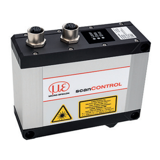
Assembly Instructions
scanCONTROL
IP 67
0 to +45 °C (+32 to +113 °F), by free circulation of air
-20 to +70 °C ( -4 to +158 °F)
5 - 95 % (non condensing)
3010/BL / 3060/BL
Advertisement

Related Manuals for MICRO-EPSILON scanCONTROL 3010/BL


Summary of Contents for MICRO-EPSILON scanCONTROL 3010/BL
- Page 1 > Damage to or destruction of the sensor Read the detailed instruction manual before operating the sensor. You will find this manual on the provided CD or online at www.micro-epsilon.com. Notes on CE Identification The following applies to the scanCONTROL 30xx/BL: - EU Directive 2014/30/EU - EU Directive 2011/65/EU, „RoHS“...
-
Page 2: Laser Safety
Laser Safety The scanCONTROL 30xx/BL sensors operate with a semiconductor laser having a wavelength of 405 nm (visible/blue). The laser operation is indicated visually by the LED on the sensor. Laser Class 2M scanCONTROL 30xx/BL sensors with a maximum laser power up to 10 mW are classi- fied in Laser Class 2M (IIM). -
Page 3: Multifunction Port
Connections, LED Displays 1 Multifunction port (Power supply, IO) 2 Ethernet port Multifunction Port Designation Sensor con- Cable color Notes nector Pin PCR2600/2900-x + 11 V - 30 V DC (rated value 24 V); max. 5 W blue +Laser on/off white available with SI option -Laser on/off... - Page 4 Trigger, Encoder, Mode Switching The switching inputs of the multifunction port can either be used for encoder-, trigger input or for loading previously stored user modes. The signal levels are switchable for all switching inputs between LLL (TTL logic) and HLL (HTL logic): - LLL level: Low 0 V …...
-
Page 5: Led Error
If the sensor is connected to a network adapter/switch that is capable of POE and if you also use the power supply of the multifunction port, these two power supplies have to be galvanically isolated. > Damage of the sensor and/or the Ethernet card! - A fixed IP address can be assigned. - Page 6 Quick Start: Commissioning, Software Install the software. Please insert the scanCONTROL Software CD in the CD-ROM device. Follow the dialog through the installa- tion process. A. Reading of installation help B. Installation of software C. Further information in the online documentation Mount the sensor according to the installation instructions.
- Page 7 First Profile Now start the scanCONTROL Configuration Tools software. Click on “Display Profiles“ in the main window. If the software shows the error message “No scanCONTROL found” in the status line, please check the Ethernet connection between scanCONTROL and PC. On the left side you can adjust the settings for your measurement task, the right side shows the profile data and information about the measurement.
- Page 8 scanCONTROL 30xx/BL with scanCONTROL Output Status voltage supply 13 14 - Power jumper contacts LINK ETHERNET ACT 1 - System LINK Data contacts Ñ System supply (OUT) 0: WBM 255: DHCP 24 V Supply via power jumper contacts System supply (In) 24 V 750-626 Power jumper...
- Page 9 Unit for Connection to an SPS Status Status 13 14 13 14 DO 2 DO 1 Function Error DO 8 DO 7 Data A1 A2 A1 A2 Data contacts contacts DO 2 DO 1 AO 1 AO 2 A3 A4 D0 4 DO 3 A5 A6...
-
Page 10: Further Information
Further Information Please refer to - the enclosed online manual - the section “Status and Error Messages“ and “Notes“ in the scanCONTROL Con- figuration Tools manual. You will find details to the separate programs in the respective instruction manuals or in the instruction manual of this sensor, Chap. - Page 12 MICRO-EPSILON Messtechnik GmbH & Co. KG Königbacher Str. 15 94496 Ortenburg / Germany, Tel. +49 (0) 85 42/1 68-0 *X9771399.02-A01* X9771399.02-A011069SWE...
Need help?
Do you have a question about the scanCONTROL 3010/BL and is the answer not in the manual?
Questions and answers