Download Print this page
MICRO-EPSILON scanCONTROL 30 Series Assembly Instructions Manual

MICRO-EPSILON scanCONTROL 30 Series Assembly Instructions Manual

Hide thumbs Also See for scanCONTROL 30 Series:

Advertisement

Quick Links

1.
Warnings
Connect the power supply and the display-/output device according to the safety
regulations for electrical equipment. The supply voltage must not exceed the specified
limits.
> Risk of injury, damage to or destruction of the sensor
Avoid shocks and impacts to the sensor. Avoid constant exposure of the sensor to dust
and splashes of water. Avoid exposure of sensor to aggressive materials (detergents,
cooling emulsions).
> Damage to or destruction of the sensor
Read the detailed operating instructions before operating the sensor.
These instructions are available online at www.micro-epsilon.com.
2.
Notes on CE Marking
The following apply to the scanCONTROL 30xx:
- EU Directive 2014/30/EU
- EU Directive 2011/65/EU
The sensor is designed for use in industrial applications.
The sensor fulfills the specifications of the EMC requirements, if the instructions in the
operating instructions are followed.
3.
Proper Environment
- Protection class:
- Temperature range:
ƒ Operation:
ƒ Storage:
- Humidity:
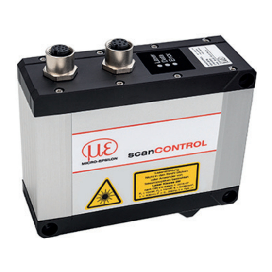
scanCONTROL 3010 / 3012
Assembly Instructions
scanCONTROL
IP67
0 ... +45 °C (+32 ... +113 °F), for free circulation of air
-20 ... +70 °C ( -4 ... +158 °F)
5 - 95 % (non-condensing)
3010 / 3012
Page 1

Advertisement

loading
Need help?

Need help?

Do you have a question about the scanCONTROL 30 Series and is the answer not in the manual?

Questions and answers

Summary of Contents for MICRO-EPSILON scanCONTROL 30 Series

  • Page 1 > Damage to or destruction of the sensor Read the detailed operating instructions before operating the sensor. These instructions are available online at www.micro-epsilon.com. Notes on CE Marking The following apply to the scanCONTROL 30xx: - EU Directive 2014/30/EU - EU Directive 2011/65/EU The sensor is designed for use in industrial applications.
  • Page 2: Laser Safety

    Laser Safety The scanCONTROL 30xx sensors operate with a semiconductor laser with a wavelength of 658 nm (visible/red). Operation of the laser is indicated visually by the LED on the sensor, see operating instructions Chap. 3.3. When operating the scan- CONTROL 30xx sensors, the relevant regulations according to IEC 60825, Part 1 of 05/2014 and the applicable accident prevention regulations must be followed.
  • Page 3 scanCONTROL LASER RADIATION DO NOT STARE INTO BEAM OR EXPOSE USERS OF TELESCOPE OPTICS CLASS 2M LASER PRODUCT IEC 60825-1: 2014 10 mW, P 10 mW; E 6 mW/cm²; λ = 658nm; F = 0...25kHz, t = 7µs...∞ COMPLIES WITH 21 CFR 1040.10 AND 1040.11 EXCEPT FOR CONFORMANCE WITH IEC 60825-1 ED.
  • Page 4 GND: galvanically isolated from In1, In2, In3, In4, RS422, laser on/off Laser on/off: input galvanically isolated from GND, In1, In2, In3, In4, RS422 In1, In2, In3, In4, RS422: inputs galvanically isolat- ed from GND and laser on/off 12-pin screw connector, view on solder side (cable) RS422, Synchronization The RS422 connection (pins 11 and 12 of the multifunction port) can be used in either of the following configurations:...
  • Page 5: Led Error

    > Damage to the sensor and/or Ethernet card! - A fixed IP address can be assigned. Use the sensorTOOL program to make specify the sensor settings described above. The program is available online at https://www.micro-epsilon.com/download/software/ sensorTOOL.exe. LED Displays LED Laser LED Data...
  • Page 6 Transmitting Measurement Results scanCONTROL 30xx offers the following options for transmitting measurement results: - Ethernet interface ƒ Modbus TCP protocol ƒ UDP protocol ƒ Analog output of measurement values (via optional 2D/3D Output Unit) ƒ Digital output of switching signals (via optional 2D/3D Output Unit) ƒ...
  • Page 7 Quick Start, Initial Operation, Software Mount the sensor according to the installation instructions. Install the software. You will find the software online on the product website of the sensor or in the download area: https://www.micro-epsilon. com/2D_3D/laser-scanner/Soft- ware/downloads/. Follow the dialog through the installation process: A.
  • Page 8 First Profile Now start the scanCONTROL Configuration Tools software. Click on Display Profiles in the main window. If the software shows the error message No scanCONTROL found in the status line, please check the Ethernet connection between scanCONTROL and the PC. On the left side you can adjust the settings for your measurement task, the right side shows the profile data and information about the measurement.
  • Page 9 2D/3D Gateway 2D/3D Gateway allows for scanCONTROL SMART sensors to be integrated into various fieldbus systems: - PROFINET - EtherNet/IP - EtherCAT All measurement results obtained from the profile evaluation carried out of a scanCONTROL SMART sensor can be transmitted to a PLC via one of these fieldbus systems.
  • Page 10 scanCONTROL 30xx with 2D/3D Output Unit for Connecting to a Status of voltage supply 13 14 - Power contacts LINK ETHERNET ACT 1 - System LINK Data contacts Ñ System supply (OUT) 0: WBM 255: DHCP 24 V Supply via power contacts System supply (In) 24 V...
  • Page 11 Status Status 13 14 13 14 DO 2 DO 1 Function Error DO 8 DO 7 Data contacts A1 A2 A1 A2 Data contacts DO 2 DO 1 AO 1 AO 2 A3 A4 DO 3 D0 4 A5 A6 A3 A4 D0 6 DO 5...
  • Page 12: Unpacking, Included In Delivery

    Configuration Tools operating instructions. You will find details about the individual programs in the respective operating instructions or in the operating instructions of this sensor, Chap. 6.2. You will find the operating instructions online at www.micro-epsilon.com. www.micro-epsilon.com MICRO-EPSILON Messtechnik GmbH & Co. KG Koenigbacher Str.