
Related Manuals for Texas Instruments Hercules TMS570LS31x


Summary of Contents for Texas Instruments Hercules TMS570LS31x
- Page 1 TMS570LS31x Hercules Development Kit (HDK) User's Guide Literature Number: SPNU509C September 2011 – Revised November 2018...
-
Page 2: Table Of Contents
........................Jumpers ....................S4, Power On Reset Switch ....................S3, System Reset Switch ....................... Operation Notices ......................Operation Notices .......................... Revision History Contents SPNU509C – September 2011 – Revised November 2018 Submit Documentation Feedback Copyright © 2011–2018, Texas Instruments Incorporated... - Page 3 Expansion Connector P3 (J11, Bottom One, TopView) ......................... 2-9. Demo LEDs ....................2-10. Other LEDs as Indicator ....................2-11. S2 DIP Switch Functions ........................2-12. Jumpers SPNU509C – September 2011 – Revised November 2018 List of Figures Submit Documentation Feedback Copyright © 2011–2018, Texas Instruments Incorporated...
-
Page 4: Preface
This document describes the board level operations of the TMS570LS31 Hercules™ Development Kit (HDK). The HDK is based on the Texas Instruments TMS570LS3137 Microcontroller. The TMS570LS31 HDK is a table top card that allows engineers and software developers to evaluate certain characteristics of the TMS570LS3137 microcontroller to determine if the microcontroller meets the designer’s application... -
Page 5: Introduction
Introduction This development kit provides a product-ready hardware and software platform for evaluating the functionality of the Texas Instruments TMS570LS31 microcontroller family. Schematics, list of materials, and PCB layout are available to ease hardware development and reduce time to market. -
Page 6: Hdk Board Block Diagram
– Type A to mini B USB cable for using on board XDS100V2 JTAG emulator – Ethernet cable – Flashlight for light sensor demo • CCS DVD Containing: – Texas Instruments’ Code Composer Studio™ Integrated Development Environments (IDE) • Hercules DVD Containing: – Hercules Safety Demos – Hardware Abstraction Layer Code Generator (HALCoGen) –... -
Page 7: Hdk Specifications
CS2 Async RAM 0x6400 0000 0x67FF FFFF CS3 Async RAM 0x6800 0000 0x7BFF FFFF CS4 Async RAM 0x8000 0000 0x87FF FFFF CS0 Sync SDRAM SPNU509C – September 2011 – Revised November 2018 Introduction Submit Documentation Feedback Copyright © 2011–2018, Texas Instruments Incorporated... -
Page 8: Power Supply
(P1), a 2.5 mm, barrel-type plug. Internally, the +12 V input is converted into +1.2 V, +3.3 V and +5.0 V using Texas Instruments swift voltage regulators and PTH power module. The +1.2 V supply is used for the MCU core while the +3.3 V supply is used for the MCU's I/O buffers and other module on the board. -
Page 9: Physical Description
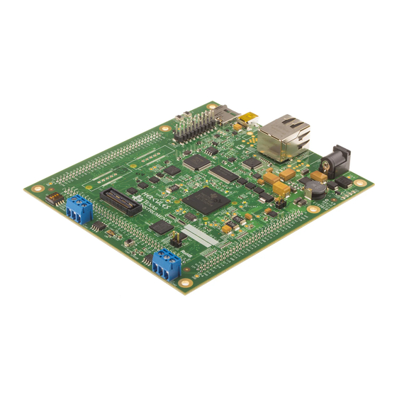
Figure 2-1 shows the layout of the TMS570LS31 HDK board. Hercules TMS570LS 3137 Figure 2-1. TMS570LS31 HDK Board, Interfaces Top Side SPNU509C – September 2011 – Revised November 2018 Physical Description Submit Documentation Feedback Copyright © 2011–2018, Texas Instruments Incorporated... -
Page 10: Connectors
40x2, 2mm EXP P3, SPI3, GIO, NHET, DCAN, LIN 19x2, mictor SD card 30x2, MIPI ETM MIPI Header 2.5mm +12 V In Physical Description SPNU509C – September 2011 – Revised November 2018 Submit Documentation Feedback Copyright © 2011–2018, Texas Instruments Incorporated... -
Page 11: 20-Pin Arm Jtag Header
J2, J3, are used to interface to the DCAN bus. The pinouts for this connector are shown in Figure 2-4. H means CAN High (CAN H), and L means CAN Low (CAN L). SPNU509C – September 2011 – Revised November 2018 Physical Description Submit Documentation Feedback Copyright © 2011–2018, Texas Instruments Incorporated... -
Page 12: J19, Mipi Etm Connector
2.2.4 J19, MIPI ETM Connector Figure 2-5 Table 2-4 show the 60 pin MIPI header. Pin 1 Figure 2-5. J19, 60 Pin MIPI ETM Header Physical Description SPNU509C – September 2011 – Revised November 2018 Submit Documentation Feedback Copyright © 2011–2018, Texas Instruments Incorporated... -
Page 13: J7, Xds100V2 Usb Jtag Interface
IDE, Code Composer Studio. The signals on this connector are shown in Table 2-5. Table 2-5. J7, XDS100V2 USB JTAG Interface Pin Number Signal Name USBVDD USBVSS SPNU509C – September 2011 – Revised November 2018 Physical Description Submit Documentation Feedback Copyright © 2011–2018, Texas Instruments Incorporated... -
Page 14: P1, +5 V To +12 V Input
A/D expansion. There are three daughter card interfaces: J9, J10, J11. These connectors are described in Table 2-6. Physical Description SPNU509C – September 2011 – Revised November 2018 Submit Documentation Feedback Copyright © 2011–2018, Texas Instruments Incorporated... -
Page 15: J9, J10, And J11 On Hdk
MibSPI5SIMO[2] MibSPI5SOMI[2] MibSPI5SIMO[3] MibSPI5SOMI[3] AD1IN[1] AD1IN[0] AD1IN[3] AD1IN[2] AD1IN[5] AD1IN[4] AD1IN[7] AD1IN[6] AD2IN[1] AD2IN[0] AD2IN[3] AD2IN[2] AD2IN[5] AD2IN[4] AD2IN[7] AD2IN[6] AGND SPNU509C – September 2011 – Revised November 2018 Physical Description Submit Documentation Feedback Copyright © 2011–2018, Texas Instruments Incorporated... -
Page 16: Expansion Connector P2 (J10, Right, Bottomview)
EMIFDATA[3] EMIFDATA[2] EMIFDATA[5] EMIFDATA[4] EMIFDATA[7] EMIFDATA[6] EMIFDATA[9] EMIFDATA[8] EMIFDATA[11] EMIFDATA[10] EMIFDATA[13] EMIFDATA[12] EMIFDATA[15] EMIFDATA[14] SPI2_SOMI EMIF_nWAIT SPI2_SIMO SPI2_CS1 SPI2_CS0 SPI2_CLK EXP_12V Physical Description SPNU509C – September 2011 – Revised November 2018 Submit Documentation Feedback Copyright © 2011–2018, Texas Instruments Incorporated... -
Page 17: Leds
LEDs DS2, DS3, DS4, and DS5 indicate the presence of the power (+1.2 V, +5 V, 3.3 V, and 12 V) s on the board. The LED functions are summarized in Table 2-9 Table 2-10. SPNU509C – September 2011 – Revised November 2018 Physical Description Submit Documentation Feedback Copyright © 2011–2018, Texas Instruments Incorporated... -
Page 18: S2 Dip Switch
“OFF” position and should remain in that position when completing the steps in this user's guide. Figure 2-8. DIP Switch Settings Physical Description SPNU509C – September 2011 – Revised November 2018 Submit Documentation Feedback Copyright © 2011–2018, Texas Instruments Incorporated... -
Page 19: Jumpers
The reset signal from window watchdog will also assert a warm reset to the MCU. The warm reset can be invoked by pushing nRST button, or by RESET signals from XDS100 CPLD, ARM JTAG SREST. SPNU509C – September 2011 – Revised November 2018 Physical Description Submit Documentation Feedback Copyright © 2011–2018, Texas Instruments Incorporated... -
Page 20: A Operation Notices
Code Composer Studio support is available via a forum at: http://community.ti.com/forums/138.aspx • Hercules MCU support is available via a forum at: http://www.ti.com/hercules-support Operation Notices SPNU509C – September 2011 – Revised November 2018 Submit Documentation Feedback Copyright © 2011–2018, Texas Instruments Incorporated... -
Page 21: Revision History
NOTE: Page numbers for previous revisions may differ from page numbers in the current version. Changes from B Revision (September 2013) to C Revision ..................Page ..............• Updated TMS570LS31 HDK Contents power supply information. SPNU509C – September 2011 – Revised November 2018 Revision History Submit Documentation Feedback Copyright © 2011–2018, Texas Instruments Incorporated... - Page 22 STANDARD TERMS FOR EVALUATION MODULES Delivery: TI delivers TI evaluation boards, kits, or modules, including any accompanying demonstration software, components, and/or documentation which may be provided together or separately (collectively, an “EVM” or “EVMs”) to the User (“User”) in accordance with the terms set forth herein.
- Page 23 FCC Interference Statement for Class B EVM devices NOTE: This equipment has been tested and found to comply with the limits for a Class B digital device, pursuant to part 15 of the FCC Rules. These limits are designed to provide reasonable protection against harmful interference in a residential installation.
- Page 24 【無線電波を送信する製品の開発キットをお使いになる際の注意事項】 開発キットの中には技術基準適合証明を受けて いないものがあります。 技術適合証明を受けていないもののご使用に際しては、電波法遵守のため、以下のいずれかの 措置を取っていただく必要がありますのでご注意ください。 1. 電波法施行規則第6条第1項第1号に基づく平成18年3月28日総務省告示第173号で定められた電波暗室等の試験設備でご使用 いただく。 2. 実験局の免許を取得後ご使用いただく。 3. 技術基準適合証明を取得後ご使用いただく。 なお、本製品は、上記の「ご使用にあたっての注意」を譲渡先、移転先に通知しない限り、譲渡、移転できないものとします。 上記を遵守頂けない場合は、電波法の罰則が適用される可能性があることをご留意ください。 日本テキサス・イ ンスツルメンツ株式会社 東京都新宿区西新宿6丁目24番1号 西新宿三井ビル 3.3.3 Notice for EVMs for Power Line Communication: Please see http://www.tij.co.jp/lsds/ti_ja/general/eStore/notice_02.page 電力線搬送波通信についての開発キットをお使いになる際の注意事項については、次のところをご覧ください。http:/ /www.tij.co.jp/lsds/ti_ja/general/eStore/notice_02.page 3.4 European Union 3.4.1 For EVMs subject to EU Directive 2014/30/EU (Electromagnetic Compatibility Directive): This is a class A product intended for use in environments other than domestic environments that are connected to a low-voltage power-supply network that supplies buildings used for domestic purposes.
- Page 25 Notwithstanding the foregoing, any judgment may be enforced in any United States or foreign court, and TI may seek injunctive relief in any United States or foreign court. Mailing Address: Texas Instruments, Post Office Box 655303, Dallas, Texas 75265 Copyright © 2018, Texas Instruments Incorporated...
- Page 26 TI products. TI’s provision of these resources does not expand or otherwise alter TI’s applicable warranties or warranty disclaimers for TI products. Mailing Address: Texas Instruments, Post Office Box 655303, Dallas, Texas 75265 Copyright © 2018, Texas Instruments Incorporated...
Need help?
Do you have a question about the Hercules TMS570LS31x and is the answer not in the manual?
Questions and answers