
Related Manuals for Texas Instruments TMS570LC43x


Summary of Contents for Texas Instruments TMS570LC43x
- Page 1 TMS570LC43x Hercules Development Kit (HDK) User's Guide Literature Number: SPNU597 May 2014...
-
Page 2: Table Of Contents
2.2.8 Daughter Card Interface ......................... LEDs ......................S2 DIP Switch ........................Jumpers ....................S4, Power On Reset Switch ....................S3, System Reset Switch ....................... Operation Notices Contents SPNU597 – May 2014 Submit Documentation Feedback Copyright © 2014, Texas Instruments Incorporated... - Page 3 Expansion Connector P3 (J11, Bottom One, TopView) ......................... 2-10. Demo LEDs ....................2-11. Other LEDs as Indicator ....................2-12. S2 DIP Switch Functions ........................2-13. Jumpers SPNU597 – May 2014 List of Figures Submit Documentation Feedback Copyright © 2014, Texas Instruments Incorporated...
-
Page 4: Preface
This document describes the board level operations of the TMS570LC43 Hercules™ Development Kit (HDK). The HDK is based on the Texas Instruments TMS570LC4357 Microcontroller. The TMS570LC43 HDK is a table top card that allows engineers and software developers to evaluate certain characteristics of the TMS570LC4357 microcontroller to determine if the microcontroller meets the designer’s application... -
Page 5: Introduction
Introduction This development kit provides a product-ready hardware and software platform for evaluating the functionality of the Texas Instruments TMS570LC43 microcontroller family. Schematics, list of materials, and PCB layout are available to ease hardware development and reduce time to market. -
Page 6: Hdk Board Block Diagram
– Type A to mini B USB cable for using on board XDS100V2 JTAG emulator – Ethernet cable – Flashlight for light sensor demo • CCS DVD Containing: – Texas Instruments’ Code Composer Studio™ Integrated Development Environments (IDE) • Hercules DVD Containing: – Hercules Safety Demos – Hardware Abstraction Layer Code Generator (HALCoGen) –... -
Page 7: Basic Operation
(P1), a 2.5 mm, barrel-type plug. Internally, the +12 V input is converted into +1.2 V, +3.3 V and +5.0 V using Texas Instruments swift voltage regulators and PTH power module. The +1.2 V supply is used for the MCU core while the +3.3 V supply is used for the MCU's I/O buffers and other module on the board. -
Page 8: Physical Description
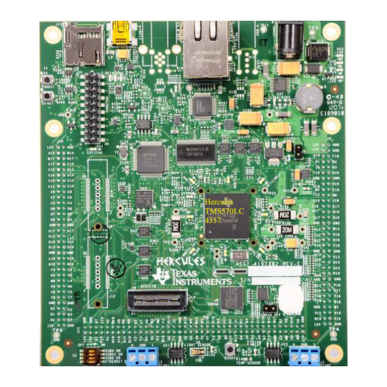
+5 V to approximately +12 V only power supply. Figure 2-1 shows the layout of the TMS570LC43 HDK board. Hercules TMS570LC 4357 Figure 2-1. TMS570LC43 HDK Board, Interfaces Top Side Physical Description SPNU597 – May 2014 Submit Documentation Feedback Copyright © 2014, Texas Instruments Incorporated... -
Page 9: Connectors
EXP P2, SPI2, EMIF, ECLK 40x2, 2mm EXP P3, SPI3, GIO, NHET, DCAN, LIN 19x2, mictor SD card 30x2, MIPI ETM MIPI Header 2.5mm +12 V In SPNU597 – May 2014 Physical Description Submit Documentation Feedback Copyright © 2014, Texas Instruments Incorporated... -
Page 10: 20-Pin Arm Jtag Header
60 Ω resistors, with a bypass capacitor tied between the resistors and to ground. The two resistors should match as close as possible. Physical Description SPNU597 – May 2014 Submit Documentation Feedback Copyright © 2014, Texas Instruments Incorporated... -
Page 11: Can Bus Termination
Connectors www.ti.com Figure 2-3. CAN Bus Termination Figure 2-4. J2, J3 CAN Bus Interface (Screw Terminal) SPNU597 – May 2014 Physical Description Submit Documentation Feedback Copyright © 2014, Texas Instruments Incorporated... -
Page 12: J19, Mipi Etm Connector
Figure 2-5. J19, 60 Pin MIPI ETM Header Table 2-4. J19, MIPI Connector Signal Mapping Signals Number Number Signals 3.3 V System reset RTCK nTRST 3.3 V Physical Description SPNU597 – May 2014 Submit Documentation Feedback Copyright © 2014, Texas Instruments Incorporated... -
Page 13: J19, Mipi Connector Signal Mapping
ETMDATA[3] ETMDATA[23] ETMDATA[4] ETMDATA[24] ETMDATA[5] ETMDATA[25] ETMDATA[6] ETMDATA[26] ETMDATA[7] ETMDATA[27] ETMDATA[8] ETMDATA[28] ETMDATA[9] ETMDATA[29] ETMDATA[10] ETMDATA[30] ETMDATA[11] ETMDATA[31] ETMDATA[12] ETMDATA[13] ETMDATA[14] ETMDATA[15] ETMDATA[16] ETMDATA[17] ETMDATA[18] SPNU597 – May 2014 Physical Description Submit Documentation Feedback Copyright © 2014, Texas Instruments Incorporated... -
Page 14: J7, Xds100V2 Usb Jtag Interface
I/O. The expansion connectors are for all major interfaces including asynchronous memory, peripherals, and A/D expansion. There are three daughter card interfaces: J9, J10, J11. These connectors are described in Table 2-7. Physical Description SPNU597 – May 2014 Submit Documentation Feedback Copyright © 2014, Texas Instruments Incorporated... -
Page 15: J9, J10, And J11 On Hdk
MibSPI5SIMO[0] MibSPI5SOMI[0] MibSPI5SIMO[1] MibSPI5SOMI[1] MibSPI5SIMO[2] MibSPI5SOMI[2] MibSPI5SIMO[3] MibSPI5SOMI[3] AD1IN[1] AD1IN[0] AD1IN[3] AD1IN[2] AD1IN[5] AD1IN[4] AD1IN[7] AD1IN[6] AD2IN[1] AD2IN[0] AD2IN[3] AD2IN[2] AD2IN[5] AD2IN[4] AD2IN[7] AD2IN[6] AGND SPNU597 – May 2014 Physical Description Submit Documentation Feedback Copyright © 2014, Texas Instruments Incorporated... -
Page 16: Expansion Connector P2 (J10, Right, Bottomview)
EMIF_BA[0] EMIF_DQMn[0] EMIFDATA[1] EMIFDATA[0] EMIFDATA[3] EMIFDATA[2] EMIFDATA[5] EMIFDATA[4] EMIFDATA[7] EMIFDATA[6] EMIFDATA[9] EMIFDATA[8] EMIFDATA[11] EMIFDATA[10] EMIFDATA[13] EMIFDATA[12] EMIFDATA[15] EMIFDATA[14] SPI2_SOMI EMIF_nWAIT SPI2_SIMO SPI2_CS1 SPI2_CS0 SPI2_CLK EXP_12V Physical Description SPNU597 – May 2014 Submit Documentation Feedback Copyright © 2014, Texas Instruments Incorporated... -
Page 17: Expansion Connector P3 (J11, Bottom One, Topview)
NHET1[17] NHET1[16] NHET1[19] NHET1[18] NHET1[21] NHET1[20] NHET1[23] NHET1[22] NHET1[25] NHET1[24] NHET1[27] NHET1[26] NHET1[29] NHET1[28] NHET1[31] NHET1[30] MibSPI3CS[3] MibSPI3CS[2] MibSPI3SIMO MibSPI3SOMI MibSPI3CS[1] MibSPI3CS[0] MibSPI3ENA MibSPI3CLK EXP_12V SPNU597 – May 2014 Physical Description Submit Documentation Feedback Copyright © 2014, Texas Instruments Incorporated... -
Page 18: Leds
“OFF” position and should remain in that position when completing the steps in this user's guide. Figure 2-8. DIP Switch Settings Physical Description SPNU597 – May 2014 Submit Documentation Feedback Copyright © 2014, Texas Instruments Incorporated... -
Page 19: Jumpers
The reset signal from window watchdog will also assert a warm reset to the MCU. The warm reset can be invoked by pushing nRST button, or by RESET signals from XDS100 CPLD, ARM JTAG SREST. SPNU597 – May 2014 Physical Description Submit Documentation Feedback Copyright © 2014, Texas Instruments Incorporated... -
Page 20: Operation Notices
URL: http://tiexpressdsp.com/index.php?title=XDS100 • Code Composer Studio support is available via a forum at: http://community.ti.com/forums/138.aspx • Hercules MCU support is available via a forum at: http://www.ti.com/hercules-support Operation Notices SPNU597 – May 2014 Submit Documentation Feedback Copyright © 2014, Texas Instruments Incorporated... - Page 21 IMPORTANT NOTICE Texas Instruments Incorporated and its subsidiaries (TI) reserve the right to make corrections, enhancements, improvements and other changes to its semiconductor products and services per JESD46, latest issue, and to discontinue any product or service per JESD48, latest issue.
Need help?
Do you have a question about the TMS570LC43x and is the answer not in the manual?
Questions and answers