Table of Contents
Advertisement
Quick Links
Advertisement
Table of Contents

Subscribe to Our Youtube Channel
Related Manuals for Texas Instruments Hercules TMS570LS31


Summary of Contents for Texas Instruments Hercules TMS570LS31
- Page 1 TMS570LS31 Hercules™ ARM® Safety MCU Development Kit (HDK) USER GUIDE...
-
Page 2: Table Of Contents
Figure 3, J2, J3 Screw Terminal Block ..............11 Figure 4, J19, 60pin MIPI ETM Header ............... 12 Figure 5, +12 Volt Input Jack ................13 Figure 6, DIP Switch Settings ................20 Texas Instruments Proprietary Information – Internal Data... - Page 3 Table 12, Expansion Connector P3 (J11, Bottom One, TopView) ...... 17 Table 13, Demo LEDs ..................18 Table 14, Other LEDs as Indicator ..............19 Table 15, S2 DIP Switch Functions ..............20 Table 16, Jumpers ....................20 Texas Instruments Proprietary Information – Internal Data...
- Page 4 About This Manual This document describes the board level operations of the TMS570LS31 Hercules Development Kit (HDK). The HDK is based on the Texas Instruments TMS570LS3137 337 BGA Microcontroller. The TMS570LS31 HDK is a table top card that allows engineers and software developers to evaluate certain characteristics of the TMS570LS31 microcontroller to determine if the microcontroller meets the designer’s application requirements as well as begin...
-
Page 5: Introduction
1. Introduction This development kit provides a product-ready hardware and software platform for evaluating the functionality of the Texas Instruments TMS570LS31x and TMS570LS21x microcontroller family. Schematics, list of materials, and PCB layout are available to ease hardware development and reduce time to market. -
Page 6: Hdk Board Block Diagram
Type A to mini B USB cable for using on board XDS100V2 JTAG emulator Category-5 Ethernet cable Flashlight for light sensor demo DVD Containing Texas Instruments’ Code Composer Studio™ IDE (CCS) nowFlash™ Flash Programming Tools nowECC™ ECC Tool HALCoGen GUI-based device configuration and driver examples Texas Instruments Proprietary Information – Internal Data... -
Page 7: Hdk Specifications
0x0840 0000 0x0843 FFFF RAM-ECC 0x6000 0000 0x63FF FFFF CS2 Async RAM 0x6400 0000 0x67FF FFFF CS3 Async RAM 0x6800 0000 0x7BFF FFFF CS4 Async RAM 0x8000 0000 0x87FF FFFF CS0 Sync SDRAM Texas Instruments Proprietary Information – Internal Data... -
Page 8: Power Supply
(P1), a 2.5 mm, barrel-type plug. Internally, the +12V input is converted into +1.2V, +3.3V and +5.0V using Texas Instruments swift voltage regulators and PTH power module. The +1.2V supply is used for the MCU core while the +3.3V supply is used for the MCU's I/O buffers and other module on the... -
Page 9: Physical Description
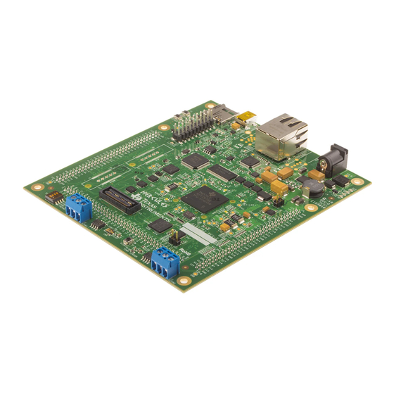
Figure 2, TMS570LS31 HDK Board, Interfaces Top Side 2.2 Connectors The HDK board has twenty nine (29) interfaces to various peripherals. These interfaces are described in the following sections. Table 3, Connectors on HDK Board Texas Instruments Proprietary Information – Internal Data... -
Page 10: 20Pin Arm Jtag Header
The several configurations of the TMS570LS31 series integrate an Ethernet MAC on chip. Please consult the family datasheets for availability. This interface is routed to the on board PHY via CBT switches. The board uses a DP83640 PHY. Texas Instruments Proprietary Information – Internal Data... -
Page 11: Can Interface
DCAN bus. The pinouts for this connector are shown in the figure below. H means CAN High (CAN H), and L means CAN Low (CAN L). Figure 3, J2, J3 Screw Terminal Block 2.2.4 J19, MIPI ETM Connector The following figure and table show the 60 pin MIPI header. Texas Instruments Proprietary Information – Internal Data... - Page 12 27 28 ETMDATA[24] ETMDATA[5] 29 30 ETMDATA[25] ETMDATA[6] 31 32 ETMDATA[26] ETMDATA[7] 33 34 ETMDATA[27] ETMDATA[8] 35 36 ETMDATA[28] ETMDATA[9] 37 38 ETMDATA[29] ETMDATA[10] 39 40 ETMDATA[30] ETMDATA[11] 41 42 ETMDATA[31] ETMDATA[12] 43 44 Texas Instruments Proprietary Information – Internal Data...
-
Page 13: J7, Xds100V2 Usb Jtag Interface
Connector P1 is the input power connector. This connector brings in +12 volts to the HDK Board. This is a 2.5 mm. jack. The figure below shows this connector as viewed from the card edge. Figure 5, +12 Volt Input Jack Texas Instruments Proprietary Information – Internal Data... -
Page 14: Sci Interface
J9, J10, J11. These connectors are described in the table below. Table 8, Expansion Connector P2 (J10, Right, TopView) Signal Name Pin# Pin# Signal Name EXP_12V EXP_12V MibSPI1ENA MibSPI1CLK MibSPI1CS[1] MibSPI1CS[0] MibSPI1CS[3] MibSPI1CS[2] MibSPI1SIMO MibSPI1SOMI Texas Instruments Proprietary Information – Internal Data... - Page 15 AD2IN[4] AD2IN[7] AD2IN[6] AGND AD1IN[9] AD1IN[8] AD1IN[11] AD1IN[10] AD1IN[13] AD1IN[12] AD1IN[15] AD1IN[14] POR_RSTn ADREFHI ADREFLO AD1EVT AD2EVT EXP_12V Table 9, Expansion Connector P1 (J9, Left, TopView) Signal Name Pin# Pin# Signal Name EXP_12V Texas Instruments Proprietary Information – Internal Data...
- Page 16 EMIF_ADDR[4] EMIF_ADDR[3] EMIF_ADDR[2] EMIF_ADDR[1] EMIF_ADDR[0] EMIF_Wen EMIF_CS[3] EMIF_Oen EMIF_CS[2] EMIF_BA[1] EMIF_DQMn[1] EMIF_BA[0] EMIF_DQMn[0] EMIFDATA[1] EMIFDATA[0] EMIFDATA[3] EMIFDATA[2] EMIFDATA[5] EMIFDATA[4] EMIFDATA[7] EMIFDATA[6] EMIFDATA[9] EMIFDATA[8] EMIFDATA[11] EMIFDATA[10] EMIFDATA[13] EMIFDATA[12] EMIFDATA[15] EMIFDATA[14] SPI2_SOMI EMIF_nWAIT SPI2_SIMO SPI2_CS1 Texas Instruments Proprietary Information – Internal Data...
- Page 17 FRAYTX2 FRAYTXEN1 FRAYTXEN2 GIOA[1] GIOA[0] GIOA[3] GIOA[2] GIOA[5] GIOA[4] GIOA[7] GIOA[6] GIOB[1] GIOB[0] GIOB[3] GIOB[2] GIOB[5] GIOB[4] GIOB[7] GIOB[6] NHET1[1] NHET1[0] NHET1[3] NHET1[2] NHET1[5] NHET1[4] NHET1[7] NHET1[6] NHET1[9] NHET1[8] NHET1[11] NHET1[10] NHET1[13] NHET1[12] Texas Instruments Proprietary Information – Internal Data...
-
Page 18: Leds
3.3V, and 12V) s on the board. The LED functions are summarized in the table below. Table 11, Demo LEDs LED# Location Signals Color Left Top NHET1[17] White NHET1[31] White Right Top NHET1[0] White Right Bottom NHET1[25] White Texas Instruments Proprietary Information – Internal Data... - Page 19 Table 12, Other LEDs as Indicator Color nERROR XDS100V2 SCI RX Blue XDS100V2 SCI TX Blue XDS100V2 PWRENn Blue JTAG TDI Blue Ethernet Speed Blue ARM JTAG Plugin Blue VCC_1V2 Blue VCC_5V Blue VCC_3V3 Blue VCC_12V Blue Texas Instruments Proprietary Information – Internal Data...
-
Page 20: S2 Dip Switch
HDK board has two (2) jumpers which are used to enable/disable the on-board SDRAM and select 5V or 3.3V ADC as such: Table 14, Jumpers Jumper # 5V ADC 3.3V ADC SDRAM on SDRAM Off 2.6 S4, Power On Reset Switch Texas Instruments Proprietary Information – Internal Data... -
Page 21: S3, System Reset Switch
Switch S3 to assert a warm reset the TMS570LS31 device. However, a warm reset does not reset any on-chip test or emulation logic. The reset signal from the windowed watchdog will also assert a warm reset to MCU. Texas Instruments Proprietary Information – Internal Data... -
Page 22: Schematics
TMS570LS31 HDK User Guide Appendix A Schematics This appendix contains the schematics for the TMS570LS31 HDK board. Texas Instruments Proprietary Information – Internal Data... - Page 23 TMS570LS31 HDK User Guide Texas Instruments Proprietary Information – Internal Data...
- Page 24 TMS570LS31 HDK User Guide Texas Instruments Proprietary Information – Internal Data...
- Page 25 TMS570LS31 HDK User Guide Texas Instruments Proprietary Information – Internal Data...
- Page 26 TMS570LS31 HDK User Guide Texas Instruments Proprietary Information – Internal Data...
- Page 27 TMS570LS31 HDK User Guide Texas Instruments Proprietary Information – Internal Data...
- Page 28 TMS570LS31 HDK User Guide Texas Instruments Proprietary Information – Internal Data...
- Page 29 TMS570LS31 HDK User Guide Texas Instruments Proprietary Information – Internal Data...
- Page 30 TMS570LS31 HDK User Guide Texas Instruments Proprietary Information – Internal Data...
- Page 31 TMS570LS31 HDK User Guide Texas Instruments Proprietary Information – Internal Data...
- Page 32 TMS570LS31 HDK User Guide Texas Instruments Proprietary Information – Internal Data...
- Page 33 TMS570LS31 HDK User Guide Texas Instruments Proprietary Information – Internal Data...
- Page 34 TMS570LS31 HDK User Guide Texas Instruments Proprietary Information – Internal Data...
- Page 35 TMS570LS31 HDK User Guide Texas Instruments Proprietary Information – Internal Data...
-
Page 36: Operation Notices
XDS100 USB wiki on the TI web site. The URL for this site is: http://tiexpressdsp.com/index.php?title=XDS100 Code Composer Studio support is available via a forum at: http://community.ti.com/forums/138.aspx 3. Hercules Processor and Kit Support is available at: http://www.ti.com/hercules-support Texas Instruments Proprietary Information – Internal Data... - Page 37 IMPORTANT NOTICE Texas Instruments Incorporated and its subsidiaries (TI) reserve the right to make corrections, modifications, enhancements, improvements, and other changes to its products and services at any time and to discontinue any product or service without notice. Customers should obtain the latest relevant information before placing orders and should verify that such information is current and complete.
Need help?
Do you have a question about the Hercules TMS570LS31 and is the answer not in the manual?
Questions and answers