
Related Manuals for Allied Telesis AlliedWare Plus x220 Series


Summary of Contents for Allied Telesis AlliedWare Plus x220 Series
- Page 1 x220 Series Gigabit Ethernet Switches AlliedWare Plus™ AT-x220-28GS AT-x220-52GT AT-x220-52GP Installation Guide 613-002649 Rev. B...
- Page 2 Allied Telesis, Inc. has been advised of, known, or should have known, the...
- Page 3 Electrical Safety and Emissions Standards This product meets the following standards. U.S. Federal Communications Commission Radiated Energy Note: This equipment has been tested and found to comply with the limits for a Class A digital device pursuant to Part 15 of FCC Rules.
- Page 4 Translated Safety Statements Important: Safety statements that have the symbol are translated into multiple languages in the Translated Safety Statements document at www.alliedtelesis.com/library. Remarque: Les consignes de sécurité portant le symbole sont traduites dans plusieurs langues dans le document Translated Safety Statements, disponible à l'adresse www.alliedtelesis.com/ library...
-
Page 5: Table Of Contents
Contents Preface ....................................11 Document Conventions ...............................12 Contacting Allied Telesis ..............................13 Chapter 1: Overview ................................ 15 Front and Rear Panels ................................16 Management Panel ................................18 Features ....................................19 x220 Models .................................19 10/100/1000Mbps Twisted Pair Ports ..........................19 100Mbps or 1Gbps SFP Transceiver Ports........................19 Power Over Ethernet ..............................20 LEDs.....................................20... - Page 6 Contents Chapter 3: Installing the Switch on a Table or Desktop ....................47 Chapter 4: Installing the Switch in an Equipment Rack ....................51 Beginning the Installation..............................52 Required Items ................................52 Switch Orientations in the Equipment Rack......................... 52 Removing the Bumper Feet ..............................54 Installing the Switch ................................
- Page 7 Figures Figure 1: Front Panels of the x220 Series Switches......................16 Figure 2: Back Panels ................................17 Figure 3: Management Panel ...............................18 Figure 4: LEDs for the Twisted Pair Ports on the AT-x220-52GT Switch ................23 Figure 5: LEDs for the Twisted Pair Ports on the AT-x220-52GP Switch................24 Figure 6: SFP Transceiver Ports LEDs..........................29 Figure 7: Fault and Power LEDs............................31 Figure 8: eco-friendly Button ..............................32...
- Page 8 Figures...
- Page 9 Tables Table 1: Basic Features ...............................19 Table 2: LEDS for the Twisted Pair Ports on the AT-x220-52GT Switch ................23 Table 3: LEDs for the Twisted Pair Ports on the AT-x220-52GP Switch ................25 Table 4: IEEE Powered Device Classes ..........................26 Table 5: LEDS for the SFP Transceiver Ports ........................29 Table 6: Fault and Power LEDS ............................31 Table 7: USB LED ................................33 Table 8: PORT Parameter Format ............................36...
- Page 10 Tables...
-
Page 11: Preface
Preface This guide contains the installation instructions for the x220 Series of Gigabit Ethernet switches. This preface contains the following sections: “Document Conventions” on page 12 “Contacting Allied Telesis” on page 13... -
Page 12: Document Conventions
Preface Document Conventions This document uses the following conventions: Note Notes provide additional information. Caution Cautions inform you that performing or omitting a specific action may result in equipment damage or loss of data. Warning Warnings inform you that performing or omitting a specific action may result in bodily injury. -
Page 13: Contacting Allied Telesis
Series Installation Guide Contacting Allied Telesis If you need assistance with this product, you can contact Allied Telesis technical support by going to the Support & Services section of the Allied Telesis web site at www.alliedtelesis.com/support. You can find links for the following services on this page: ... - Page 14 Preface...
-
Page 15: Chapter 1: Overview
Chapter 1 Overview This chapter contains the following sections: “Front and Rear Panels” on page 16 “Management Panel” on page 18 “Features” on page 19 “10/100/1000Mbps Twisted Pair Ports” on page 22 “Power Over Ethernet on the AT-x220-52GP Switch” on page 26 ... -
Page 16: Front And Rear Panels
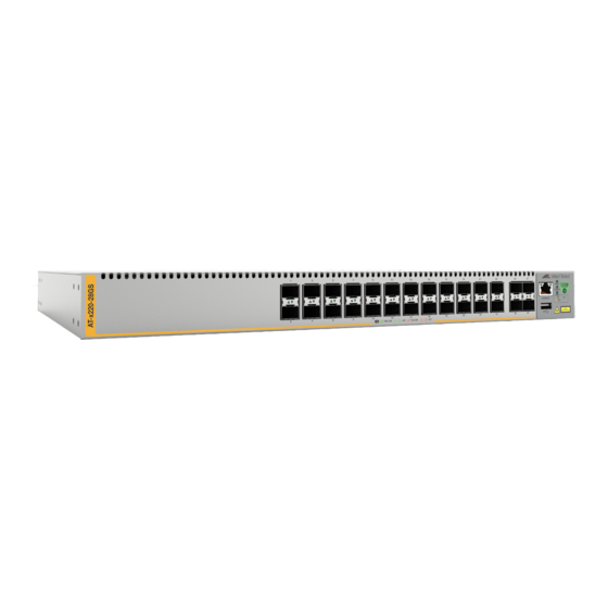
Chapter 1: Overview Front and Rear Panels The front panels on the x220 Gigabit Ethernet Switches are shown in Figure 1. AT-x220-28GS Switch 28 100Mbps or 1Gbps Management SFP Transceiver Ports Panel AT-x220-52GT Switch Four 100Mbps or 48 10/100/1000Mbps Twisted Management 1Gbps SFP Panel... -
Page 17: Figure 2: Back Panels
x220 Series Installation Guide AT-x220-28GS or AT-x220-52GT Switch AC Power Supply Connector AT-x220-52GP AC Power Supply Connector Figure 2. Back Panels... -
Page 18: Management Panel
Chapter 1: Overview Management Panel Figure 3 identifies the components on the management panel. Console Management System LEDs Port eco-friendly Button USB Port Figure 3. Management Panel... -
Page 19: Features
Single-port, BiDi fiber optic transceivers AT-SPTX 1Gbps (1000Base-TX) transceiver with RJ-45 connector for twisted pair cable SFP transceivers must be purchased separately. For a list of supported transceivers, refer to the product data sheet on the Allied Telesis web site. -
Page 20: Power Over Ethernet
Chapter 1: Overview Power Over Here are the basic features of PoE and PoE+ on the twisted pair ports on the AT-x220-52GP Switch: Ethernet Supported on all forty eight twisted pair ports Supports PoE (15.4 watts maximum) and PoE+ (30 watts maximum) powered devices ... -
Page 21: Management Methods
x220 Series Installation Guide Restore configuration files from flash drive to switches whose settings have been lost or corrupted, or to configure replacement units. Update the AlliedWare Plus Management Software. Management Here are the methods for managing the switches: Methods ... -
Page 22: 10/100/1000Mbps Twisted Pair Ports
Chapter 1: Overview 10/100/1000Mbps Twisted Pair Ports The following sections describe the twisted pair ports on the AT-x220- 52GT and AT-x220-52GP Switches. Connector Type The twisted pair ports have 8-pin RJ-45 connectors. The ports use four pins at 10 or 100Mbps and all eight pins at 1000Mbps. The pin assignments are listed in “RJ-45 Twisted Pair Port Pinouts”... -
Page 23: Automatic Mdix Detection
x220 Series Installation Guide Automatic MDIX The 10/100/1000Mbps twisted-pair ports are IEEE 802.3ab compliant. They feature automatic MDIX detection when operating at 10 or 100Mbps. Detection (Automatic MDIX detection does not apply to 1000Mbps.) The switch automatically configures the ports to MDI or MDI-X depending on the wiring configurations of the end nodes. -
Page 24: Figure 5: Leds For The Twisted Pair Ports On The At-X220-52Gp Switch
Chapter 1: Overview Table 2. LEDS for the Twisted Pair Ports on the AT-x220-52GT Switch State Description Flashing Amber The port is transmitting or receiving packets at 10 or 100Mbps. Possible causes of this state are listed here: - The port has not established a link with another network device. -
Page 25: Table 3: Leds For The Twisted Pair Ports On The At-X220-52Gp Switch
x220 Series Installation Guide Table 3. LEDs for the Twisted Pair Ports on the AT-x220-52GP Switch State Description Speed/Activity LED Solid Green The port has established a 1Gbps link to a network device. Flashing Green The port is transmitting or receiving packets at 1Gbps. -
Page 26: Power Over Ethernet On The At-X220-52Gp Switch
Chapter 1: Overview Power Over Ethernet on the AT-x220-52GP Switch The AT-x220-52GP Switch features PoE on all forty eight 10/100/ 1000Mbps ports. With PoE, the switch can supply DC power to network devices over the same twisted pair cables that carry the network traffic. PoE can make it easier to install networks. -
Page 27: Power Budget
x220 Series Installation Guide Table 4. IEEE Powered Device Classes (Continued) Maximum Power Class Output from a Switch PD Power Range Port 7.0W 3.84W to 6.49W 15.4W 6.49W to 12.95W 30.0W 12.95W to 25.5W Power Budget The AT-x220-52GP Switch has a DC power budget of 740W. This is the total maximum amount of power that the switch can supply to the powered devices on its twisted pair ports. -
Page 28: Wiring Implementation
Chapter 1: Overview power only if all the ports set to the Critical level are already receiving power. If there is not enough power to support all of the ports set to the High priority level, power is provided to the ports based on port number, in ascending order. -
Page 29: Sfp Transceiver Ports
1000Base-TX transceivers with RJ-45 connectors for twisted pair cable SFP transceivers are purchased separately. For a list of supported transceivers, refer to the product data sheet on the Allied Telesis web site. LEDs Each transceiver port has one LED. Refer to Figure 6. - Page 30 Chapter 1: Overview Table 5. LEDS for the SFP Transceiver Ports (Continued) State Description Possible causes of this state are listed here: - The SFP transceiver port is empty. - The SFP transceiver has not established a link with another network device.
-
Page 31: Fault And Power Leds
x220 Series Installation Guide Fault and Power LEDs The Fault and Power LEDs are shown in Figure 7. Fault and Power LEDs Figure 7. Fault and Power LEDs Note The USB LED is described in “USB Port” on page 33. The states of the LEDs are described in Table 6. -
Page 32: Eco-Friendly Button
Chapter 1: Overview eco-friendly Button The eco-friendly button on the front panel of the switch is used to toggle the port LEDs on or off. Refer to Figure 8. You can turn off the LEDs to conserve electricity when you are not using them to monitor the device. You can also toggle the LEDs with the ECOFRIENDLY LED and NO ECOFRIENDLY LED commands in the Global Configuration mode of the command line interface of the AlliedWare Plus management software. -
Page 33: Usb Port
x220 Series Installation Guide USB Port You can use the USB port on the management panel for the following functions: Store configuration files on flash drives. Restore configuration files to switches whose settings have been lost or corrupted. ... -
Page 34: Console Port
Chapter 1: Overview Console Port The Console port is an RS232 serial management port. You use the port to access the AlliedWare Plus management software on the switch to configure the feature settings or monitor status or statistics. This type of management uses the management cable included with the unit. -
Page 35: Power Supply And Fan
x220 Series Installation Guide Power Supply and Fan The switches come with one pre-installed power supply. Refer to “Technical Specifications” on page 89 for the input voltage ranges. A power cord and retaining clip are included with the switch. Warning Power cord is used as a disconnection device. -
Page 36: Specifying Ports In The Command Line Interface
Chapter 1: Overview Specifying Ports in the Command Line Interface The individual ports on the switches are specified with the PORT parameter in the command line interface of the AlliedWare Plus management software. The format of the parameter is shown in Figure 10. port1 Stack ID Module ID... -
Page 37: Chapter 2: Beginning The Installation
Chapter 2 Beginning the Installation The chapter contains the following sections: “Reviewing Safety Precautions” on page 38 “Installation Options” on page 42 “Choosing a Site for the Switch” on page 43 “Unpacking the Switch” on page 44... -
Page 38: Reviewing Safety Precautions
Chapter 2: Beginning the Installation Reviewing Safety Precautions Please review the following safety precautions before beginning the installation procedure. Note Safety statements with the symbol are translated into multiple languages in the Translated Safety Statements document at www.alliedtelesis.com/library. Warning Class 1 Laser product. - Page 39 x220 Series Installation Guide Warning Power cord is used as a disconnection device. To de-energize equipment, disconnect the power cord. E3 Warning Class I Equipment. This equipment must be earthed. The power plug must be connected to a properly wired earth ground socket outlet.
- Page 40 E25 Warning The chassis may be heavy and awkward to lift. Allied Telesis recommends that you get assistance when mounting the chassis in an equipment rack. E28 Note Use dedicated power circuits or power conditioners to supply reliable electrical power to the device.
- Page 41 x220 Series Installation Guide Caution Installation of the equipment in a rack should be such that the amount of air flow required for safe operation of the equipment is not compromised. E36 Warning Reliable earthing of rack-mounted equipment should be maintained. Particular attention should be given to supply connections other than direct connections to the branch circuits (e.g., use of power strips).
-
Page 42: Installation Options
Chapter 2: Beginning the Installation Installation Options Figure 11 illustrates the three installation options. Tabletop Standard 19-inch equipment rack Wood or concrete wall Figure 11. Installation Options... -
Page 43: Choosing A Site For The Switch
x220 Series Installation Guide Choosing a Site for the Switch Observe these requirements when planning the installation of the switch. Before installing the switch in an equipment rack, check that the rack is safely secured so that it will not tip over. Devices in a rack should be installed starting at the bottom of the rack, with the heavier devices near the bottom. -
Page 44: Unpacking The Switch
Chapter 2: Beginning the Installation Unpacking the Switch Figure 12 shows the shipping box. Accessory Kit Figure 12. x220 Switch Shipping Box Note You should retain the original packaging material in case you need to return the unit to Allied Telesis. -
Page 45: Figure 13: Accessory Kit For The At-X220-28Gs Switch
x220 Series Installation Guide Figure 13 lists the items in the accessory kit for the AT-x220-28GS Switch. One 2m (6.6 ft) local management cable with RJ-45 (8P8C) and DB-9 (D- sub 9-pin) connectors. One regional AC power cords Two wall/equipment rack brackets Eight screws for attaching the wall/ equipment rack brackets to the... -
Page 46: Figure 14: Accessory Kit For The At-X220-52Gt And At-X220-52Gp Switches
Chapter 2: Beginning the Installation Figure 14 lists the items in the accessory kit for the AT-x220-52GT and AT- x220-52GP Switches. One 2m (6.6 ft) local management cable with RJ-45 (8P8C) and DB-9 (D- sub 9-pin) connectors. One regional AC power cords Four wall/equipment rack brackets Sixteen screws for attaching the wall/... -
Page 47: Chapter 3: Installing The Switch On A Table Or Desktop
Chapter 3 Installing the Switch on a Table or Desktop This chapter contains the instructions for installing the switch on a table or desktop. Warning Switches should not be stacked on a table or desktop. They could present a physical safety hazard if you need to move or replace switches. -
Page 48: Figure 16: Inset The Rivet Housing Into The Bumper Foot
Chapter 3: Installing the Switch on a Table or Desktop 5. Install the bumper feet as follows: a. Inset a rivet housing into a bumper foot. Refer to Figure 16. Figure 16. Inset the Rivet Housing into the Bumper Foot b. -
Page 49: Figure 18: Inserting The Rivet Into The Bumper Foot
x220 Series Installation Guide Figure 18. Inserting the Rivet into the Bumper Foot d. Repeat this step to install the remaining bumper feet. 6. Turn the switch over and place it on a flat, secure desk or table, leaving ample space around it for ventilation. 7. - Page 50 Chapter 3: Installing the Switch on a Table or Desktop...
-
Page 51: Chapter 4: Installing The Switch In An Equipment Rack
Chapter 4 Installing the Switch in an Equipment Rack This chapter contains the instructions for installing the switch in a standard 19-inch equipment rack. The procedures in this chapter are listed here: “Beginning the Installation” on page 52 “Removing the Bumper Feet”... -
Page 52: Beginning The Installation
Chapter 4: Installing the Switch in an Equipment Rack Beginning the Installation This chapter contains the procedure for installing the switch in a standard 19-inch equipment rack, with the brackets included with the unit. Required Items The following items are required to install the switch in an equipment rack: ... -
Page 53: Figure 20: X220 Switch Orientations In An Equipment Rack
x220 Series Installation Guide Figure 20. x220 Switch Orientations in an Equipment Rack... -
Page 54: Removing The Bumper Feet
Chapter 4: Installing the Switch in an Equipment Rack Removing the Bumper Feet The bumper feet included with the switch should not be used when installing the device in an equipment rack. If they are already installed, perform the following procedure to remove them: 1. -
Page 55: Installing The Switch
Please review the installation guidelines in “Choosing a Site for the Switch” on page 43 before installing the switch. Caution The chassis may be heavy and awkward to lift. Allied Telesis recommends that you get assistance when mounting the chassis in an equipment rack. E28... -
Page 56: Figure 23: Installing The Switch In An Equipment Rack
Chapter 4: Installing the Switch in an Equipment Rack Figure 23. Installing the Switch in an Equipment Rack 5. Go to Chapter 6, “Cabling the Networking Ports and Powering On the Switch” on page 71. -
Page 57: Chapter 5: Installing The Switch On A Wall
Chapter 5 Installing the Switch on a Wall The procedures in this chapter are listed here: “Switch Orientations on a Wall” on page 58 “Installation Guidelines” on page 59 “Plywood Base” on page 61 “Installing a Plywood Base” on page 63 ... -
Page 58: Switch Orientations On A Wall
Chapter 5: Installing the Switch on a Wall Switch Orientations on a Wall You can install the switch on a wall with the front panel on the left or right, as shown in Figure 24. Do not install it with the front panel on the top or bottom. -
Page 59: Installation Guidelines
x220 Series Installation Guide Installation Guidelines Here are the guidelines to installing the switch on a wall: You can install the switch on a wall with wooden studs or on a concrete wall. If you are installing the switch on a wall with wooden studs, you should use a plywood base to support the switch. - Page 60 Chapter 5: Installing the Switch on a Wall Stud finder for a wooden wall, capable of identifying the middle of wall studs and hot electrical wiring (not provided) Drill and 1/4” carbide drill bit for a concrete wall (not provided) ...
-
Page 61: Plywood Base
Series Installation Guide Plywood Base If you are installing the switch on a wall with wooden studs, Allied Telesis recommends using a plywood base for the device. (A plywood base is not required for a concrete wall.) Refer to Figure 25. -
Page 62: Figure 26: Steps To Installing The Switch With A Plywood Base
Chapter 5: Installing the Switch on a Wall between the studs in your wall is different than the industry standard. You should install the plywood base on the wall and then install the switch on the base. Refer to Figure 26. Wall Studs Plywood Base... -
Page 63: Installing A Plywood Base
x220 Series Installation Guide Installing a Plywood Base A plywood base is recommended when installing the switch on a wall that has wooden studs. Refer to “Plywood Base” on page 61. Consult a qualified building contractor for installation instructions for the plywood base. -
Page 64: Installing The Switch On A Plywood Base
This procedure assumes that the plywood base for the switch is already installed on the wall. Please review “Reviewing Safety Precautions” on page 38 and “Choosing a Site for the Switch” on page 43 before performing this procedure. Allied Telesis recommends a minimum of two people for this procedure. Warning The device is heavy. -
Page 65: Figure 28: Bracket Positions For Installing The At-X220-52Gt Or At-X220-52Gp Switch On A Wall
x220 Series Installation Guide 3. For the AT-x220-52GT or AT-x220-52GP Switch, install the four wall/ equipment rack brackets to the sides of the unit with the sixteen M4x6mm screws included with the device. Refer to Figure 28 on page Figure 28. Bracket Positions for Installing the AT-x220-52GT or AT-x220- 52GP Switch on a Wall 4. -
Page 66: Figure 29: Securing The Switch To The Plywood Base
Chapter 5: Installing the Switch on a Wall Two screws for the Four screws for the AT-x220-28GS Switch AT-x220-52GT or AT-x220- 52GP Switch Figure 29. Securing the Switch to the Plywood Base 5. Go to Chapter 6, “Cabling the Networking Ports and Powering On the Switch”... -
Page 67: Installing The Switch On A Concrete Wall
x220 Series Installation Guide Installing the Switch on a Concrete Wall This section contains the instructions for installing the switch on a concrete wall. Please review the information in the following sections before performing the procedure: “Switch Orientations on a Wall” on page 58 ... -
Page 68: Figure 30: Marking The Locations Of The Bracket Holes On A Concrete Wall
Prior to drilling, set the drill to hammer and rotation mode. The modes break up the concrete and clean out the hole. Allied Telesis recommends cleaning out the holes with a brush or compressed air. 6. Insert the provided anchors into the holes. -
Page 69: Figure 31: Installing The Switch On A Concrete Wall
x220 Series Installation Guide Two screws for the Four screws for the AT-x220-28GS Switch AT-x220-52GT or AT-x220- 52GP Switch Figure 31. Installing the Switch on a Concrete Wall 8. Go to Chapter 6, “Cabling the Networking Ports and Powering On the Switch”... - Page 70 Chapter 5: Installing the Switch on a Wall...
-
Page 71: Chapter 6: Cabling The Networking Ports And Powering On The Switch
Chapter 6 Cabling the Networking Ports and Powering On the Switch This chapter contains the following procedures: “Cabling Twisted Pair Ports” on page 72 “Guidelines to Handling SFP Transceivers” on page 73 “Installing SFP Transceivers” on page 74 ... -
Page 72: Cabling Twisted Pair Ports
Chapter 6: Cabling the Networking Ports and Powering On the Switch Cabling Twisted Pair Ports Here are the guidelines to cabling the twisted pair ports: The cable specifications for the twisted pair ports are listed in “Cable Requirements” on page 22. ... -
Page 73: Guidelines To Handling Sfp Transceivers
For a list of supported transceivers, refer to the product data sheet on the Allied Telesis web site. The operational specifications and fiber optic cable requirements of the transceivers are provided in the documents included with the devices. -
Page 74: Installing Sfp Transceivers
4. If you are installing the transceiver in a top port, position the transceiver with the Allied Telesis label facing up. If you are installing the transceiver in a bottom port, position the transceiver with the label... -
Page 75: Figure 33: Installing An Sfp Transceiver
x220 Series Installation Guide Figure 33. Installing an SFP Transceiver 5. Slide the transceiver into the port until it clicks into place. Note If you are ready to attach the fiber optic cable to the transceiver, continue with the next step. Otherwise, repeat steps 1 to 4 to install the remaining transceivers in the switch. -
Page 76: Figure 34: Removing The Dust Cover From An Sfp Transceiver
Chapter 6: Cabling the Networking Ports and Powering On the Switch Figure 34. Removing the Dust Cover from an SFP Transceiver 7. Verify the position of the handle on the transceiver. If the transceiver is in a top port, the handle should be in the upright position, as shown in Figure 35. -
Page 77: Figure 36: Connecting A Fiber Optic Cable To An Sfp Transceiver
x220 Series Installation Guide Figure 36. Connecting a Fiber Optic Cable to an SFP Transceiver 9. Repeat this procedure to install additional transceivers. -
Page 78: Powering On The Switch
Chapter 6: Cabling the Networking Ports and Powering On the Switch Powering On the Switch Before powering on the switch, review the information in “Power Specifications” on page 92 for the power specifications. Warning Power cord is used as a disconnection device. To de-energize equipment, disconnect the power cord. -
Page 79: Figure 38: Connecting The Ac Power Cord
x220 Series Installation Guide Figure 38. Connecting the AC Power Cord 3. Lower the power cord retaining clip to secure the cord to the switch. Refer to Figure 39. Figure 39. Lowering the Power Cord Retaining Clip 4. Connect the power cord to an appropriate AC power source. Refer to Figure 40. -
Page 80: Figure 40: Connecting The Power Cord To An Ac Power Source
Chapter 6: Cabling the Networking Ports and Powering On the Switch Figure 40. Connecting the Power Cord to an AC Power Source Note The illustration shows a North American power cord. Your power cord may be different. 5. Wait two minutes for the switch to initialize the management software. The installation is complete. -
Page 81: Starting A Local Management Session
x220 Series Installation Guide Starting a Local Management Session After you have powered on the switch and waited two minutes for it to initialize its management software, start a local management session using the Console port on the management panel, as explained in this section. -
Page 82: Figure 42: User Exec Mode Prompt
Chapter 6: Cabling the Networking Ports and Powering On the Switch Note The port settings are for a DEC VT100 or ANSI terminal, or an equivalent terminal emulator program. 4. Press Enter. You are prompted for a user name and password. 5. -
Page 83: Verifying The Switch With Alliedware Plus Commands
3. To display the states of the ports, use the SHOW INTERFACE STATUS command in the Privileged Exec mode. For information about the command line interface, refer to the Software Reference for AT-x950 Switches on the Allied Telesis web site. - Page 84 Chapter 6: Cabling the Networking Ports and Powering On the Switch...
-
Page 85: Chapter 7: Troubleshooting
This chapter contains suggestions on how to troubleshoot problems with the switch. Note For further assistance, please contact Allied Telesis Technical Support at www.alliedtelesis.com/support. Problem 1: All the port and system LEDs are off, and the fan is not operating. - Page 86 Chapter 7: Troubleshooting a different cable. If the twisted pair port is able to establish a link, then the problem is with the cable or the other network device. Verify that the twisted pair cable does not exceed 100 meters (328 feet).
- Page 87 x220 Series Installation Guide Problem 5: The AT-x220-52GP Switch is not providing power to any powered devices or to only a few devices whose power requirements are below the power budget of 740W, while denying power to others. Solution: The power supply in the switch may have a problem. Start a management session and use the Use the SHOW SYSTEM ENVIRONMENT command in the management software to determine the status of the power supply.
- Page 88 Chapter 7: Troubleshooting Verify that the location of the switch allows for adequate airflow. The unit will shut down if it overheats.
-
Page 89: Appendix A: Technical Specifications
Appendix A Technical Specifications This appendix contains the following sections: ”Physical Specifications” on page 90 ”Environmental Specifications” on page 91 ”Power Specifications” on page 92 ”Certificates” on page 93 ”RJ-45 Twisted Pair Port Pinouts” on page 94 ... -
Page 90: Physical Specifications
Appendix A: Technical Specifications Physical Specifications Dimensions (H x W x D) Table 9 lists the dimensions of the switches. Table 9. Product Dimensions AT-x220-28GS 4.4 cm x 44.1 cm x 32.3 cm (1.7 in. x 17.4 in. x 12.7 in.) AT-x220-52GT 4.4 cm x 44.1 cm x 32.3 cm (1.7 in. -
Page 91: Environmental Specifications
x220 Series Installation Guide Environmental Specifications Table 12 lists the environmental specifications of the switches. Table 12. Environmental Specifications Operating Temperature 0° C to 50° C (32° F to 122° F) Storage Temperature -25° C to 70° C (-13° F to 158° F) Operating Humidity 5% to 90% noncondensing Storage Humidity... -
Page 92: Power Specifications
Appendix A: Technical Specifications Power Specifications This section contains the maximum power consumption values, input voltages, and heat dissipation values. Maximum Power Consumption Table 13 lists the maximum power consumptions for the switches. Table 13. Maximum Power Consumptions AT-x220-28GS 52 watts AT-x220-52GT 48 watts AT-x220-52GP... -
Page 93: Certificates
x220 Series Installation Guide Certificates Table 16 lists the product certificates. Table 16. Product Certificates Category Certificates EN 55024 EN 55032 Class A EN 61000-3-2 EN 61000-3-3 FCC Part 15 (CFR 47) Class A VCCI Class A CISPR 22 Class A ICES-003 Environmental Compliance RoHS... -
Page 94: Twisted Pair Port Pinouts
Appendix A: Technical Specifications RJ-45 Twisted Pair Port Pinouts Figure 43 illustrates the pin layout of the RJ-45 twisted pair ports on the AT-x220-52GT and AT-x220-52GP Switches. Figure 43. Pin Layout for the RJ-45 Twisted Pair Ports (Front View) Table 17 lists the pin signals at 100Mbps. Table 17. - Page 95 x220 Series Installation Guide Table 18. Pin Signals on the RJ-45 Twisted Pair Ports at 1Gbps Pair 3 + Pair 3 - Pair 2 - Pair 4 + Pair 4 -...
-
Page 96: Style Serial Console Port Pinouts
Appendix A: Technical Specifications RJ-45 Style Serial Console Port Pinouts Table 19 lists the pin signals of the RJ-45 style serial Console port. Table 19. Pin Signals of the RJ-45 Style Serial Console Port Signal Looped to pin 8. Looped to pin 7. Transmit Data Ground Ground...
Need help?
Do you have a question about the AlliedWare Plus x220 Series and is the answer not in the manual?
Questions and answers