Table of Contents
Advertisement
Quick Links
x950 Series
Advanced Layer 3+
AlliedWare Plus™
Switches
AT-x950-28XSQ
AT-x950-28XTQm
AT-x950-52XSQ
AT-x950-52XTQm
Ethernet Line Cards
AT-XEM2-8XSTm
AT-XEM2-12XT
AT-XEM2-12XTm
AT-XEM2-12XS
AT-XEM2-12XS v2
AT-XEM2-4QS
AT-XEM2-1CQ
Installation Guide for Standalone
Switches
613-002642 Rev. H
Power Supplies
AT-PWR600 AC
AT-PWR600R AC
AT-PWR600-80 DC
AT-PWR600R-80 DC
Fan Modules
AT-FAN05
AT-FAN05R
Advertisement
Table of Contents

Related Manuals for Allied Telesis AlliedWare Plus AT-x950-52XSQ


Summary of Contents for Allied Telesis AlliedWare Plus AT-x950-52XSQ
- Page 1 x950 Series Advanced Layer 3+ AlliedWare Plus™ Switches Power Supplies AT-x950-28XSQ AT-x950-28XTQm AT-PWR600 AC AT-PWR600R AC AT-x950-52XSQ AT-x950-52XTQm AT-PWR600-80 DC AT-PWR600R-80 DC Ethernet Line Cards Fan Modules AT-XEM2-8XSTm AT-FAN05 AT-FAN05R AT-XEM2-12XT AT-XEM2-12XTm AT-XEM2-12XS AT-XEM2-12XS v2 AT-XEM2-4QS AT-XEM2-1CQ Installation Guide for Standalone Switches 613-002642 Rev.
- Page 2 Allied Telesis, Inc. has been advised of, known, or should have known, the...
-
Page 3: Electrical Safety And Emissions Standards
Electrical Safety and Emissions Standards This product meets the following standards. U.S. Federal Communications Commission Radiated Energy Note: This equipment has been tested and found to comply with the limits for a Class A digital device pursuant to Part 15 of FCC Rules. -
Page 5: Table Of Contents
Contents Preface....................................15 Document Conventions ...............................16 Translated Safety Statements .............................17 Chapter 1: Overview ................................ 19 x950 Switches ..................................20 Features ....................................22 Hardware Features ...............................22 XEM2 Ethernet Line Cards ............................23 Management Software and Interfaces..........................23 Management Methods ..............................23 Management Panel ..............................24 Power Supplies................................24 1G SFP and 10G SFP+ Ports on the AT-x950-28XSQ and AT-x950-52XSQ Switches .............25 LEDs .....................................26 Copper Ports on the AT-x950-28XTQm and AT-x950-52XTQm Switches................27... - Page 6 Contents AT-XEM2-12XT Line Card..............................69 Copper Ports................................69 LEDs .................................... 70 AT-XEM2-12XTm Line Card............................... 71 Copper Ports................................71 LEDs .................................... 72 AT-XEM2-12XS and AT-XEM2-12XS v2 Line Cards ......................73 Transceiver Ports................................. 73 Card Versions ................................74 LEDs .................................... 74 AT-XEM2-4QS Line Card ..............................76 Transceiver Ports.................................
- Page 7 x950 Series Installation Guide for Standalone Switches Installing the Inner Rails on the Switch..........................157 Installing the Switch in the Equipment Rack........................159 Chapter 9: Verifying and Configuring the Switch ....................... 163 Powering on AT-PWR600 and AT-PWR600R AC Power Supplies...................164 Wiring and Powering on AT-PWR600-80 and AT-PWR600R-80 DC Power Supplies............167 Connecting the Grounding Wire ..........................167 Connecting the DC Power Wires ..........................170 Powering on the DC Power Supplies..........................174...
- Page 8 Contents...
- Page 9 Figures Figure 1: Front Panels of the AT-x950-28XSQ and AT-x950-28XTQm Switches ..............20 Figure 2: Front Panels of the AT-x950-52XSQ and AT-x950-52XTQm Switches ..............21 Figure 3: Rear Panel of the x950 Series..........................21 Figure 4: Link and Activity LEDs for 1G SFP and 10G SFP+ Ports ..................26 Figure 5: Link and Activity LEDs for the Copper Ports on the AT-x950-28XTQm and AT-x950-52XTQm Switches....28 Figure 6: AT-QSFP-4SFP10G-3CU and AT-QSFP-4SFP10G-5CU Copper Breakout Cables ..........31 Figure 7: LEDs for Ports 25, 29, 33, and 37 on the AT-x950-28XSQ and AT-x950-28XTQm Switches ......31...
- Page 10 Figures Figure 50: Placing the Bumper Foot on a Base Corner Hole....................113 Figure 51: Inserting the Rivet into the Bumper Foot ......................113 Figure 52: Holes for the Equipment Rack Brackets on the AT-x950-28XSQ and AT-x950-28XTQm Switches ....116 Figure 53: Holes for the Equipment Rack Brackets on the AT-x950-52XSQ and AT-x950-52XTQm Switches ....116 Figure 54: Switch Orientations in an Equipment Rack......................117 Figure 55: Removing the Bumper Feet..........................118 Figure 56: Attaching the Equipment Rack Brackets ......................120...
- Page 11 x950 Series Installation Guide for Standalone Switches Figure 110: Moving to the Global Configuration Mode .......................179 Figure 111: Confirmation Prompt for the NO STACK ENABLE Command ................179 Figure 112: Returning to the Privileged Exec Mode ......................179 Figure 113: Saving the Changes with the WRITE Command.....................180 Figure 114: Returning to the Privileged Exec Mode with the EXIT Command ..............183 Figure 115: Saving Changes with the WRITE Command....................183 Figure 116: Handle on 40G and 100G Transceivers ......................187...
- Page 12 Figures...
- Page 13 Tables Table 1: x950 Switch Components .............................20 Table 2: Link and Activity Status LEDs for 1G SFP and 10G SFP+ Ports ................26 Table 3: Copper Ports on AT-x950-28XTQm and AT-x950-52XTQm Switches ..............27 Table 4: Link and Activity LEDs for Copper Ports on AT-x950-28XTQm and AT-x950-52XTQm Switches ......28 Table 5: Ports for QSFP+ and QSFP28 Transceivers, and 4x10G Beakout Cables ............30 Table 6: Link and Activity Status LEDs for 40G QSFP+ and 100G QSFP28 Transceivers ..........32 Table 7: Link and Activity Status LEDs for 10G Breakout Cables ..................32...
- Page 14 Tables Table 50: Maximum Power Supply Efficiency (Based on 100V Input Voltage) ..............235 Table 51: Heat Dissipations for the AT-x950-28XSQ Switch .....................235 Table 52: Heat Dissipations for the AT-x950-28XTQm Switch ..................237 Table 53: Heat Dissipations for the AT-x950-52XSQ Switch .....................239 Table 54: Heat Dissipations for the AT-x950-52XTQm Switch ..................239 Table 55: Product Certifications ............................240 Table 56: Pin Signals on RJ-45 Copper Ports at 100M ....................241...
-
Page 15: Preface
Preface This guide contains the installation instructions for the x950 Series of advanced Layer 3+ Ethernet switches. The instructions explain how to install the units as standalone switches. For instructions on how to build a stack of switches with the VCStack feature, refer to the x950 Series Installation Guide for Virtual Chassis Stacking. -
Page 16: Document Conventions
Preface Document Conventions This document uses the following conventions: Note Notes provide additional information. Caution Cautions inform you that performing or omitting a specific action may result in equipment damage or loss of data. Warning Warnings inform you that performing or omitting a specific action may result in bodily injury. -
Page 17: Translated Safety Statements
Importante: El indica que las traducciones de la declaración de seguridad están disponibles en las Translated Safety Statements en PDF publicadas en el sitio web de Allied Telesis en alliedtelesis.com/us/ en/library/search. Consignes de sécurité traduites: Important: Le symbole indique que les traductions de la déclaration de ... - Page 18 Preface...
- Page 19 Chapter 1 Overview The chapter contains the following sections: “x950 Switches” on page 20 “Features” on page 22 “1G SFP and 10G SFP+ Ports on the AT-x950-28XSQ and AT-x950-52XSQ Switches” on page 25 “Copper Ports on the AT-x950-28XTQm and AT-x950-52XTQm ...
-
Page 20: Chapter 1: Overview
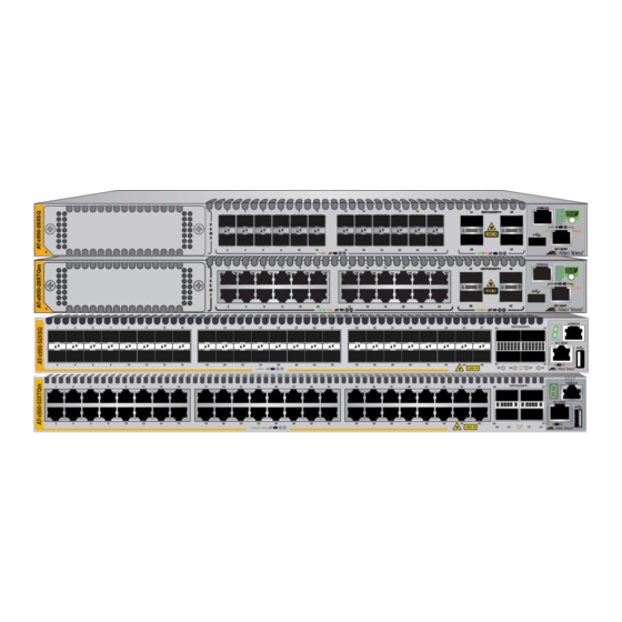
Chapter 1: Overview x950 Switches Table 1 lists the hardware components for the x950 Switches. Table 1. x950 Switch Components 1M/1G/2.5G/ QSFP+/QSFP28 Ports SFP/ 5G/10G for 40G/100G XEM2 eco-friendly Model SFP+ Copper Transceivers and 10G Line Card Button Ports Ports Breakout Cables AT-x950-28XSQ 1 to 24... -
Page 21: Figure 2: Front Panels Of The At-X950-52Xsq And At-X950-52Xtqm Switches
x950 Series Installation Guide for Standalone Switches Figure 2 shows the front panels of the AT-x950-52XSQ and AT-x950-52XTQm Switches. Management Panel AT-x950-52XSQ Switch SFP/SFP+ Ports 1 to 48: QSFP+/QSFP28 Ports 1/2.5/5/10G Transceivers 49, 53, 57, 61: 40G/100G Transceivers and 10G Breakout Cables Management Panel AT-x950-52XTQm Switch QSFP+/QSFP28 Ports... -
Page 22: Features
Chapter 1: Overview Features The main hardware features of the x950 Switches are listed here. Hardware The switch has the following hardware features: Features 1RU height 24 ports on the AT-x950-28XSQ Switch for 1G/2.5G/5G/10G SFP/ SFP+ transceivers. Refer to “1G SFP and 10G SFP+ Ports on the AT-x950-28XSQ and AT-x950-52XSQ Switches”... -
Page 23: Xem2 Ethernet Line Cards
Refer to “AT-XEM2-1CQ Line Card” on page 78. Line cards are ordered separately. Refer to the product data sheet on the Allied Telesis web site for a list of approved transceivers. Management Here are the management software and interfaces: Software and AlliedWare Plus management software. -
Page 24: Management Panel
Chapter 1: Overview Management The management panel has the following features: Panel Console RS-232 port for local management (no IP address required). USB 2.0 port for storing backup copies of system configuration files, updating management software, and other management functions. -
Page 25: Sfp And 10G Sfp+ Ports On The At-X950-28Xsq And At-X950-52Xsq Switches
They support full-duplex mode only. You can set the port speeds with Auto-Negotiation or manually. The default is Auto-Negotiation. Transceivers must be purchased separately. For a list of supported transceivers, refer to the product data sheet on the Allied Telesis web site. -
Page 26: Leds
Chapter 1: Overview LEDs The LEDs are located between the ports. Each port has one LED. Refer to Figure 4. Top Port LED Bottom Port LED Figure 4. Link and Activity LEDs for 1G SFP and 10G SFP+ Ports The LEDs display link and activity status. The possible LED states are described in Table 2. -
Page 27: Copper Ports On The At-X950-28Xtqm And At-X950-52Xtqm Switches
x950 Series Installation Guide for Standalone Switches Copper Ports on the AT-x950-28XTQm and AT-x950-52XTQm Switches The specifications for copper ports 1 to 24 on the AT-x950-28XTQm Switch and ports 1 to 48 on the AT-x950-52XTQm Switch are listed in Table 3. Table 3. -
Page 28: Leds
Chapter 1: Overview LEDs This section explains the LEDs for the 100M/1G/2.5G/5G/10G copper ports on the AT-x950-28XTQm and AT-x950-52XTQm Switches. Each port has one LED that displays link and activity information. The LEDs are shown in Figure 5. Bottom Port LED Top Port LED Figure 5. - Page 29 x950 Series Installation Guide for Standalone Switches Table 4. Link and Activity LEDs for Copper Ports on AT-x950-28XTQm and AT-x950-52XTQm Switches (Continued) State Description Possible causes of this state are listed here: - The port has not established a link with another network device.
-
Page 30: Ports For 40G Qsfp+ And 100G Qsfp28 Transceivers, And Breakout Cables
Chapter 1: Overview Ports for 40G QSFP+ and 100G QSFP28 Transceivers, and Breakout Cables The x950 Switches have four ports that support the transceivers and cables listed in Table 5. Table 5. Ports for QSFP+ and QSFP28 Transceivers, and 4x10G Beakout Cables 100G 40G QSFP+ 4x10G Breakout... -
Page 31: Leds
x950 Series Installation Guide for Standalone Switches Figure 6. AT-QSFP-4SFP10G-3CU and AT-QSFP-4SFP10G-5CU Copper Breakout Cables LEDs The ports for the QSFP28 and QSFP+ transceivers and breakout cables have one link and activity status LED. Refer to Figure 7. Top Transceiver or Bottom Transceiver or Breakout Cable LED Breakout Cable LED... -
Page 32: Table 6: Link And Activity Status Leds For 40G Qsfp+ And 100G Qsfp28 Transceivers
Chapter 1: Overview LEDs for 40G QSFP+ and 100G QSFP28 Transceivers The states of the LEDs for 40G QSFP+ and 100G QSFP28 transceivers are defined in Table 6. Table 6. Link and Activity Status LEDs for 40G QSFP+ and 100G QSFP28 Transceivers State Description... -
Page 33: Port Numbering For The At-X950-28Xsq And At-X950-28Xtqm Switches
x950 Series Installation Guide for Standalone Switches Table 7. Link and Activity Status LEDs for 10G Breakout Cables State Description Flashing Amber At least one of the four ports on the breakout cable is sending or receiving data. Possible causes of this state are listed here: - The transceiver slot is empty. -
Page 34: Port Numbering For The At-X950-52Xsq And At-X950-52Xtqm Switches
Chapter 1: Overview Table 8. Port Numbering for Ports 25 to 37 (Continued) With Fiber Optic With Breakout Port Transceiver or Cable Direct Attach Cable port1.0.37 port1.0.37 port1.0.38 port1.0.39 port1.0.40 Port Numbering Table 9 lists the port numbering system for ports 49, 53, 57, and 61 on the AT-x950-52XSQ and AT-x950-52XTQm Switches when the switch is for the operating as a standalone unit, with the VCStack feature disabled:... -
Page 35: Management Panel
x950 Series Installation Guide for Standalone Switches Management Panel The components on the management panel on the AT-x950-28XSQ and AT-x950-28XTQm Switches are identified in Figure 9. CONSOLE Switch ID LED RS-232 Serial Port eco-friendly Button USB Slot NET MGMT Port Figure 9. -
Page 36: Usb Port
Chapter 1: Overview USB Port The USB port in the management panel may be used to perform a variety of management functions. Examples of features that support the USB port are listed in Table 10. Table 10. Examples of Switch Features that Support the USB Port AlliedWare Plus Feature Command... - Page 37 x950 Series Installation Guide for Standalone Switches Table 10. Examples of Switch Features that Support the USB Port AlliedWare Plus Feature Command Close all open files and stop all UNMOUNT management actions on a USB storage device. You should always perform this command before removing a storage device from the drive, to prevent corrupting data files.
- Page 38 Chapter 1: Overview Table 10. Examples of Switch Features that Support the USB Port AlliedWare Plus Feature Command Allied Telesis Management Framework (AMF) Remove guest node’s backup files. ATMF BACKUP GUESTS DELETE Initiate manual synchronization of all guest ATMF BACKUP GUESTS...
-
Page 39: Net Mgmt Ethernet Management Port
x950 Series Installation Guide for Standalone Switches Table 10. Examples of Switch Features that Support the USB Port AlliedWare Plus Feature Command Retrieves and stores technical support WIRELESS GET-TECH files from managed wireless access points SC-PROFILE that use the specified Smart Connect (SC) Profile ID. -
Page 40: Console (Rs-232) Port
Chapter 1: Overview The Network Management (NET MGMT) port has one Status LED, described in Table 11. Table 11. NET MGMT Port LED State Description Solid Green The port has established a 1000M link with a network device. Flashing Green The port is transmitting or receiving data at 1000M. -
Page 41: Figure 11: Switch Id Led With The Eco-Friendly Mode Disabled
x950 Series Installation Guide for Standalone Switches The switch is booting up. The switch has encountered a fault condition. The VCStack feature is disabled. The switch is operating as a stand-alone unit, with the ID number 1. The switch is a member of a VCStack and has an ID number in the range of 1 to 8. -
Page 42: Eco-Friendly Button
Chapter 1: Overview eco-friendly You use the eco-friendly button on the management panel to turn the LEDs on or off. You might turn off the LEDs when you are not using them Button to monitor the switch, to conserve electricity. When the LEDs are off, the overall power consumption of the chassis is reduced by approximately 2 watts. -
Page 43: Direct Attach Cables
x950 Series Installation Guide for Standalone Switches Direct Attach Cables The optional direct attach cables listed in Table 12 offer an economical way to add 10G, 40G, and 100G connections over short distances for switch base ports and ports on XEM2 Line Cards. Table 12. -
Page 44: At-Pwr600 And At-Pwr600R Ac And Dc Power Supplies
Chapter 1: Overview AT-PWR600 and AT-PWR600R AC and DC Power Supplies The x950 Switches have four power supplies: AT-PWR600 AT-PWR600R AT-PWR600-80 AT-PWR600R-80 The power supplies differ in terms of AC or DC input power and airflow direction. -
Page 45: Figure 13: At-Pwr600 Power Supply And At-Fan05 Fan Module
x950 Series Installation Guide for Standalone Switches The AT-PWR600 AC Power Supply is shown in Figure 13. Airflow Direction Model Name Airflow - Front-to-Rear Figure 13. AT-PWR600 Power Supply and AT-FAN05 Fan Module... -
Page 46: Figure 14: At-Pwr600R Ac Power Supply And At-Fan05R Fan Module
Chapter 1: Overview The AT-PWR600R AC Power Supply is shown in Figure 14. Airflow Direction Model Name Airflow - Rear-to-Front Figure 14. AT-PWR600R AC Power Supply and AT-FAN05R Fan Module... -
Page 47: Figure 15: At-Pwr600-80 Dc Power Supply And At-Fan05 Fan Module
x950 Series Installation Guide for Standalone Switches The AT-PWR600-80 DC Power Supply is shown in Figure 15. Airflow Direction Model Name Airflow - Front-to-Rear Figure 15. AT-PWR600-80 DC Power Supply and AT-FAN05 Fan Module... -
Page 48: Figure 16: At-Pwr600R-80 Dc Power Supply And At-Fan05R Fan Module
Chapter 1: Overview The AT-PWR600R-80 DC Power Supply is shown in Figure 16. Airflow Direction Model Name Airflow - Rear-to-Front Figure 16. AT-PWR600R-80 DC Power Supply and AT-FAN05R Fan Module... -
Page 49: Power Supply Guidelines
the rear panel of the chassis. If you are installing only one power supply, Allied Telesis recommends installing it in PSU A slot because that slot does not come with a blank slot cover. If you are installing two power supplies, they can be both AC, both ... -
Page 50: Table 15: Leds On The At-Pwr600-80 And At-Pwr600R-80 Dc Power Supplies
Chapter 1: Overview Table 14. LEDs on the AT-PWR600 and AT-PWR600R AC Power Supplies (Continued) Green LED Amber LED Description Solid green Blinking amber The power supply is experiencing a warning condition, but is still operating. Possible causes are listed here: - The power supply is overheating. - Page 51 x950 Series Installation Guide for Standalone Switches Table 15. LEDs on the AT-PWR600-80 and AT-PWR600R-80 DC Power Supplies (Continued) Green LED Amber LED Description Solid green Blinking amber The power supply is experiencing a warning condition, but is still operating. Possible causes are listed here: - The power supply is overheating.
-
Page 52: At-Fan05 And At-Fan05R Fan Modules
Chapter 1: Overview AT-FAN05 and AT-FAN05R Fan Modules The x950 Switches have two fan modules: AT-FAN05 AT-FAN05R Refer to Figure 17. Model Name Figure 17. AT-FAN05 and AT-FAN05R Fan Modules The two fan modules have different airflow directions: AT-FAN05 module: Front-to-rear of switch. - Page 53 x950 Series Installation Guide for Standalone Switches For information on the power supplies, refer to “AT-PWR600 and AT-PWR600R AC and DC Power Supplies” on page 44. Here are the guidelines to the fan modules: Note The x950 Switches come with two pre-installed AT-FAN05 modules in FAN A and FAN B slots on the rear panel.
-
Page 54: Designating Ports In The Command Line Interface
Identifies the switch’s ID number. Please review the following: - The default value is 1. - Allied Telesis recommends using the default value for standalone switches. - A standalone switch that was previously a stack member retains its ID number from the stack. -
Page 55: Base Ports And Xem2 Line Card Ports
x950 Series Installation Guide for Standalone Switches Table 17. PORT Parameter Format for a Standalone Switch (Continued) Number Description Slot Number Identifies whether ports are base ports or ports on an XEM2 Line Card. The slot values are: - 0 - Identifies base ports. - 1- Indicates ports on the XEM2 Line Card in AT-x950-28XSQ and AT-x950-28XTQm Switches. -
Page 56: Examples For The Port Parameter On Base Ports
Chapter 1: Overview Examples for the Here are examples of the PORT parameter in the INTERFACE command for base ports on standalone switches. You must include the PORT PORT Parameter parameter with port numbers when specifying individual ports. The first on Base Ports example enters the port interface modes for base ports 11 and 14: awplus>... -
Page 57: Table 18: Port Numbers With And Without Breakout Cables On The At-X950-28Xtqm And At-X950-28Xsq Switches
x950 Series Installation Guide for Standalone Switches Table 18. Port Numbers with and without Breakout Cables on the AT-x950-28XTQm and AT-x950-28XSQ Switches Port Numbers without Breakout Port Numbers with Breakout Cables Cables 25-28 29-32 33-36 37-40 The port numbers with and without breakout cables for the 40G/100G QSFP+/QSFP28 ports on the AT-x950-52XTQm and AT-x950-52XSQ Switches are listed in Table 19. - Page 58 Chapter 1: Overview To identify a 40G/100G port without a breakout cable in the command line interface, use the first port of the range. For example, to enter the port interface mode in the command line interface for port 33 in the AT-x950-28XSQ or AT-x950-28XTQm Switch, you enter these commands: awplus>...
-
Page 59: Software And Hardware Releases
x950 Series Installation Guide for Standalone Switches Software and Hardware Releases The software and hardware releases for the AlliedWare Plus operating software and x950 Switches are listed in Table 21. Table 21. Software and Hardware Releases Software Version Hardware / VCStack v5.4.8-2 AT-x950-28XSQ Switch AT-XEM2-12XT Line Card... - Page 60 Chapter 1: Overview...
-
Page 61: Chapter 2: Xem2 Ethernet Line Cards
Chapter 2 XEM2 Ethernet Line Cards The chapter contains the following sections: “Overview” on page 62 “AT-XEM2-8XSTm Line Card” on page 65 “AT-XEM2-12XT Line Card” on page 69 “AT-XEM2-12XTm Line Card” on page 71 “AT-XEM2-12XS and AT-XEM2-12XS v2 Line Cards” on page 73 ... -
Page 62: Overview
Chapter 2: XEM2 Ethernet Line Cards Overview The AT-x950-28XSQ and AT-x950-28XTQm Switches have one expansion slot on the front panel for an optional XEM2 Line Card. See Figure 21. Note The AT-x950-52XSQ-52XSQ and AT-x950-52XTQm Switches do not support XEM2 Line Cards. AT-XEM2-8XSTm AT-XEM2-12XT AT-XEM2-12XTm... -
Page 63: Table 22: Xem2 Ethernet Line Cards
x950 Series Installation Guide for Standalone Switches The XEM2 Ethernet Line Cards are described in Table 22. Table 22. XEM2 Ethernet Line Cards Line Card Description AT-XEM2-8XSTm Four copper ports (1-4) with RJ-45 connectors that support the following speeds: - 100M - 1G/2.5G/5G/10G Four ports (5-8) that support the following types of transceivers:... - Page 64 Chapter 2: XEM2 Ethernet Line Cards Table 22. XEM2 Ethernet Line Cards (Continued) Line Card Description AT-XEM2-12XS and 12 ports that support the following types of AT-XEM2-12XS v2 transceivers: - 1G SFP - 10G SFP+ - 10G one meter AT-SP10TW1, three meter AT-SP10TW3, and seven meter AT-SP10TW7 direct connect twinax cables (The AT-XEM2-12XS v2 Card...
-
Page 65: At-Xem2-8Xstm Line Card
x950 Series Installation Guide for Standalone Switches AT-XEM2-8XSTm Line Card The AT-XEM2-8XSTm Line Card is shown in Figure 22. Figure 22. AT-XEM2-8XSTm Line Card Copper Ports The AT-XEM2-8XSTm Card has four copper ports and four SFP ports. The specifications for the copper ports are listed in Table 23. Table 23. -
Page 66: Copper Port Leds
Chapter 2: XEM2 Ethernet Line Cards Table 23. Copper Ports on the AT-XEM2-8XSTm Line Card (Continued) Specification Description Cabling Minimum cable requirements are: - 100M - Standard TIA/EIA 568-B-compliant Category 3 unshielded cabling. - 1G/2.5G/5G - Standard TIA/EIA 568-A-compliant Category 5 or TIA/EIA 568-B-compliant Enhanced Category 5 (Cat 5e) unshielded cabling. -
Page 67: Transceiver Ports
You can set the port speeds with Auto-Negotiation or manually. The default is Auto-Negotiation. SFP and SFP+ transceivers are purchased separately. For a list of supported transceivers, refer to the SBx908 GEN2 Series data sheet on the Allied Telesis web site. -
Page 68: Transceiver Port Leds
Chapter 2: XEM2 Ethernet Line Cards Transceiver Port The ports have link and activity LEDs. The states of the LEDs are described in Table 25. LEDs Table 25. Link and Activity LEDs for the SFP Ports on the AT-XEM2-8XSTm Line Card State Description Solid Green... -
Page 69: At-Xem2-12Xt Line Card
x950 Series Installation Guide for Standalone Switches AT-XEM2-12XT Line Card The AT-XEM2-12XT Line Card is shown in Figure 23. Figure 23. AT-XEM2-12XT Line Card Copper Ports The card has 12 copper ports with standard 8-pin RJ-45 ports. The specifications of the ports are listed in Table 26. Table 26. -
Page 70: Leds
Chapter 2: XEM2 Ethernet Line Cards Table 26. Copper Ports on the AT-XEM2-12XT Line Card (Continued) Specification Description Cabling The minimum cable requirements are: - 100M - Standard TIA/EIA 568-B-compliant Category 3 unshielded cabling. - 1G - Standard TIA/EIA 568-A-compliant Category 5 or TIA/EIA 568-B-compliant Enhanced Category 5 (Cat 5e) unshielded cabling. -
Page 71: At-Xem2-12Xtm Line Card
x950 Series Installation Guide for Standalone Switches AT-XEM2-12XTm Line Card The AT-XEM2-12XTm Card is shown in Figure 24. Figure 24. AT-XEM2-12XTm Line Card Copper Ports The AT-XEM2-12XTm Card has 12 copper ports with standard 8-pin RJ-45 ports. The specifications of the ports are listed in Table 28. Table 28. -
Page 72: Leds
Chapter 2: XEM2 Ethernet Line Cards Table 28. Copper Ports on the AT-XEM2-12XTm Line Card (Continued) Specification Description Cabling The minimum cable requirements are: - 100M - Standard TIA/EIA 568-B-compliant Category 3 unshielded cabling. - 1G/2.5G/5G - Standard TIA/EIA 568-A-compliant Category 5 or TIA/EIA 568-B-compliant Enhanced Category 5 (Cat 5e) unshielded cabling. -
Page 73: At-Xem2-12Xs And At-Xem2-12Xs V2 Line Cards
x950 Series Installation Guide for Standalone Switches AT-XEM2-12XS and AT-XEM2-12XS v2 Line Cards The AT-XEM2-12XS Line Card is shown in Figure 25. Figure 25. AT-XEM2-12XS Line Card Transceiver Ports The card has twelve ports that support the following types of 1G SFP, 10G SFP+, and 1G/2.5G/5G/10G transceivers with RJ-45 connectors: 1G SX or LX SFP transceivers ... -
Page 74: Card Versions
Chapter 2: XEM2 Ethernet Line Cards You can set the port speeds with Auto-Negotiation or manually. The default is Auto-Negotiation. SFP or SFP+ transceivers must be purchased separately. For a list of supported transceivers, refer to the x950 Switches data sheet on the Allied Telesis web site. - Page 75 x950 Series Installation Guide for Standalone Switches Table 30. Port Link and Activity LEDs on the AT-XEM2-12XS Line Card State Description Possible causes of this state are listed here: - The transceiver has not established a link with another network device. - The LEDs are turned off.
-
Page 76: At-Xem2-4Qs Line Card
Chapter 2: XEM2 Ethernet Line Cards AT-XEM2-4QS Line Card The AT-XEM2-4QS Line Card is shown in Figure 27. Figure 27. AT-XEM2-4QS Line Card Transceiver Ports Here are examples of the types of 40G QSFP+ transceivers supported by the line card: AT-QSFPSR4 transceiver - Maximum operating distance of 150 ... -
Page 77: Leds
x950 Series Installation Guide for Standalone Switches LEDs The LED states for transceivers or direct attach cables in ports on the AT-XEM2-4QS Line Card are described in Table 31. Table 31. Port Link and Activity Status LEDs on the AT-XEM2-4QS Line Card State Description... -
Page 78: At-Xem2-1Cq Line Card
Chapter 2: XEM2 Ethernet Line Cards AT-XEM2-1CQ Line Card The AT-XEM2-1CQ Line Card is shown in Figure 28. Figure 28. AT-XEM2-1CQ Line Card Transceiver Port Here are examples of the types of 100G QSFP28 transceivers supported by the line card: AT-QSFP28-SR4 transceiver - Maximum operating distance of ... -
Page 79: Leds
x950 Series Installation Guide for Standalone Switches LEDs The LED states for the port in the AT-XEM2-1CQ Line Card are described in Table 33 on page 79. Table 33. Port Link and Activity Status LED on the AT-XEM2-1CQ Line Card State Description Solid Green... - Page 80 Chapter 2: XEM2 Ethernet Line Cards...
-
Page 81: Chapter 3: Beginning The Installation
Chapter 3 Beginning the Installation The chapter contains the following sections: “Reviewing Safety Precautions” on page 82 “Installation Options” on page 87 “Choosing a Site for the Chassis” on page 88 “Unpacking the Switch” on page 89 ... -
Page 82: Reviewing Safety Precautions
Chapter 3: Beginning the Installation Reviewing Safety Precautions Please review the following safety precautions before beginning the installation procedure. Note Safety statements that have the symbol are translated into multiple languages in the Translated Safety Statements document at www.alliedtelesis.com/support. Warning Class 1 Laser product. - Page 83 x950 Series Installation Guide for Standalone Switches Warning Power cord is used as a disconnection device. To de-energize equipment, disconnect the power cord. E3 Warning Class I Equipment. This equipment must be earthed. The power plug must be connected to a properly wired earth ground socket outlet.
- Page 84 Mounting of the equipment in the rack should be such that a hazardous condition is not created due to uneven mechanical loading. E25 Warning The chassis may be heavy and awkward to lift. Allied Telesis recommends that you get assistance when mounting the chassis in an equipment rack. E28...
- Page 85 x950 Series Installation Guide for Standalone Switches Note Use dedicated power circuits or power conditioners to supply reliable electrical power to the device. E27 Warning This unit might have more than one power cord. To reduce the risk of electric shock, disconnect all power cords before servicing the unit.
- Page 86 Chapter 3: Beginning the Installation Warning This equipment shall be installed in a Restricted Access location. E45 Caution The unit does not contain serviceable components. Please return damaged units for servicing. E42 Warning The temperature of an operational SFP or SFP+ transceiver may exceed 70°...
-
Page 87: Installation Options
x950 Series Installation Guide for Standalone Switches Installation Options Here are installation options for the x950 Switches: The AT-x950-28XSQ and AT-x950-28XTQm Switches support the XEM2 Line Cards. Refer to “Installing XEM2 Ethernet Line Cards” on page 106. The switch has four installation options. Refer to Figure 29. ... -
Page 88: Choosing A Site For The Chassis
Chapter 3: Beginning the Installation Choosing a Site for the Chassis Observe these site requirements. If you are installing the device in an equipment rack, check that the rack is safely secured so that it will not tip over. Devices should be installed in the rack starting at the bottom, with the heavier devices near the bottom of the rack. -
Page 89: Unpacking The Switch
x950 Series Installation Guide for Standalone Switches Unpacking the Switch To unpack the switch from its shipping box, perform the following procedure: 1. Remove the accessories and documents from the accessory box partition. Refer to Figure 30. Figure 30. Removing Accessories 2. -
Page 90: Figure 31: Removing The Shipping Box Partition
Chapter 3: Beginning the Installation Figure 31. Removing the Shipping Box Partition 3. Lift the switch from the shipping box and place it on a level, secure table. Refer to Figure 32 on page 91. Warning The device is heavy. Always ask for assistance before moving or lifting it to avoid injure yourself or damage the equipment. -
Page 91: Figure 32: Lifting The Switch From The Shipping Box
x950 Series Installation Guide for Standalone Switches Figure 32. Lifting the Switch from the Shipping Box 4. Remove the switch from the shipping end-caps and protective bag. Refer to Figure 33. Figure 33. Removing the Switch from the Shipping End-caps and Protective Bag... - Page 92 Chapter 3: Beginning the Installation 5. Visually inspect the product for damage. 6. Visually inspect the front panel for the components shown in Figure 1 on page 20 and Figure 2 on page 21. 7. Verify that there are two pre-installed FAN05 fan modules in FAN A and FAN B slots on the rear panel.
-
Page 93: Verifying The Accessory Kit
x950 Series Installation Guide for Standalone Switches Verifying the Accessory Kit Table 34 lists the accessory items included with the switch. Table 34. Accessory Kit Item Description One 2 m (6.6 ft) local management cable with RJ-45 (8P8C) and DB-9 (D-sub 9-pin) connectors. -
Page 94: Table 35: Additional Accessory Kit For The At-X950-52Xsq And At-X950-52Xtqm Switches
Eight M4x7mm screws for the rack mounting brackets Note If any item is missing or damaged, contact your Allied Telesis sales representative for assistance. After unpacking the switch and verifying the accessory kit, go to “Unpacking PWR600 AC and DC Power Supplies” on page 95. -
Page 95: Unpacking Pwr600 Ac And Dc Power Supplies
x950 Series Installation Guide for Standalone Switches Unpacking PWR600 AC and DC Power Supplies To unpack AT-PWR600, AT-PWR600R, AT-PWR600-80, and AT- PWR600R-80 Power Supplies, perform the following procedure: 1. Remove the power cord and any documents from the accessory box partition. -
Page 96: Figure 35: Removing The Partition From The Power Supply Shipping Box
Chapter 3: Beginning the Installation 2. Remove the partition from the shipping box. Refer to Figure 35. Figure 35. Removing the Partition from the Power Supply Shipping Box 3. Lift the power supply from the shipping box and place it on a level, secure table. -
Page 97: Figure 36: Removing The Power Supply From The Shipping Box
x950 Series Installation Guide for Standalone Switches Figure 36. Removing the Power Supply from the Shipping Box 4. Remove the power supply from the shipping end-caps and protective shipping bag. Refer to Figure 37. Figure 37. Removing the Power Supply from the Shipping End-caps and Protective Bag 5. - Page 98 Chapter 3: Beginning the Installation...
-
Page 99: Chapter 4: Installing Power Supplies And Xem2 Line Cards
Chapter 4 Installing Power Supplies and XEM2 Line Cards This chapter has the following procedures: “Installing AT-PWR600 and AT-PWR600R AC Power Supplies” on page 100 “Installing AT-PWR600-80 and AT-PWR600R-80 DC Power Supplies” on page 104 “Installing XEM2 Ethernet Line Cards” on page 106 ... -
Page 100: Installing At-Pwr600 And At-Pwr600R Ac Power Supplies
PSU A and PSU B on the left side of the rear panel. If you are installing only one power supply, you can install it in either slot. Allied Telesis recommends PSU A because that slot does not come with a blank power supply panel. -
Page 101: Figure 38: Removing The Blank Power Supply Panel From Slot Psu B
x950 Series Installation Guide for Standalone Switches Release Tab Figure 38. Removing the Blank Power Supply Panel from Slot PSU B... -
Page 102: Figure 39: Sliding The At-Pwr600 Or At-Pwr600R Ac Power Supply Into The Chassis
Chapter 4: Installing Power Supplies and XEM2 Line Cards 3. Carefully align the power supply in the slot and slide it into the slot. Figure 39 shows the module aligned for the PSU A slot. Figure 39. Sliding the AT-PWR600 or AT-PWR600R AC Power Supply into the Chassis 4. -
Page 103: Figure 40: Seating The Power Supply On The Internal Connector
x950 Series Installation Guide for Standalone Switches Figure 40. Seating the Power Supply on the Internal Connector 5. Visually inspect the power supply to be sure that its faceplate is flush against the rear panel of the chassis. 6. If you purchased two AC power supplies for the switch, repeat this procedure to install the second unit. -
Page 104: Installing At-Pwr600-80 And At-Pwr600R-80 Dc Power Supplies
PSU A and PSU B on the left side of the rear panel. If you are installing only one power supply, you can install it in either slot. Allied Telesis recommends PSU A because that slot does not come with a blank power supply panel. -
Page 105: Figure 41: Sliding The At-Pwr600 Dc Power Supply Into The Chassis
x950 Series Installation Guide for Standalone Switches Figure 41. Sliding the AT-PWR600 DC Power Supply into the Chassis 4. When the power supply makes contact with the connector inside the switch, gently press on its faceplate to seat it on the connector. 5. -
Page 106: Installing Xem2 Ethernet Line Cards
Chapter 4: Installing Power Supplies and XEM2 Line Cards Installing XEM2 Ethernet Line Cards This section contains the procedure for installing an XEM2 Line Card in the expansion slot in the front panel of the AT-x950-28XSQ and AT-x950- 28XTQm Switches. For background information, refer to Chapter 2, “XEM2 Ethernet Line Cards”... -
Page 107: Figure 43: Removing The Xem2 Line Card From The Anti-Static Bag
x950 Series Installation Guide for Standalone Switches 2. Carefully remove the line card from its shipping container and anti- static bag. Refer to Figure 43. Figure 43. Removing the XEM2 Line Card from the Anti-static Bag 3. Position the line card with the notch on the faceplate in the bottom left corner, as shown in Figure 44, and carefully slide it into the slot. -
Page 108: Figure 45: Seating The Xem2 Line Card In The Expansion Slot
Chapter 4: Installing Power Supplies and XEM2 Line Cards 4. When the line card makes contact with the internal connector in the switch, gently press on the sides of its faceplate to seat it on the connector. Refer to Figure 45. Figure 45. -
Page 109: Figure 46: Tightening The Two Captive Screws On The Xem2 Line Card
x950 Series Installation Guide for Standalone Switches Figure 46. Tightening the Two Captive Screws on the XEM2 Line Card 7. After installing the power supplies and XEM2 Line Card, go to one of the following chapters: Chapter 5, “Installing the Switch on a Table” on page 111 ... - Page 110 Chapter 4: Installing Power Supplies and XEM2 Line Cards...
-
Page 111: Chapter 5: Installing The Switch On A Table
Chapter 5 Installing the Switch on a Table This chapter contains the instructions for installing the switch on a table or desktop. Warning Switches should not be stacked on a table or desktop. They could present a physical safety hazard if you need to move or replace switches. -
Page 112: Figure 48: Holes For Bumper Feet
Chapter 5: Installing the Switch on a Table Rear of Chassis Front of Chassis Figure 48. Holes for Bumper Feet Note The following procedure assumes that you have already reviewed the information and performed the procedures in Chapter 3, “Beginning the Installation” on page 81. To install the switch on a table, perform the following procedure: 1. -
Page 113: Figure 50: Placing The Bumper Foot On A Base Corner Hole
x950 Series Installation Guide for Standalone Switches 3. Place the bumper foot onto one of the holes in the base of the switch. Refer to Figure 50. Figure 50. Placing the Bumper Foot on a Base Corner Hole 4. Insert the rivet to secure the bumper foot to the base. Refer to Figure 51. - Page 114 Chapter 5: Installing the Switch on a Table 7. Do one of the following: To install AC power supplies, go to “Installing AT-PWR600 and AT- PWR600R AC Power Supplies” on page 100. To install DC power supplies, go to “Installing AT-PWR600-80 and ...
-
Page 115: Chapter 6: Installing The Switch In An Equipment Rack
Chapter 6 Installing the Switch in an Equipment Rack This chapter contains instructions for installing the switch in a standard 19- inch equipment rack. The procedures are listed here: “Beginning the Installation” on page 116 “Removing the Bumper Feet” on page 118 ... -
Page 116: Beginning The Installation
Chapter 6: Installing the Switch in an Equipment Rack Beginning the Installation This chapter contains the procedure for installing the switch in a standard 19-inch equipment rack, with the brackets included with the unit. Required Items The following items are required to install the switch in an equipment rack: Two equipment rack brackets (included with the switch) ... -
Page 117: Figure 54: Switch Orientations In An Equipment Rack
x950 Series Installation Guide for Standalone Switches You can install the switch with its front panel flush with or extending in front of the equipment rack. The illustrations in Figure 54 show the possible switch orientations in the equipment rack. Figure 54. -
Page 118: Removing The Bumper Feet
Chapter 6: Installing the Switch in an Equipment Rack Removing the Bumper Feet The bumper feet included with the switch should not be used when installing the device in an equipment rack. If they are already installed, perform the following procedure to remove them: 1. -
Page 119: Installing The Switch
Please review the information and perform the procedures in Chapter 3, “Beginning the Installation” on page 81 before installing the switch. Caution The chassis may be heavy and awkward to lift. Allied Telesis recommends that you get assistance when mounting the chassis in an equipment rack. E28... -
Page 120: Figure 56: Attaching The Equipment Rack Brackets
Chapter 6: Installing the Switch in an Equipment Rack Figure 56. Attaching the Equipment Rack Brackets 4. Have another person hold the switch in the equipment rack while you secure it using standard equipment rack screws (not provided). Refer to Figure 57. Figure 57. - Page 121 x950 Series Installation Guide for Standalone Switches 5. Do one of the following: To install power supplies, go to “Installing AT-PWR600 and AT- PWR600R AC Power Supplies” on page 100. To install an XEM2 Ethernet Line Card, go to “Installing XEM2 ...
- Page 122 Chapter 6: Installing the Switch in an Equipment Rack...
-
Page 123: Chapter 7: Installing The Switch On A Wall
Chapter 7 Installing the Switch on a Wall The procedures in this chapter are listed here: “Switch Orientations on a Wall” on page 124 “Recommended Minimum Wall Area Dimensions” on page 125 “Plywood Base for a Wall with Wooden Studs” on page 127 ... -
Page 124: Switch Orientations On A Wall
Chapter 7: Installing the Switch on a Wall Switch Orientations on a Wall You can install the switch on a wall with the front panel on the left or right, as shown in Figure 58. Do not install it with the front panel on the top or bottom. -
Page 125: Recommended Minimum Wall Area Dimensions
x950 Series Installation Guide for Standalone Switches Recommended Minimum Wall Area Dimensions The recommended minimum dimensions for the reserved wall area for the switch are listed here: Width: 96 centimeters (36 inches) Height: 58 centimeters (23 inches) Figure 59 and Figure 60 on page 126 illustrate the recommended positions of the switch in the reserved area when the front panel is on the left and right, respectively. -
Page 126: Figure 60: Minimum Wall Area Dimensions With The Front Panel On The Right
Chapter 7: Installing the Switch on a Wall Figure 60. Minimum Wall Area Dimensions with the Front Panel on the Right... -
Page 127: Plywood Base For A Wall With Wooden Studs
x950 Series Installation Guide for Standalone Switches Plywood Base for a Wall with Wooden Studs If you are installing the switch on a wall that has wooden studs, Allied Telesis recommends using a plywood base for the device. (A plywood base is not required for a concrete wall.) Refer to Figure 61. -
Page 128: Figure 62: Steps To Installing The Switch With A Plywood Base
Chapter 7: Installing the Switch on a Wall The recommended minimum dimensions of the plywood base are listed here: Width: 58.4 centimeters (23 inches) Height: 55.9 centimeters (22 inches) Thickness: 5.1 centimeters (2 inches) The dimensions assume the wall studs are 41 centimeters (16 inches) apart. -
Page 129: Installation Guidelines
x950 Series Installation Guide for Standalone Switches Installation Guidelines Here are the guidelines to installing the switch on a wall: You may install the switch on a wall that has wooden studs. You may install it on a concrete wall. ... -
Page 130: Tools And Material
Chapter 7: Installing the Switch on a Wall Tools and Here are the required tools and material for installing the switch on a wall: Material Four standard brackets and 16 M3x6mm screws (included with the switch) listed in Table 34 on page 93. Four wood or concrete wall screws (included with the switch) ... -
Page 131: Installing The Plywood Base
x950 Series Installation Guide for Standalone Switches Installing the Plywood Base A plywood base is recommended when installing the switch on a wall that has wooden studs. Refer to “Plywood Base for a Wall with Wooden Studs” on page 127. Consult a qualified building contractor for installation instructions for the plywood base. -
Page 132: Installing The Switch On The Plywood Base
This procedure assumes that the plywood base for the switch is already installed on the wall. Please review “Reviewing Safety Precautions” on page 82 and “Choosing a Site for the Chassis” on page 88 before performing this procedure. Allied Telesis recommends a minimum of three people for this procedure. Warning The device is heavy. -
Page 133: Figure 64: Attaching The Switch To The Plywood Base
x950 Series Installation Guide for Standalone Switches The sides of the switch have two sets of holes. One set is for installing the switch on a wall with the brackets and the other is for the RKMT- SL01 Rack Mounting Kit. For this procedure, you need to use the bracket holes, identified in Figure 52 on page 116. - Page 134 Chapter 7: Installing the Switch on a Wall 4. Do one of the following: To install the power supplies or Ethernet line card, go to “Installing AT-PWR600 and AT-PWR600R AC Power Supplies” on page 100 and “Installing XEM2 Ethernet Line Cards” on page 106. If all the components are installed, go to Chapter 9, “Verifying and ...
-
Page 135: Installing The Switch On A Concrete Wall
Series Installation Guide for Standalone Switches Installing the Switch on a Concrete Wall Allied Telesis recommends a minimum of three people for this procedure. To install the switch on a concrete wall, perform the following procedure: Warning The device is heavy. Always ask for assistance before moving or lifting it to avoid injuring yourself or damaging the equipment. -
Page 136: Figure 65: Marking The Locations Of The Bracket Holes On A Concrete Wall
Prior to drilling, set the drill to hammer and rotation mode. The modes break up the concrete and clean out the hole. Allied Telesis recommends cleaning out the holes with a brush or compressed air. 6. Insert the four anchors into the holes. -
Page 137: Figure 66: Installing The Switch On A Concrete Wall
x950 Series Installation Guide for Standalone Switches Figure 66. Installing the Switch on a Concrete Wall 8. Do one of the following: To install the power supplies or XEM2 Line Card, go to “Installing AT-PWR600 and AT-PWR600R AC Power Supplies” on page 100 and “Installing XEM2 Ethernet Line Cards”... - Page 138 Chapter 7: Installing the Switch on a Wall...
-
Page 139: Chapter 8: Installing The Switch In The At-Rkmt-Sl01 Sliding Rack
Chapter 8 Installing the Switch in the AT-RKMT- SL01 Sliding Rack This chapter contains the following sections: “Introduction” on page 140 “Rack Mount Kit Components” on page 141 “Equipment Rack Requirements” on page 143 “Reviewing Safety Precautions” on page 144 ... -
Page 140: Introduction
Introduction The AT-RKMT-SL01 Rack Mount Kit is a slide-rail type rack-mount kit for Allied Telesis switches in EIA standard 19-inch equipment racks. The kit makes installation and maintenance of network equipment easier by letting you slide switches into or out of equipment racks, including server racks with deep dimensions. -
Page 141: Rack Mount Kit Components
x950 Series Installation Guide for Standalone Switches Rack Mount Kit Components The kit has three main components. Adjustable Outer Two adjustable outer rails attach to the equipment rack. They are suitable for racks with depths of 600 mm (23.6 in) to 900 mm (35.4 in). Refer to Rails Figure 67. -
Page 142: Figure 69: Extension Brackets
Chapter 8: Installing the Switch in the AT-RKMT-SL01 Sliding Rack Figure 69. Extension Brackets... -
Page 143: Equipment Rack Requirements
x950 Series Installation Guide for Standalone Switches Equipment Rack Requirements The Rack Mount Kit is designed for equipment racks that meet the following requirements: The depth can be from 600 mm (23.6 in) to 900 mm (35.4 in). The width should be a minimum of 452 mm (17.8 in). ... -
Page 144: Reviewing Safety Precautions
available in a PDF document titled Translated Safety Statements posted on the Allied Telesis website at www.alliedtelesis.com/ support. Warning Mounting of the equipment in the rack should be such that a hazardous condition is not created due to uneven mechanical loading. - Page 145 x950 Series Installation Guide for Standalone Switches Caution Use the adjustment bracket screws supplied with the inner rail. Using screws other than those supplied may result in equipment damage. Warning When installing the outer and inner rails, and adjustment bracket, ensure the components are securely attached with the appropriate screws.
-
Page 146: Installation Overview
Chapter 8: Installing the Switch in the AT-RKMT-SL01 Sliding Rack Installation Overview The following steps summarize the installation procedure for the AT- RKMT-SL01 Rack Mount Kit: 1. Verify the contents of the shipping box. Refer to “Unpacking the Shipping Container” on page 147. 2. -
Page 147: Unpacking The Shipping Container
x950 Series Installation Guide for Standalone Switches Unpacking the Shipping Container The contents of the shipping container are shown in Figure 70. Two inner rails - They attach to Two outer rails - They attach to the the sides of the switch. equipment rack. - Page 148 Chapter 8: Installing the Switch in the AT-RKMT-SL01 Sliding Rack Note Store the packaging material in a safe location. You should use the original shipping material if you need to return the kit to Allied Telesis. Warning When installing the outer and inner rails, and extension brackets, ensure the components are securely attached with the appropriate screws.
-
Page 149: Installing The Outer Rails On The Equipment Rack
x950 Series Installation Guide for Standalone Switches Installing the Outer Rails on the Equipment Rack To install the outer rails to the equipment rack, perform the following procedure. 1. Locate the FRONT and REAR labels on the sides of the rails. You have to install the rails with the FRONT labels at the front of the equipment rack and the REAR Labels at the back. -
Page 150: Figure 72: Installing The Outer Rails On The Equipment Rack
Chapter 8: Installing the Switch in the AT-RKMT-SL01 Sliding Rack Front of Equipment Rack Figure 72. Installing the Outer Rails on the Equipment Rack... -
Page 151: Installing The Extension Brackets On The Inner Rails
x950 Series Installation Guide for Standalone Switches Installing the Extension Brackets on the Inner Rails The kit comes with two extension brackets. Refer to Figure 73. Figure 73. Extension Brackets You use the brackets to recess the switch in the equipment rack. The maximum distance will depend on the depth of the rack. -
Page 152: Figure 75: Inserting An Inner Rail Into An Outer Rail
Chapter 8: Installing the Switch in the AT-RKMT-SL01 Sliding Rack Figure 75. Inserting an Inner Rail into an Outer Rail 2. Position the inner rail at the planned location for the front panel of switch in the sliding rack. Refer to Figure 76. Location of Front Panel of Switch Figure 76. -
Page 153: Assembling The Extension Brackets
x950 Series Installation Guide for Standalone Switches 4. Remove the inner rail from the outer rail. Refer to Figure 78. Figure 78. Removing the Inner Rail 5. Go to “Assembling the Extension Brackets,” next. Assembling the Now that you know the approximate length for the extension brackets, you are ready to assemble them. -
Page 154: Figure 80: Extension Bracket Configurations
Chapter 8: Installing the Switch in the AT-RKMT-SL01 Sliding Rack You adjust the lengths of the brackets by connecting them in different combinations. There are seven possible configurations. Refer to Figure 80. The default configuration is number 5. To adjust the extension brackets, perform the following procedure: 1. -
Page 155: Figure 81: Example Of Attaching The Extension Brackets To The Inner Rails
x950 Series Installation Guide for Standalone Switches Note The long brackets have to be used between the fixed and short brackets. You cannot connect them directly to the inner rails. 2. Assemble the extension brackets to match the selected length in the table. -
Page 156: Figure 82: Testing The Inner Rails With The Extension Brackets
Chapter 8: Installing the Switch in the AT-RKMT-SL01 Sliding Rack 4. To test the lengths of the extension brackets, slide the inner rails into the outer rails in the equipment rack. Refer to Figure 82. Figure 82. Testing the Inner Rails with the Extension Brackets 5. -
Page 157: Installing The Inner Rails On The Switch
x950 Series Installation Guide for Standalone Switches Installing the Inner Rails on the Switch The sides of the x950 Switches have two sets of bracket screw holes. The smaller M3 holes are for the standard brackets that come with the switch and the larger M4 screw holes are for the inner rails of the AT-RKMT-SL01 sliding rack. -
Page 158: Figure 86: Attaching The Inner Rails To The X950 Switch
Chapter 8: Installing the Switch in the AT-RKMT-SL01 Sliding Rack Figure 86. Attaching the Inner Rails to the x950 Switch Go to “Installing the Switch in the Equipment Rack” on page 159. -
Page 159: Installing The Switch In The Equipment Rack
x950 Series Installation Guide for Standalone Switches Installing the Switch in the Equipment Rack After attaching the inner rails and extension brackets to the switch, perform the following procedure to install the switch in the sliding rack: Warning When installing or removing the switch from the rack, disconnect the media and power cables. -
Page 160: Figure 88: Affixing The Warning Labels
Chapter 8: Installing the Switch in the AT-RKMT-SL01 Sliding Rack Figure 88. Affixing the Warning Labels 3. Slide the switch fully into the rack. 4. Tighten the two screws on the fixed brackets to secure the switch to the equipment rack. Refer to Figure 89. Figure 89. -
Page 161: Figure 90: Tightening The Screws On The Outer Rails
x950 Series Installation Guide for Standalone Switches Warning Pull the switch out slowly if you must remove it from the rack for maintenance. If you pull the switch out past the front of the rack posts, or if you pull it out too quickly, there is a risk that the weight of the switch will cause the sliding rail assemblies to fail and cause the switch to fall out. - Page 162 Chapter 8: Installing the Switch in the AT-RKMT-SL01 Sliding Rack...
-
Page 163: Chapter 9: Verifying And Configuring The Switch
Chapter 9 Verifying and Configuring the Switch This chapter contains the following procedures: “Powering on AT-PWR600 and AT-PWR600R AC Power Supplies” on page 164 “Wiring and Powering on AT-PWR600-80 and AT-PWR600R-80 DC Power Supplies” on page 167 “Starting a Local Management Session” on page 175 ... -
Page 164: Powering On At-Pwr600 And At-Pwr600R Ac Power Supplies
Chapter 9: Verifying and Configuring the Switch Powering on AT-PWR600 and AT-PWR600R AC Power Supplies This section contains the procedure for powering on a switch that has AT- PWR600 or AT-PWR600R Power Supplies. For instructions on installing the power supplies, refer to “Installing AT-PWR600 and AT-PWR600R AC Power Supplies”... -
Page 165: Figure 91: Connecting The Ac Power Cord
x950 Series Installation Guide for Standalone Switches Figure 91. Connecting the AC Power Cord 2. Move the power cord into the restraining strap and secure the strap by feeding it into the tab slot. Refer to Figure 92. Tab Slot Figure 92. -
Page 166: Figure 93: Connecting The Power Cord To An Ac Power Source
Chapter 9: Verifying and Configuring the Switch 3. Connect the power cord to an appropriate AC power source. The AC input voltage characteristic for the AC power supplies is 100 to 240V. Refer to Figure 93. Figure 93. Connecting the Power Cord to an AC Power Source Note The illustration shows the North American power cord. -
Page 167: Wiring And Powering On At-Pwr600-80 And At-Pwr600R-80 Dc Power Supplies
x950 Series Installation Guide for Standalone Switches Wiring and Powering on AT-PWR600-80 and AT-PWR600R-80 DC Power Supplies This section contains the procedure for powering on a switch that has AT- PWR600-80 or AT-PWR600R-80 DC Power Supplies. For instructions on installing the power supplies, refer to “Installing AT-PWR600-80 and AT- PWR600R-80 DC Power Supplies”... -
Page 168: Figure 94: Stripping The Grounding Wire
Chapter 9: Verifying and Configuring the Switch To connect the grounding wire with bare wire, perform the following procedure: 1. Strip 2.54cm (1.0 in.) of insulation from the end of the solid grounding wire with a wire insulator stripper. Refer to Figure 94. 2.54cm (1.0 in.) Figure 94. -
Page 169: Figure 96: Accessing The Connectors
x950 Series Installation Guide for Standalone Switches Figure 96. Accessing the Connectors 4. Loosen the ground screw with a Phillips-head screwdriver. Refer to Figure 97. Figure 97. Loosening the Ground Screw... -
Page 170: Connecting The Dc Power Wires
Chapter 9: Verifying and Configuring the Switch 5. Wind the grounding wire clockwise around the base of the grounding screw. Refer to Figure 98. Figure 98. Wrapping the Grounding Wire and Tightening the Screw 6. Tighten the ground screw. 7. Connect the other end of the ground wire to a ground point at the installation site. -
Page 171: Figure 100: Wrapping The Wire Strands
This step is to prevent loose strands from touching other wires and causing an electrical short. Note Allied Telesis recommends tinning the wires with solder for added protection against loose strands. This guide does not provide instructions on how to tin wires. -
Page 172: Figure 102. Tightening The Screw For The Negative
Chapter 9: Verifying and Configuring the Switch 4. Wind the power wire and tighten the screw. Refer to Figure 102. Figure 102. Tightening the Screw for the Negative (-) 5. Loosen the top screw for the positive (+) with a Phillips-head screwdriver. -
Page 173: Figure 104: Tightening The Screw For The Negative (+)
x950 Series Installation Guide for Standalone Switches 6. Wind the power wire and tighten the screw.Refer to Figure 104. Figure 104. Tightening the Screw for the Negative (+) 7. After attaching the wires to the screws, verify that there are no exposed wires or loose wire strands. -
Page 174: Powering On The Dc Power Supplies
Chapter 9: Verifying and Configuring the Switch 9. Tighten the screw for the cover panel. Refer to Figure 106. Figure 106. Tightening the Screw for the Cover Panel 10. If the switch has two DC power supplies, repeat the procedures staring with “Connecting the Grounding Wire”... -
Page 175: Starting A Local Management Session
x950 Series Installation Guide for Standalone Switches Starting a Local Management Session After powering on the switch and waiting several minutes for it to initialize the AlliedWare Plus management software, start a local management session using the Console port on the management panel, as explained in this section. -
Page 176: Figure 108: User Exec Mode Prompt
Chapter 9: Verifying and Configuring the Switch 3. Configure the VT-100 terminal or terminal emulation program as follows: Baud rate: 9600 bps Data bits: 8 Parity: None Stop bits: 1 Flow controller: None Note The port settings are for a DEC VT100 or ANSI terminal, or an equivalent terminal emulator program. -
Page 177: Verifying The Switch With Alliedware Plus Commands
52. Replace the power supplies and/or fan modules so that their airflow directions are the same. For information about the command line interface, refer to the Software Reference for AT-x950 Switches on the Allied Telesis web site. 5. Go to “Disabling VCStack” on page 178. -
Page 178: Disabling Vcstack
Chapter 9: Verifying and Configuring the Switch Disabling VCStack The procedure in this section explains how to disable the VCStack feature to use the unit as a standalone switch. You might not have to perform this procedure because the default setting for VCStack is disabled. A simple way to determine whether the VCStack feature is enabled or disabled is by viewing the Switch ID LED: If the LED is displaying “0”, the VCStack feature is already... -
Page 179: Figure 110: Moving To The Global Configuration Mode
x950 Series Installation Guide for Standalone Switches 5. Review the following items: If the Operational Status is “Stacking Hardware Disabled,” the VCStack feature is already disabled on the switch. Go to “Configuring Ports for 40G QSFP+ and 100G QSFP28 Transceivers, and Breakout Cables”... -
Page 180: Figure 113: Saving The Changes With The Write Command
Chapter 9: Verifying and Configuring the Switch 10. Enter the WRITE command to save your change in the configuration file. The switch displays the confirmation prompt in Figure 113. awplus# write Building configuration ... [OK] awplus# Figure 113. Saving the Changes with the WRITE Command If this is the first management session, the switch automatically creates the Default.cfg file in flash memory to store your changes. -
Page 181: Configuring Ports For 40G Qsfp+ And 100G Qsfp28 Transceivers, And Breakout Cables
x950 Series Installation Guide for Standalone Switches Configuring Ports for 40G QSFP+ and 100G QSFP28 Transceivers, and Breakout Cables The procedure in this section applies to the following ports: Ports 25, 29, 33, and 37 on AT-x950-28XSQ and AT-x950- 28XTQm Switches Ports 49, 53, 57, and 61 on AT-x950-52XSQ and AT-x950- ... - Page 182 Chapter 9: Verifying and Configuring the Switch The variables are defined here: The PORTS variable specifies the ports to be configured. Refer to “Designating Ports in the Command Line Interface” on page 54 for information. The 10gx4 parameter configures ports for breakout cables. ...
-
Page 183: Saving Your Changes And Rebooting The Switch
x950 Series Installation Guide for Standalone Switches Saving Your Changes and Rebooting the Switch After disabling the VCStack feature or configuring ports 25, 29, 33, and 37 or ports 49, 53, 57, and 61, you have to save your configuration changes and reboot the switch, as explained in the following procedure: 1. - Page 184 Chapter 9: Verifying and Configuring the Switch...
-
Page 185: Chapter 10: Cabling The Networking Ports
Chapter 10 Cabling the Networking Ports This chapter contains the following procedures: “Cabling Copper Ports” on page 186 “Guidelines to Handling Copper and Fiber Optic Transceivers” on page 187 “Installing Transceivers” on page 188 “Installing Direct Attach Cables” on page 194 ... -
Page 186: Cabling Copper Ports
Chapter 10: Cabling the Networking Ports Cabling Copper Ports This section applies to the copper ports on the following products: AT-x950-28XTQm Switch AT-x950-52XTQm Switch AT-XEM2-8XSTm Line Card AT-XEM2-12XT Line Card AT-XEM2-12XTm Line Card Here are the cabling guidelines: Minimum cable requirements are: ... -
Page 187: Guidelines To Handling Copper And Fiber Optic Transceivers
For a list of supported transceivers, refer to the product data sheet on the Allied Telesis web site. The operational specifications and fiber optic cable requirements are provided in the documents included with the transceivers. -
Page 188: Installing Transceivers
Chapter 10: Cabling the Networking Ports Installing Transceivers Table 37 lists examples of the types of transceivers supported by the base transceiver slots. Refer to the product data sheet for a list of approved transceivers. Table 37. Transceivers for the Base Transceiver Slots Base Ports Fiber Optic Transceiver Ports 1 to 24 on the... -
Page 189: Figure 117: At-Sp10T Transceivers
x950 Series Installation Guide for Standalone Switches Table 37. Transceivers for the Base Transceiver Slots (Continued) Base Ports Fiber Optic Transceiver - AT-QSFP1CU and AT-QSFP3CU direct Ports 25, 29, 33, and 37 on attach cables in lengths of 1 and 3 meters, the AT-x950-28XSQ and respectively. - Page 190 Chapter 10: Cabling the Networking Ports Table 38. Transceivers for the XEM2 Ethernet Line Cards (Continued) Ethernet Line Card Transceiver AT-XEM2-12XS 1Gbps SFP or 10Gbps SFP+ transceivers: - 1Gbps SX or LX SFP fiber optic transceivers - 10Gbps SR or LR SFP+ fiber optic transceivers - 10Gbps one meter AT-SP10TW1, three meter AT-SP10TW3, and seven meter...
-
Page 191: Figure 118: Installing An Sfp Or Sfp+ Transceiver
x950 Series Installation Guide for Standalone Switches Please review “Guidelines to Handling Copper and Fiber Optic Transceivers” on page 187 before performing the procedure. Your transceivers may look different than those shown in the following illustrations. Warning The temperature of an operational transceiver can exceed 70° C (158°... -
Page 192: Figure 119: Installing 40Gbps Fiber Optic Transceivers In The At-Xem2-4Qs Line Card
Chapter 10: Cabling the Networking Ports 40Gbps transceivers in the AT-XEM2-4QS Line Card - refer to Figure 119. Figure 119. Installing 40Gbps Fiber Optic Transceivers in the AT-XEM2- 4QS Line Card 100Gbps QSFP28 transceivers for base ports 25 to 37: refer to ... -
Page 193: Figure 121: Installing 100Gbps Qsfp28 Transceivers In The At-Xem2-1Cq Line Card
x950 Series Installation Guide for Standalone Switches 100Gbps QSFP28 transceivers in the AT-XEM2-1CQ Line Card: refer to Figure 121. Figure 121. Installing 100Gbps QSFP28 Transceivers in the AT-XEM2- 1CQ Line Card Note If you are ready to attach the fiber optic cable to the transceiver, continue with the next step. -
Page 194: Installing Direct Attach Cables
Chapter 10: Cabling the Networking Ports Installing Direct Attach Cables Table 12 on page 43 lists the direct attach cables for the base ports and XEM2 Line Cards. They offer an economical way to add 10Gbps, 40Gbps, or 100Gbps connections over short distances. To install direct attach cables, perform the following procedure: 1. -
Page 195: Figure 123: Attaching Qsfpcu Cables
x950 Series Installation Guide for Standalone Switches Release Tab Figure 123. Attaching QSFPCU Cables 5. Connect the other end of the cable into a compatible port on another network device. 6. Repeat this procedure to install additional direct attach cables. Note To remove a cable from the port, gently push on the connector, pull on the release tab, and slide the connector from the port. - Page 196 Chapter 10: Cabling the Networking Ports...
-
Page 197: Chapter 11: Replacing Modules
Chapter 11 Replacing Modules This chapter contains the following procedures: “Replacing XEM2 Ethernet Line Cards” on page 198 “Replacing AT-PWR600 and AT-PWR600R AC Power Supplies” on page 203 “Replacing AT-PWR600-80 and AT-PWR600R-80 DC Power Supplies” on page 208 “Replacing AT-FAN05 and AT-FAN05R Modules”... -
Page 198: Replacing Xem2 Ethernet Line Cards
becoming fully operational after being powered on. Note Allied Telesis recommends saving a backup copy of the configuration file in the switch before removing or replacing line cards. For instructions, refer to the Software Reference for x950 Switch, AlliedWare Plus Operating System. -
Page 199: Figure 124: Loosening The Screws On The Ethernet Line Card
x950 Series Installation Guide for Standalone Switches Note 100Gbps transceivers for the AT-XEM2-1CQ Line Card have handles. Always use the handles when installing or removing transceivers. 4. Use a #2 Phillips-head screwdriver to loosen the two screws on the faceplate of the card. Refer to Figure 124. Figure 124. -
Page 200: Figure 125: Disconnecting An Ethernet Line Card From The Switch
Chapter 11: Replacing Modules Figure 125. Disconnecting an Ethernet Line Card from the Switch 6. Carefully slide the card from the switch. Refer to Figure 126. Figure 126. Sliding an Ethernet Line Card from the Switch... -
Page 201: Figure 127: Placing The Xem2 Line Card In Its Anti-Static Bag
x950 Series Installation Guide for Standalone Switches 7. If you are not installing the line card in another switch, store it in its anti-static bag and shipping container. Refer to Figure 127. Figure 127. Placing the XEM2 Line Card in its Anti-static Bag 8. -
Page 202: Figure 129: Tightening The Two Screws On The Line Card Blank Panel
Chapter 11: Replacing Modules Figure 129. Tightening the Two Screws on the Line Card Blank Panel... -
Page 203: Replacing At-Pwr600 And At-Pwr600R Ac Power Supplies
PSU A. The procedure is the same for replacing a power supply in slot PSU B. Note Allied Telesis recommends saving a backup copy of the configuration file in the switch before removing or replacing power supplies. For instructions, refer to the Software Reference for x950 Switch, AlliedWare Plus Operating System. -
Page 204: Figure 131: Opening The Restraining Strap On The Power Supply
Chapter 11: Replacing Modules Release Tab Figure 131. Opening the Restraining Strap on the Power Supply 3. Disconnect the power cord from the power supply. Refer to Figure 132. Figure 132. Disconnecting the Power Cord from the Power Supply... -
Page 205: Figure 133: Removing The Power Supply
x950 Series Installation Guide for Standalone Switches 4. Press the release lever to the right and pull on the handle to release the power supply from the internal connector in the switch. Release Lever Figure 133. Removing the Power Supply 5. -
Page 206: Figure 134: Removing A Power Supply
Chapter 11: Replacing Modules Figure 134. Removing a Power Supply 6. Do one of the following: To install a new power supply, refer to “Installing AT-PWR600 and AT-PWR600R AC Power Supplies” on page 100 or “Replacing AT- PWR600-80 and AT-PWR600R-80 DC Power Supplies” on page 208 for instructions. -
Page 207: Figure 135: Installing The Blank Power Supply Cover
x950 Series Installation Guide for Standalone Switches Figure 135. Installing the Blank Power Supply Cover... -
Page 208: Replacing At-Pwr600-80 And At-Pwr600R-80 Dc Power Supplies
This section contains the procedure for removing or replacing AT-PWR600-80 and AT-PWR600R-80 DC Power Supplies. Note Allied Telesis recommends saving a backup copy of the configuration file in the switch before removing or replacing power supplies. For instructions, refer to the Software Reference for x950 Switch, AlliedWare Plus Operating System. -
Page 209: Figure 137: Accessing The Connecting Screws
x950 Series Installation Guide for Standalone Switches Figure 137. Accessing the Connecting Screws 4. Loosen all three screws for the ground wire, positive (+) and negative (-) wires. 5. Remove all three wires. 6. Press the release lever to the right and pull on the handle to release the power supply from the internal connector in the switch. -
Page 210: Figure 139: Removing A Dc Power Supply
Chapter 11: Replacing Modules Figure 139. Removing a DC Power Supply 8. Do one of the following: To install a new power supply, refer to “Installing AT-PWR600 and AT-PWR600R AC Power Supplies” on page 100 or “Installing AT- PWR600-80 and AT-PWR600R-80 DC Power Supplies” on page 104 for instructions. -
Page 211: Replacing At-Fan05 And At-Fan05R Modules
For background information, refer to “AT-FAN05 and AT-FAN05R Fan Modules” on page 52. Note Allied Telesis recommends saving a backup copy of the configuration file in the switch before replacing a fan module. For instructions, refer to the Software Reference for x950 Switches. -
Page 212: Figure 141: Disconnecting The Fan Module From The Switch
Chapter 11: Replacing Modules 2. Carefully pull on the handle to disconnect the line card from the internal connector in the switch. Refer to Figure 141. Figure 141. Disconnecting the Fan Module from the Switch 3. Slide the fan module out of the switch. Refer to Figure 142. Figure 142. -
Page 213: Installing Fan Modules
x950 Series Installation Guide for Standalone Switches Installing Fan This procedure requires the following tool: Modules #2 Phillips-head screwdriver (not provided) The illustrations show the installation of a fan module in FAN B slot on the back panel. The procedure is the same for installing a module in FAN A slot. -
Page 214: Figure 144: Aligning The At-Fan05 Module In The Switch Slot
Chapter 11: Replacing Modules Figure 144. Aligning the AT-FAN05 Module in the Switch Slot 3. When you feel the module make contact with the internal connector, gently press on both sides to seat the module on the connector. Refer to Figure 145. Figure 145. -
Page 215: Figure 146: Tightening The Two Captive Screws On The Fan Module
x950 Series Installation Guide for Standalone Switches 4. Tighten the two screws on the module to secure it to the switch. Refer to Figure 146. Figure 146. Tightening the Two Captive Screws on the Fan Module 5. To confirm the operations of the new fan module, start a local or remote management session and enter the SHOW SYSTEM ENVIRONMENT command in the User Exec or Privileged Exec mode. - Page 216 Chapter 11: Replacing Modules...
-
Page 217: Chapter 12: Troubleshooting
This chapter contains suggestions on how to troubleshoot problems with the switch. Note For further assistance, please contact Allied Telesis Technical Support at www.alliedtelesis.com/support. Problem 1: The unit is not receiving power. All the port LEDs and Switch ID LED are off, and the fans are not operating. - Page 218 Chapter 12: Troubleshooting Problem 3: A 1G or 10G fiber optic transceiver in a base port (ports 1 to 24 for the AT-x950-28XSQ Switch, or port 1 to 48 for the AT-x950-52XSQ Switch) is unable to establish a link to a network device. Solutions: Try the following: Check that the transceiver is fully inserted in the port.
- Page 219 fails to work, the problem is probably with the switch. Contact your Allied Telesis sales representative for assistance. Problem 7: An SFP, SFP+, or QSFP+ transceiver in an XEM2 Line Card is unable to establish a link to another network device.
- Page 220 Chapter 12: Troubleshooting Problem 8: A copper port in the AT-x950-28XTQm or AT-x950-52XTQm Switch, or the AT-XEM2-12XT or AT-XEM2-12XTm Line Card cannot establish a link with a network device. Solutions: Try the following: Verify that the network device connected to the copper port is ...
- Page 221 Verify that the power supplies and fan modules have the same airflow direction. Refer to Table 13 on page 44 or Table 16 on page 52. For further assistance, contact your Allied Telesis sales representative.
- Page 222 Chapter 12: Troubleshooting...
-
Page 223: Appendix A: Technical Specifications
Appendix A Technical Specifications This appendix contains the following sections: ”Physical Specifications” on page 224 ”Environmental Specifications” on page 228 ”Power Specifications” on page 229 ”Certifications” on page 240 ”RJ-45 Copper Port Pinouts” on page 241 ... -
Page 224: Physical Specifications
Appendix A: Technical Specifications Physical Specifications Dimensions (H x W x D) Table 39 lists the dimensions of the switches, power supplies, and fan modules. Table 39. Product Dimensions AT-x950-28XSQ 4.4 cm x 44.0 cm x 44.5 cm AT-x950-28XTQm (1.7 in. x 17.3 in. x 17.5 in.) AT-x950-52XSQ 4.4 cm x 44.0 cm x 44.7 cm AT-x950-52XTQm... -
Page 225: Figure 148: Switch Depth And Locations Of Bracket Holes For The At-X950-28Xsq And At-X950-28Xtqm Switches
x950 Series Installation Guide for Standalone Switches The side dimension and locations of the bracket holes for the AT-x950-28XSQ and AT-x950-28XTQm Switches are shown in Figure 148. Depth (AT-x950-28XSQ and AT-x950-28XTQm) 44.5 cm (17.5 in.) Bracket Hole Locations (AT-x950-28XSQ and AT-x950-28XTQm) 0.00 mm (0.00 in.) 7.85 mm (0.309 in.) 9.78 mm (0.385 in.) -
Page 226: Figure 149: Switch Depth And Bracket Holes For At-X950-52Xsq And At-X950-52Xtqm Switches
Appendix A: Technical Specifications Depth (AT-x950-52XSQ and AT-x950-52XTQm) 44.7 cm (17.6 in.) Bracket Hole Locations (AT-x950-52XSQ and AT-x950-52XTQm) Front 0.00 mm (0.00 in.) 7.85 mm (0.309 in.) 9.78 mm (0.385 in.) 33.83 mm (1.332 in.) 35.84 mm (1.411 in.) Rear Figure 149. -
Page 227: Table 40: Product Weights
x950 Series Installation Guide for Standalone Switches Weights Table 40 lists the weights of the switches and components. Table 40. Product Weights AT-x950-28XSQ Switch 7.21 kg (15.90 lb.) AT-x950-28XTQm Switch 7.33 kg (16.15 lb.) AT-x950-52XSQ Switch 7.35 kg (16.2 lb.) AT-x950-52XTQm Switch 8.20 kg (18.08 lb.) AT-XEM2-8XSTm Line Card... -
Page 228: Environmental Specifications
Appendix A: Technical Specifications Environmental Specifications Table 42 lists the environmental specifications of the switches. Table 42. Environmental Specifications Operating Temperature 0° C to 45° C (32° F to 113° F) (with QSFP28 transceivers) Operating Temperature 0° C to 50° C (32° F to 122° F) (without QSFP28 transceivers) Storage Temperature -25°... -
Page 229: Power Specifications
x950 Series Installation Guide for Standalone Switches Power Specifications This section contains the maximum power consumption values and input voltages. Maximum Power Consumptions Table 43 lists the maximum power consumptions for the AT-x950-28XSQ Switch. Table 43. Maximum Power Consumptions (Watts) for the AT-x950-28XSQ Switch Number of Maximum... - Page 230 Appendix A: Technical Specifications Table 43. Maximum Power Consumptions (Watts) for the AT-x950-28XSQ Switch (Continued) Number of Maximum AT-x950-28XSQ Switch and PWR600 Power Power Line Card Supplies Consumption Switch plus AT-XEM2-1CQ Card AC 213.63 W 238.19 W 209.36 W 226.04 W Switch plus AT-XEM2-12XTm 239.96 W Card...
-
Page 231: Table 44: Maximum Power Consumptions (Watts) For The At-X950-28Xtqm Switch
x950 Series Installation Guide for Standalone Switches Table 44 lists the maximum power consumptions for the AT-x950-28XTQm Switch. Table 44. Maximum Power Consumptions (Watts) for the AT-x950-28XTQm Switch Number of Maximum AT-x950-28XTQm Switch and PWR600 Power Power Line Card Supplies Consumption Switch - No card 234.55 W... - Page 232 Appendix A: Technical Specifications Table 44. Maximum Power Consumptions (Watts) for the AT-x950-28XTQm Switch (Continued) Number of Maximum AT-x950-28XTQm Switch and PWR600 Power Power Line Card Supplies Consumption Switch plus AT-XEM2-12XTm 267.89 W Card 284.63 W 254.83 W 269.90 W Switch plus AT-XEM2-12XS v2 261.97 W Card...
-
Page 233: Table 45: Maximum Power Consumptions (Watts) For The At-X950-52Xsq Switch
x950 Series Installation Guide for Standalone Switches Table 45 lists the maximum power consumptions for the AT-x950-52XSQ Switch. Table 45. Maximum Power Consumptions (Watts) for the AT-x950-52XSQ Switch Number of Maximum AT-PWR6 Power Power Supplies Consumption 246.26 W 266.12 W AT-x950-52XSQ Switch 229.90 W 247.40 W... -
Page 234: Table 47: Typical Power Savings In Eco-Friendly Mode (Watts) For The At-X950-28Xsq Switch
Appendix A: Technical Specifications Typical Power Savings in eco-friendly Mode Table 47 lists the typical power savings in eco-friendly mode for the AT-x950-28XSQ Switch. Table 47. Typical Power Savings in eco-friendly Mode (Watts) for the AT-x950-28XSQ Switch AT-x950-28XSQ Switch and Line Power Savings Card Switch - No card... -
Page 235: Table 49: Input Voltages
x950 Series Installation Guide for Standalone Switches Input Voltage Table 49 lists the input voltage for the power supply. Table 49. Input Voltages AT-x950-28XSQ 100-240 VAC , 4A maximum, 40-60V DC, 6.0A (per Input x2) Switch 50/60 Hz (per inputx2) AT-x950-28XTQm 100-240 VAC , 4A maximum,... - Page 236 Appendix A: Technical Specifications Table 51. Heat Dissipations for the AT-x950-28XSQ Switch (Continued) Number of Heat Dissipation AT-x950-28XSQ Switch AT-PWR6 Power (British Thermal and Line Card Supplies Units/Hour) Switch plus AT-XEM2-4QS 766.27 BTU/hr Card 846.43 BTU/hr 750.05 BTU/hr 805.71 BTU/hr Switch plus AT-XEM2-12XT 856.77 BTU/hr Card...
-
Page 237: Table 52: Heat Dissipations For The At-X950-28Xtqm Switch
x950 Series Installation Guide for Standalone Switches Table 51. Heat Dissipations for the AT-x950-28XSQ Switch (Continued) Number of Heat Dissipation AT-x950-28XSQ Switch AT-PWR6 Power (British Thermal and Line Card Supplies Units/Hour) Switch plus 773.64 BTU/hr AT-XEM2-8XSTm Card 854.04 BTU/hr 756.07 BTU/hr 811.85 BTU/hr Table 52 lists the heat dissipations for the AT-x950-28XTQm Switch. - Page 238 Appendix A: Technical Specifications Table 52. Heat Dissipations for the AT-x950-28XTQm Switch (Continued) Number of Heat Dissipation AT-x950-28XTQm Switch AT-PWR Power (British Thermal and Line Card Supplies Units/Hour) Switch plus AT-XEM2-1CQ 825.65 BTU/hr Card 893.18 BTU/hr 785.09 BTU/hr 839.52 BTU/hr Switch plus 914.17 BTU/hr AT-XEM2-12XTm Card...
-
Page 239: Table 53: Heat Dissipations For The At-X950-52Xsq Switch
x950 Series Installation Guide for Standalone Switches Table 53 list the heat dissipations for the AT-x950-52XSQ Switch. Table 53. Heat Dissipations for the AT-x950-52XSQ Switch Number of Heat Dissipation AT-PWR6 Power (British Thermal Supplies Units/Hour) 840.36 BTU/hr 908.13 BTU/hr AT-x950-52XSQ Switch 784.53 BTU/hr 844.25 BTU/hr Table 54 list the heat dissipations for the AT-x950-52XTQm Switch. -
Page 240: Certifications
Appendix A: Technical Specifications Certifications Table 55 lists the product certificates. Table 55. Product Certifications EMI (Emissions) FCC Class A CISPR 22 Class A EN 55032 Class A VCCI Class A ICES-003 Class A EMC (Immunity) EN 55035 EN 61000-3-2 EN 61000-3-3 Electrical and Laser Safety UL 60950-1 (... -
Page 241: Copper Port Pinouts
x950 Series Installation Guide for Standalone Switches RJ-45 Copper Port Pinouts Figure 150 illustrates the pin layout of the RJ-45 copper connectors on the following products: AT-x950-28XTQm Switch AT-x950-52XTQm Switch AT-XEM2-8XSTm Line Card AT-XEM2-12XT Line Card AT-XEM2-12XTm Line Card ... -
Page 242: Table 57: Pin Signals On Copper Ports At 1G/2.5G/5G/10G
Appendix A: Technical Specifications Table 57 lists the pin signals at 1G/2.5G/5G/10G. Table 57. Pin Signals on Copper Ports at 1G/2.5G/5G/10G Pair Signal TX and RX+ TX and RX- TX and RX+ TX and RX+ TX and RX- TX and RX- TX and RX+ TX and RX-... -
Page 243: Style Serial Console Port Pinouts
x950 Series Installation Guide for Standalone Switches RJ-45 Style Serial Console Port Pinouts Table 58 lists the pin signals of the RJ-45 style serial Console port. Table 58. RJ-45 Style Serial Console Port Pin Signals Signal Looped to pin 8. Looped to pin 7. - Page 244 Appendix A: Technical Specifications...
Need help?
Do you have a question about the AlliedWare Plus AT-x950-52XSQ and is the answer not in the manual?
Questions and answers