
Related Manuals for Allied Telesis AlliedWare Plus x530DP Series


Summary of Contents for Allied Telesis AlliedWare Plus x530DP Series
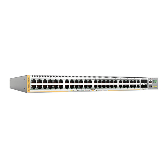
- Page 1 x530DP Series Stackable Multi-Gigabit Layer 3 Ethernet Switches AlliedWare Plus™ x530DP-28GHXm x530DP-52GHXm Quick Installation Guide *613-003073 Rev A* 613-003073 Rev. A...
-
Page 2: Table Of Contents
Gigabit Ethernet switches. For more instructions, refer to the Series Installation Guide for Standalone Switches and x530DP Series Installation Guide for Virtual Chassis Stacking on the Allied Telesis web site at www.alliedtelesis.com/us/en/services-support. This guide contains the following sections: “Front Panels” next ... - Page 3 10/100/1000Mbps Ethernet copper ports with PoE+ 10/100/1000Mbps Ethernet copper ports with PoE++ 100M/1/2.5/5Gbps Ethernet copper ports with PoE++ 1/10Gbps SFP+ transceiver ports Management panel This table lists the Ethernet copper ports on the switches. 10/100/1000M 10/100/1000M 100/1G/2.5G/ Switch PoE+ Copper PoE++ 5G PoE++ Ports...
-
Page 4: Power Supplies And Power Budgets For Poe Devices
Power Supplies and Power Budgets for PoE Devices The power supplies for the switches are purchased separately. Here are the power supplies: PWR150 (AC) PWR250 (AC) PWR250-80 (DC) PWR800 (AC) PWR1200 (AC) The power supplies are installed in the two expansion slots in the rear panel. -
Page 5: Fan10 Module
Note: The PWR150, PWR250, and PWR250-80 Power Supplies do not support PoE. Note: The maximum number of powered devices that the switches can support simultaneously will depend on the power requirements of the devices. FAN10 Module The FAN10 module is the cooling unit of the switch. Here are the guidelines: The module comes pre-installed in the rear panel of the switch. -
Page 6: Beginning The Installation
available in the PDF document “Translated Safety Statements” on the Allied Telesis website at www.alliedtelesis.com/us/en/ documents/translated-safety-statements. Warning: Class 1 Laser product. L1 Warning: Do not stare into the laser beam. L2 Warning: Power cord is used as a disconnection device. - Page 7 Warning: Class I Equipment. This equipment must be earthed. The power plug must be connected to a properly wired earth ground socket outlet. An improperly wired socket outlet could place hazardous voltages on accessible metal parts. Warning: The device is heavy. Always ask for assistance before moving or lifting it to avoid injuring yourself or damaging the equipment.
- Page 8 Unpacking the Switch Here are the items that come with the switch. One 2m (6.6 ft) local management cable with RJ-45 (8P8C) and DB-9 (D-sub 9-pin) connectors Seven square bumper feet Four wall/equipment rack brackets Sixteen 3x6mm screws for attaching the wall/equipment rack brackets to the switch Four 4x32.3mm screws for wood or concrete walls...
- Page 9 Before installing the switch on a table, verify that the table is level and stable. Before installing the switch on a wall, verify that the wall’s material is strong enough to hold the switch’s weight. You should position the device so that it can be screwed into the wall’s framing timber or equivalent structural element.
-
Page 10: Installing The Switch
Installing the Switch Installing Power Supplies To install power supplies, perform the following procedure: 1. Place the switch on a level, secure table. 2. If you are installing the PWR150, PWR250, or PWR250-80 Power Supply, remove the PNL800/1200 Blank Panel from slot B by loosening the two captive screws. - Page 11 America has a 20 Amp, 125 V NEMA 5-20P plug. It requires an NEMA 5-20R receptacle. 5. Slide the new power supply into an expansion slot. Allied Telesis recommends installing the first power supply in slot A. Here are the guidelines: The handle on the power supply should be on the left as you ...
- Page 12 6. Tighten the two captive screws with a cross-head screwdriver to secure the power supply to the switch. 7. If you installed the PWR150, PWR250, PWR250-80, or PWR800 Power Supply, install the power cord retaining clip on the AC plug. Press the sides of the clip inward and insert the two ends into the holes on the AC socket.
- Page 13 9. To install a second power supply, do the following: If slot B is covered with a blank panel, remove the panel. Repeat this procedure, starting with step 3. Installing the Switch on a Desk or Table To install the switch on a desk or table, perform the following procedure: 1.
- Page 14 2. If the bumper feet are attached to the bottom of the switch, remove them using a flat-head screwdriver. 3. Attach two brackets to the sides of the switch with eight bracket screws included with the unit. The following figures illustrate the four possible positions of the brackets on the switch for a standard 19-inch equipment rack.
- Page 15 Installing the Switch on a Wall You can install the switch on a wall with the front panel facing up, left, or right. Do not install the switch with the front panel facing down. Here are the tools and material for installing the switch on a wall: Four wall/equipment rack brackets and sixteen bracket screws ...
- Page 16 Note: If the wall material requires pre-drilled holes, perform steps 4 to 8. Otherwise, go to step 9. 4. Have another person hold the switch on the wall at the selected location for the device while you use a pencil or pen to mark the wall with the locations of the screw holes in the brackets.
-
Page 17: Ports
Ports Ethernet Copper Cable Specifications Here are the minimum cable requirements for the Ethernet copper ports. 10/100Mbps ports: Standard TIA/EIA 568-B-compliant Category 3 unshielded cabling. 1000Mbps ports: Standard TIA/EIA 568-A-compliant Category 5 or TIA/EIA 568-B-compliant Enhanced Category 5 (Cat 5e) unshielded cabling. - Page 18 You can install SFP+ transceivers while the switch is powered on. For a list of supported transceivers, refer to the product’s data sheet on the Allied Telesis web site at www.alliedtelesis.com. The operational specifications and fiber optic cable requirements are included with the transceivers.
-
Page 19: Powering On The Switch
To install SFP+ transceivers, perform the following procedure: 1. To install a transceiver in a top port, position it with the Allied Telesis label facing up. To install it in a bottom port, position it with the label facing down. 2. - Page 20 To power on a switch, perform the following procedure: 1. Raise the retaining clip. (The PWR1200 Power Supply does not have a retaining clip.) 2. Connect the AC power cord to the connector on the power supply. 3. Lower the power cord retaining clips to secure the cord to the switch.
-
Page 21: Leds
4. Connect the power cord to an AC power source. 5. If the switch has two power supplies, repeat this procedure to power on the second power supply. 6. Wait two minutes for the switch to initialize its management software. 7. - Page 22 Solid The port has established a link to another network Amber device, as follows: - Ports 1 to 20 on the x530DP-28GHXm Switch Ports 1 to 40 on the x530DP-52GHXm Switch: Link is 10Mbps or 100Mbps - Ports 21 to 24 on the x530DP-28GHXm Switch Ports 41 to 48 on the x530DP-52GHXm Switch 100Mbps Link is...
-
Page 23: Starting A Local Management Session
SFP+ Port LEDs The SFP+ port LEDs are described here. LED for Top LED for Bottom SFP+ Port SFP+ Port Solid The port has established a 10Gbps link to a network green device. Flashing The port is transmitting or receiving packets at green 10Gbps. -
Page 24: Disabling The Vcstack Feature
If your computer does not have a DB-9 connector, such as laptop computer, Allied Telesis offers the VT-Kit3 management cable for local management sessions. It has a USB-A male connector that connects to a USB port on your computer. The VT-Kit3 management cable and software are sold separately. -
Page 25: Troubleshooting
awplus> enable awplus# configure terminal Enter configuration commands, one per line. End with CNTL/Z. awplus(config)# no stack 1 enable 3. At the confirmation prompt, type Y for yes to disable VCStack, 4. Enter the commands in bold: awplus(config)# exit awplus# write Building configuration ... - Page 26 The information provided herein is subject to change without notice. In no event shall Allied Telesis, Inc. be liable for any incidental, special, indirect, or consequential damages whatsoever, including but not limited to lost profits, arising out of or related to this manual or the information contained herein, even if Allied Telesis, Inc.
Need help?
Do you have a question about the AlliedWare Plus x530DP Series and is the answer not in the manual?
Questions and answers