Table of Contents
Advertisement
Quick Links
Advertisement
Table of Contents

Related Manuals for AXIOMTEK OPS500-520-H Series


Summary of Contents for AXIOMTEK OPS500-520-H Series
- Page 1 OPS500-520-H Series Intel Open Pluggable Specification Box User’s Manual...
-
Page 2: Disclaimers
Axiomtek does not make any commitment to update the information in this manual. Axiomtek reserves the right to change or revise this document and/or product at any time without notice No part of this document may be reproduced, stored in a retrieval system, or transmitted, in any form or by any means, electronic, mechanical, photocopying, recording, or otherwise, without the prior written permission of Axiomtek Co., Ltd. -
Page 3: Safety Approvals
Safety Approvals CE Marking FCC Class A FCC Compliance This equipment has been tested in compliance with the limits for a Class A digital device, pursuant to Part 15 of the FCC Rules. These limits are mean to provide reasonable protection against harmful interference in a residential installation. -
Page 4: Safety Precautions
Safety Precautions Before getting started, please read the following important safety precautions. The OPS500-520-H Series does not come equipped with an operating system. An operating system must be loaded first before installing any software into the computer. Be sure to ground yourself to prevent static charge when installing the internal components. -
Page 5: Table Of Contents
Table of Contents Disclaimers ......................ii Safety Approvals ....................iii Safety Precautions ....................iv CHAPTER 1 INTRODUCTION ................1 General Description ................1 System Specifications ............... 2 1.2.1 Main CPU Board ....................2 1.2.2 I/O System ......................2 Mechanical Assembly ................ 4 1.3.1 Dimensions ....................... - Page 6 3.1.2 CPU FAN Connector (CN3) ................25 3.1.3 M.2 2230 Key E Wi-Fi & Bluetooth (CN4) ............. 25 3.1.4 USB 2.0 Port (CN5) ..................26 3.1.5 USB 3.1 Port (Gen1) (CN6) ................26 3.1.6 Power & Reset Button (CN7) ................ 27 3.1.7 HDMI Connector (CN9) ..................
-
Page 7: Chapter 1 Introduction
Generation Core i series family, which stand for high flexible and user-friendly digital signage applications. Easy maintenance OPS500-520-H Series offers a best solution for digital signage market. Compliant with Intel OPS architecture, digital signage players are capable of deploying interchangeable systems faster and easing upgrading/maintenance, while lowering costs for development and implementation. -
Page 8: System Specifications
OPS500-520-H User’s Manual System Specifications 1.2.1 Main CPU Board ® Core™ i7/i5/i3/Celeron Processors, LGA1151, 35W TDP Gen. Intel System Chipset ® Intel H310 PCH BIOS American Megatrends Inc. UEFI (Unified Extensible Firmware Interface) . ... - Page 9 OPS500-520-H User’s Manual Storage One M.2 Key M 2280 for SATA SSD Antenna opening Two Antenna openings in the front I/O side Net Weight 0.9kg(1.99 lb) without cooler Dimension (Main Body Size) 200 mm x 119 mm(D) x 30 mm(H) ...
-
Page 10: Mechanical Assembly
30mm, and it shows the location of the screw holes of front panel as well as the security lock. ※W hile plugging the OPS module, please make sure the heat sink side of OPS module toward the outside. Axiomtek will be out of reasonability if there is any damage occurred due to it. -
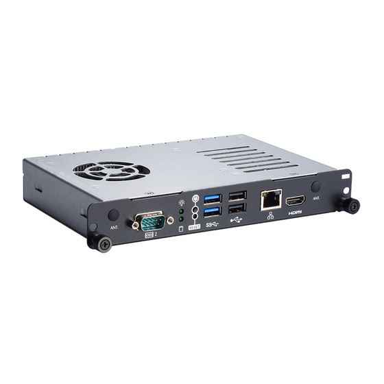
Page 11: I/O Outlet
OPS500-520-H User’s Manual 1.3.2 I/O outlet The following figures show you the locations of the OPS500-520-H Series I/O outlets. 1.3.3 Mechanical Specifications OPS500-520-H Series is docked in the reference display panel The OPS500-520-H Pluggable Module docked at a display panel system. - Page 12 OPS500-520-H User’s Manual Exploded View of the Pluggable Module Introduction...
- Page 13 The Guide Rail Mechanism for the OPS500-520-H Series Module You can use the rails alongside of OPS500-520-H Series Module to dock and undock the plug connector at the back of the module to connect with docking board. There are two lock pins on each side of the rail, and they serve as the locking mechanism to attach the lock holes on the series module.
- Page 14 OPS500-520-H User’s Manual Location of Lock Hole on the Pluggable Module *The drawing is base on Intel Open Pluggable Specification Introduction...
- Page 15 OPS500-520-H User’s Manual Dimensions of the Guide Rail Introduction...
- Page 16 Vent Holes at the Pluggable Module Back Panel On the OPS500-520-H Series module, it is recommended by Intel that some vent holes be opened at the back so that hot air can escape more easily from the module that the FAR in on both sides of the module back panel should be greater than 0.25.
-
Page 17: Reference Design
Reference Design Display Panel Rear View – Internal The digital signage OPS500-520-H Series prototype is based on a 32” display panel with the functional blocks illustrated. It is mainly a 3 -board partitioning design consisting of the pluggable module, docking board and the panel control board. -
Page 18: Package List
Thermal Grease (Syringe 1G) x 1 M.2 Thermal Pad x 1 M3*4L screw x 2 M4*6L screw x 2 If you cannot find the package or any items are missing, please contact Axiomtek distributors immediately. Introduction... -
Page 19: Chapter 2 Hardware Installation
Pluggable Module Method DRAM, Storage, Wireless module Installations The OPS500-520-H Series model offers a convenient drive bay module for users to DDR4 SO-DIMM DRAM, M.2 2280 Key M SSD Storage and wireless modules. Please follow the steps as below: 2.1.1... -
Page 20: Ddr4 So-Dimm Dram Installation (So-Dimm 2)
OPS500-520-H User’s Manual Step 3 Place the memory module into the socket and press it firmly. The socket latches are levered upwards and clipped on to the edges of the SO- DIMM. 2.1.2 DDR4 SO-DIMM DRAM Installation (SO-DIMM 2) Step 1 Locate screws at the chassis as red marked and loosen four screws. - Page 21 OPS500-520-H User’s Manual Step 3 Place the memory module into the socket and press it firmly. The socket latches are levered upwards and clipped on to the edges of the SO-DIMM. Hardware Installation...
-
Page 22: 2.1.3 M.2 Ssd Installation
OPS500-520-H User’s Manual 2.1.3 M.2 SSD Installation The OPS500-520-H Series provides one M.2 Key M 2280 socket to install M.2 SSD. Please refer to the following instructions and illustration. Step 1 Turn the system upside down to locate screws at the chassis as red marked and loosen five screws. -
Page 23: Wireless Module (M.2 Key E Card)
OPS500-520-H User’s Manual 2.1.4 Wireless Module (M.2 Key E Card) The OPS500-520-H Series provides one M.2 Key E Socket for user to install M.2 Key E Card, please refer to the following instructions and illustration. Step 1 Locate screws at the chassis as red marked and loosen four screws. - Page 24 OPS500-520-H User’s Manual Step 3 Locate the M.2 2230 Key E slot on the board. And holding the M.2 2230 Key E card at a 30 degree angle up from horizontal, slowly insert the golden fingers into the M.2 2230 Key E slot until it is fully inserted in. Step 4 Then secure the M.2 2230 Key E Wi-Fi Module to the carrier by tightening up the one M3*4L pan head screw to the marked position.
-
Page 25: Pluggble Module Method
Step 1 Pluggable the box into display Caution: When plugging OPS500-520-H Series module into an OPS display, make sure the module’s heat sink is facing outside of the display. Axiomtek is not responsible for any damage caused by wrong installation Step 2 Fasten the screws as illustrated. - Page 26 OPS500-520-H User’s Manual This page is intentionally left blank. Hardware Installation...
-
Page 27: Chapter 3 Connectors
OPS500-520-H User’s Manual CHAPTER 3 CONNECTORS This chapter provides users with detailed description how to set up basic system configuration through the AMIBIOS8 BIOS setup utility. Connectors Connectors connect this board with other parts of the system. Loose or improper connection might cause problems. - Page 28 OPS500-520-H User’s Manual Board Layout Top side Connectors...
- Page 29 OPS500-520-H User’s Manual Bottom side Connectors...
-
Page 30: Jae Tx25A Connector (Cn1)
OPS500-520-H User’s Manual 3.1.1 JAE TX25A Connector (CN1) Connector JAE TX25A CN1 is for JAE improced interface supported. Pin Signal Pin Signal Pin Signal Pin Signal DDP_3N DDP_3P 3 GND 4 DDP_2N DDP_2P 7 DDP_1N 8 DDP_1P 10 DDP_0N 11 DDP_0P 12 GND 13 DDP_AUXN 14 DDP_AUXP... -
Page 31: Cpu Fan Connector (Cn3)
OPS500-520-H User’s Manual 3.1.2 CPU FAN Connector (CN3) CN3 provides power input and FAN control signal, and you can connect CPU FAN through this connector. Signal FAN CTRL FAN DET 3.1.3 M.2 2230 Key E Wi-Fi & Bluetooth (CN4) CN4 for PCI-Express and USB signals interface supported Socket 1,Key E,type 2230. Signal Signal Signal... -
Page 32: Usb 2.0 Port (Cn5)
OPS500-520-H User’s Manual 3.1.4 USB 2.0 Port (CN5) The Universal Serial Bus connectors are compliant with USB 2.0 (480Mbps), and ideally for installing USB peripherals such as keyboard, mouse, scanner, etc. Signal USB_POWER USB D0- USB D0+ USB_POWER USB D1- USB D1+ 3.1.5 USB 3.1 Port (Gen1) (CN6) -
Page 33: Power & Reset Button (Cn7)
OPS500-520-H User’s Manual 3.1.6 Power & Reset Button (CN7) The CN7 comes with one power button and one reset button. The reset button is for rebooting your computer instead of turning OFF the power switch. It is a better way to reboot your system for a longer life of the system’s power supply. -
Page 34: 2280 Key M Ssd (Scn1)
OPS500-520-H User’s Manual 3.1.9 M.2 2280 Key M SSD (SCN1) The OPS500-520-H comes with one M.2 2280 Key SSD for storage. Signal Signal Signal Signal +3.3V +3.3V LED_1# +3.3V +3.3V +3.3V +3.3V SATA-B+ SATA-B- SATA-A- SATA-A+ CONNECTOR CONNECTOR Key M Key M CONNECTOR CONNECTOR... -
Page 35: Com Port (Com2)
OPS500-520-H User’s Manual 3.1.10 COM Port (COM2) The COM Port connector (COM2) is a standard DB-9 connector. The pin assignment of RS- 232 is listed on the following table Signal DCD, Data carrier detect RXD, Receive data TXD, Transmit data DTR, Data terminal ready GND, ground DSR, Data set ready... -
Page 36: 3.1.13 Sw1 Setting
OPS500-520-H User’s Manual 3.1.13 SW1 Setting ATX/AT Mode and CMOS Clear can be set through SW1. Description OFF (Default) AT / ATX Mode CMOS Clear Clear CMOS Normal Power LED The Power LED lights up when the system is powered ON Storage Activity LED This connection is linked to hard drive activity LED on the control panel. -
Page 37: Chapter 4 Ami Bios Setup Utility
OPS500-520-H User’s Manual CHAPTER 4 AMI BIOS SETUP UTILITY This chapter provides users with detailed description how to set up basic system configuration through the AMIBIOS8 BIOS setup utility. Starting To enter the setup screens, follow the steps below: Turn on the computer and press the <Del>... -
Page 38: Main Menu
OPS500-520-H User’s Manual Main Menu When you first enter the Setup Utility, you will enter the Main setup screen. You can always return to the Main setup screen by selecting the Main tab. There are two Main Setup options. They are described in this section. The Main BIOS Setup screen is shown below. ... -
Page 39: Advanced Menu
OPS500-520-H User’s Manual Advanced Menu The Advanced menu also allows users to set configuration of the CPU and other system devices. You can select any of the items in the left frame of the screen to go to the sub menus: ... - Page 40 OPS500-520-H User’s Manual F81803 Super IO Configuration Set parameters of Serial Port 1(COM1)/Serial Port 2(COM2) Serial Port Enable or Disable serial port. Device Settings Display the serial port resource. AMI BIOS Setup Utility...
- Page 41 OPS500-520-H User’s Manual ACPI Settings You can use this screen to select options for the ACPI Configuration, and change the value of the selected option. A description of the selected item appears on the right side of the screen. ...
- Page 42 OPS500-520-H User’s Manual Trusted Computing This screen provides function for specifying the TPM(Trusted Platform Module) settings. Security Device Support Use this item to enable or disable TPM(Trusted Platform Module) function. AMI BIOS Setup Utility...
- Page 43 OPS500-520-H User’s Manual CPU Configuration This screen shows the CPU Configuration, and you can change the value of the selected option. Hyper Threading select Hyper-threading function which Intel's proprietary simultaneous multithreading (SMT) implementation used to improve parallelization of computations (doing multiple tasks at once) performed on x86 microprocessors.
- Page 44 OPS500-520-H User’s Manual SATA And RST Configuration You can use this screen to select options for the SATA And RST Configuration, and change the value of the selected option. A description of the selected item appears on the right side of the screen.
- Page 45 OPS500-520-H User’s Manual PCH-FW Configuration You can use this screen to confirm ME Firmware version. AMI BIOS Setup Utility...
- Page 46 OPS500-520-H User’s Manual CSM Configuration Configure settings associated with the CSM (Compatibility Support Module), such as Option ROM execution. Boot option filiter This option controls Legacy/UEFI ROMs priority. Launch PXE OpROM policy Specifies which PXE Option ROM will be started. For PXE boot there is available the normal (Legacy) PXE boot as well as a UEFI PXE boot.
- Page 47 OPS500-520-H User’s Manual Hardware Monitor This screen shows the Hardware Configuration, and enable or disable smart fan. Smart Fan Function Enable or Disable Smart Fan. AMI BIOS Setup Utility...
-
Page 48: Chipset Menu
OPS500-520-H User’s Manual Chipset Menu The Chipset menu allows users to change the advanced chipset settings. You can select any of the items in the left frame of the screen to go to the sub menus: System Agent (SA) Configuration ... - Page 49 OPS500-520-H User’s Manual System Agent (SA) Configuration To adjust graphics and memory detail configurations. Graphics Configuration Graphics configuration parameters. Memory Configuration Memory configuration parameters. AMI BIOS Setup Utility...
- Page 50 OPS500-520-H User’s Manual Graphics Configuration This option allows the user to view the Graphics Configuration parameters, such as Intel Internal Graphics (IGFx) Video BIOS Version. AMI BIOS Setup Utility...
- Page 51 OPS500-520-H User’s Manual Memory Information This screen shows the system memory information. AMI BIOS Setup Utility...
- Page 52 OPS500-520-H User’s Manual PCH–IO Configuration This screen allows users to set PCH parameters. PCH LAN Controller Enable or disable PCH LAN controller. Wake on LAN Enable or disable Wake on LAN functionality. AMI BIOS Setup Utility...
-
Page 53: Boot Menu
OPS500-520-H User’s Manual Boot Menu The Boot menu allows users to change boot options of the system. You can select any of the items in the left frame of the screen to go to the sub menus: Setup Prompt Timeout ... -
Page 54: Security Menu
OPS500-520-H User’s Manual Security Menu The Security menu allows users to change the security settings for the system. Administrator Password This item indicates whether an administrator password has been set. If the Administrator password is set, BIOS will ask and wait for administrator password entered. -
Page 55: Save & Exit Menu
OPS500-520-H User’s Manual Save & Exit Menu The Save & Exit menu allows users to load your system configuration with optimal or failsafe default values. Save Changes and Exit When you have completed the system configuration changes, select Save Changes and Exit from the Save &... - Page 56 OPS500-520-H User’s Manual Discard Changes and Reset Select this option to quit Setup without making any permanent changes to the system configuration and reboot the computer. Select Discard Changes and Reset from the Save & Exit menu and press <Enter>. Select Yes to discard changes and reset. ...
-
Page 57: Appendix Awatchdog Timer
OPS500-520-H User’s Manual APPENDIX A WATCHDOG TIMER Watchdog Timer Setting After the system stops working for a while, it can be auto-reset by the W atchdog Timer. The integrated Watchdog Timer can be set up in the system reset mode by program. - Page 58 OPS500-520-H User’s Manual This page is intentionally left blank. Watchdog Timer...
Need help?
Do you have a question about the OPS500-520-H Series and is the answer not in the manual?
Questions and answers