Table of Contents
Advertisement
Quick Links
Advertisement
Table of Contents

Related Manuals for GeoMax Zone60 DG


Summary of Contents for GeoMax Zone60 DG
- Page 1 GeoMax Zone60 DG User Manual Version 2.1 English...
- Page 2 Always refer to this information when you need to contact your agency or GeoMax authorised service centre. Validity of this manual This manual applies to the Zone60 DG lasers. Differences between the models are marked and described. Available documentation Name...
-
Page 3: Table Of Contents
Alignment of the Axes Precise Alignment of the Axes Laydown Operation ZRC60 Remote Control Description of the Remote Control Pairing the Zone60 DG with the ZRC60 Remote Control Connecting Screens for the Remote Control Receivers Overview 5.1.1 ZRB35, Basic Receiver 5.1.2... - Page 4 Accuracy Adjustment 10.1 hecking the Level Accuracy 10.2 Adjusting the Self-Levelling Accuracy 10.3 Adjusting the Vertical Accuracy Troubleshooting Care and Transport 12.1 Transport 12.2 Storage 12.3 Cleaning and Drying Technical Data 13.1 Conformity to National Regulations 13.2 Dangerous Goods Regulations 13.3 General Technical Data of the Product 13.3.1...
-
Page 5: Safety Directions
Safety Directions General Description The following directions enable the person responsible for the product, and the person who actu- ally uses the equipment, to anticipate and avoid operational hazards. The person responsible for the product must ensure that all users understand these directions and adhere to them. -
Page 6: Limits Of Use
Responsibilities Manufacturer of the GeoMax AG, CH-9443 Widnau, hereinafter referred to as GeoMax, is responsible for supplying product the product, including the user manual and original accessories, in a safe condition. Person responsible for the... - Page 7 DANGER Risk of electrocution Because of the risk of electrocution, it is dangerous to use poles, levelling staffs and extensions in the vicinity of electrical installations such as power cables or electrical railways. Precautions: ▶ Keep at a safe distance from electrical installations. If it is essential to work in this environ- ment, first contact the safety authorities responsible for the electrical installations and fol- low their instructions.
- Page 8 ▶ Do not open the product! ▶ Only GeoMax authorised service centres are entitled to repair these products. WARNING If the product is improperly disposed of, the following can happen: If polymer parts are burnt, poisonous gases are produced which may impair health.
- Page 9 Using the product after incorrect attempts were made to carry out repairs. • Precautions: ▶ Do not open the product! ▶ Only GeoMax authorised service centres are entitled to repair these products. WARNING Short circuit of battery Risk of fire, electric shock and damage. Precautions: ▶...
-
Page 10: Laser Classification
National laws and local regulations could impose more stringent instructions for the safe use of lasers than IEC 60825-1 (2014-05) and IEC TR 60825-14 (2004-02). 1.6.2 Zone60 DG General The rotating laser built into the product produces a visible laser beam which emerges from the rotating head. -
Page 11: Electromagnetic Compatibility (Emc)
Precautions: ▶ Although the product meets the strict regulations and standards which are in force in this respect, GeoMax cannot completely exclude the possibility that other equipment may be disturbed. CAUTION Use of the product with accessories from other manufacturers. For example field com-... -
Page 12: Fcc Statement, Applicable In U
Although the product meets the strict regulations and standards which are in force in this respect, GeoMax cannot completely exclude the possibility that function of the product may be disturbed in such an electromagnetic environment. - Page 13 Consult the dealer or an experienced radio/TV technician for help. • CAUTION Changes or modifications not expressly approved by GeoMax for compliance could void the user's authority to operate the equipment. Labelling Zone60 DG GeoMax AG CH-9443 Widnau Complies with 21 CFR 1040.10 and...
- Page 14 Labelling receiver ZRB35 Model: ZRB35 Art.No.: 835246 Power: 9V / 0.2A GeoMax AG CH-9443 Widnau Made in China Manufactured: MM/YYYY S.No.: 1234567 This device complies with part 15 of the FCC Rules. Operation is subject to the following two conditions:...
- Page 15 Power : 3V / 180mA Art.No.: 835245 Made in China GeoMax AG CH-9443 Widnau Contains FCC ID: RFD-CT301 IC ID: 3177A-CT301 This device complies with part 15 of the FCC Rules. Operation is subject to the following two conditions: (1) This device may not cause harmful interference, and (2) this device must accept any interference received, including interference that may cause undesired operation.
-
Page 16: Description Of The System
Once the Zone60 DG has levelled, the head starts rotating and the Zone60 DG is ready for use. 30 seconds after the Zone60 DG has completed the levelling, the H.I.Alert system becomes act- ive and protects the Zone60 DG against changes in elevation caused by movement of the tripod to ensure accurate work. -
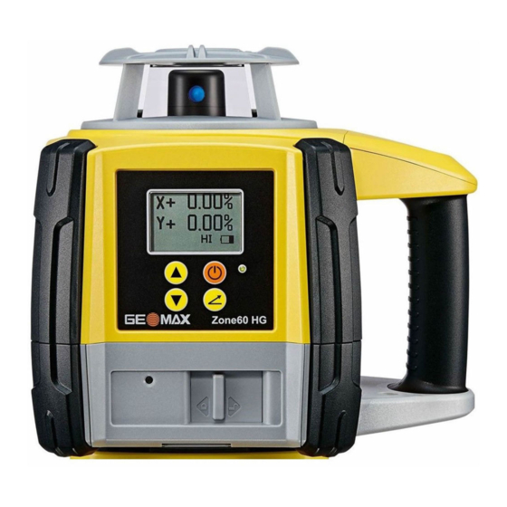
Page 17: Zone60 Dg Laser Components
Zone60 DG Laser Components Zone60 DG laser compon- ents Plate for optional scope Carry Handle LCD Display Control Panel Battery compart- ment Charge LED (for Li- Ion battery pack) 011232_001 Case Components Case components 011213_001 Zone60 DG laser Charger (for Li-Ion versions only) -
Page 18: Setup
011214_001 Set up the tripod. Place the Zone60 DG on the tripod. Tighten the screw on the underside of the tripod to secure the Zone60 DG on the tri- pod. ☞ Attach the Zone60 DG securely to a tripod or laser trailer, or mount on a stable •... -
Page 19: Operation
The LCD display turns on and displays the current status of the Zone60 DG. • If set up within the +/-6° self-levelling range (horizontal or vertical), the Zone60 DG auto- • matically levels to create an accurate horizontal plane of laser light. -
Page 20: Grade Entry
To change the grade value, press the Up or Down Arrow buttons. To exit grade entry mode, press the Grade button until the main display is shown. Wait for 8 seconds. The Zone60 DG automatically returns to the main display. Grade entry by digit While in grade entry mode, you can easily change the plus/minus sign or individual digits. - Page 21 Up/Menu button and Down/Sleep button simultaneously. Grade capability The Zone60 DG can have up to 10.00% grade simultaneously in both the X and Y axes or up to 15.00% grade in one axis. Entering grades above 10.00% in one axis is only possible if the cross axis grade is ±3% or lower.
-
Page 22: Axis Identification
Example: The Zone60 DG is set up on the crown of the road and one axis is aligned to the centreline. In order to make the cross axis grade fall to the right or left hand side, simply change the plus/minus sign on the Combo grade screen. -
Page 23: Precise Alignment Of The Axes
Precise Alignment of the Axes Precisely aligning X- and Under most conditions, the raised alignment marks on the top of the Zone60 DG are adequate Y-axis for alignment of the axes. For a more precise alignment, you can use the following procedure. -
Page 24: Laydown Operation
It is recommended that you first perform the pre- cise alignment procedure, and then adjust the scope to these axes. Laydown Operation Vertical plane of laser You can use the Zone60 DG in laying down position to create a vertical plane for layout and light alignment jobs. 007597_001... -
Page 25: Zrc60 Remote Control
ZRC60 Remote Control Description of the Remote Control The RF Remote Control communicates with the Zone60 DG via RF (radio frequency) and is used to control the same functions as on the laser. ZRC60 Remote Control LCD display Power button... -
Page 26: Pairing The Zone60 Dg With The Zrc60 Remote Control
Zone60 DG remotely up to 300 m (1000’) from the Zone60 DG. Before using the RF features, the Zone60 DG and the remote control must be paired together to be able to communicate with each other. -
Page 27: Connecting Screens For The Remote Control
Zone60 DG. 007598_001 007599_001 Lost communication screen The “lost communication” screen is dis- played when the Zone60 DG and the remote control have lost their communica- tion link. ☞ Ensure that you are within clear sight of the Zone60 DG and that you have not exceeded the working range. -
Page 28: Receivers
Receivers Overview Description The Zone60 DG is sold with either the ZRP105, ZRD105 or the ZRD105B receiver. The ZRD105B receiver enhances the performance of the Zone60 DG with automatic Beam Catching and monit- oring. 5.1.1 ZRB35, Basic Receiver Instrument components... -
Page 29: Zrp105, Pro Receiver
Description of the buttons 011192_001 Audio Bandwidth Power Button Function Audio Press to change the audio output. Bandwidth Press to change detection bandwidth. Power Press once to turn on the Receiver. 5.1.2 ZRP105, Pro Receiver Instrument components part 1 of 2 Level vial Audio speaker LCD window... -
Page 30: Zrd105, Digital Receiver
Component Description Keypad Power, accuracy and volume functions. Instrument components part 2 of 2 Bracket mounting hole Offset notch Product label Battery door 011194_001 Component Description Bracket mounting hole Location to attach the receiver bracket for normal operation. Offset notch Use to transfer reference marks. -
Page 31: Zrd105B, Digital Rf Receiver
Press to change the audio output. 5.1.4 ZRD105B, Digital RF Receiver The ZRD105B receiver provides you with basic position information by using an arrow display, digital readout plus RF communication to the Zone60 DG for special features. Instrument components Speaker LCD Digital Display... -
Page 32: Using The Zrd105B Receiver With The Zone60 Dg
The Zone60 DG and the ZRD105B Receiver include radio devices that allow you to activate the functions on the Zone60 DG remotely up to 100 m (300’) from the Zone60 DG. Before using the RF features, the Zone60 DG and the Receiver must be paired together to be able to communicate with each other. -
Page 33: Zone60 Dg Menu
Access and Navigation Description The Zone60 DG has several menu options that allow you to optimise the performance of the Zone60 DG for an individual application. To access the menu of the Zone60 DG, press the Left and Right arrow buttons simultaneously while the main screen is displayed. -
Page 34: Menu Set
The Height of Instrument (H.I.) or Elevation Alert function prevents incorrect work caused by movement or settling of the tripod that would cause the laser to level at a lower height. 30 seconds after the Zone60 DG has levelled and the head of the laser starts rotating, the H.I.Alert function becomes active. - Page 35 Manual mode with grade • You can choose to disable the automatic self-levelling mode. ☞ The Zone60 DG always turns on in automatic mode regardless of the previous selec- tion. 007611_001 Automatic mode The Zone60 DG always turns on in automatic mode and continuously self-levels to maintain grade accuracy.
- Page 36 When using this mode, the Zone60 DG first levels to the selected grade, then returns to manual mode. 007615_001 007616_001 Manual mode with grade - X- Manual mode with grade- Y- axis axis 007613_001 007614_001 Manual grade entry - X-axis...
-
Page 37: Menu Set
To exit the menu, highlight and select the EXIT icon. OR: Wait for 8 seconds and the menu is exited auto- matically. ☞ 007621_001 To display the Menu Set 3, highlight and select the MENU 3 icon. Menu Set 2 Zone60 DG Menu... - Page 38 Normally, the beam masking setting is disabled every time you power off turn off the Zone60 DG. If you prefer to save the beam masking settings for usage on the following day, you can enable the saving of the beam masking setting: Save: The beam masking settings are saved at power off.
- Page 39 007626_001 Temperature check set- tings screens Relevelling process When the Zone60 DG is relevelling, the Temperature check wait screen is displayed. Wait until the process is finished before using the laser again. The Status LED flashes to indicate normal levelling.
- Page 40 Negative grade screens Radio - enable/disable To be able to communicate with the ZRC60 remote control and the receiver, the radio on the Zone60 DG must be enabled. The radio is automatically enabled when the units are paired together. ON: Radio is enabled.
- Page 41 Customer name settings The Customer name settings allow you to enter the name of the customer, to enable/disable the customer name screen when turning on the Zone60 DG, and to protect the name entry with a password. Customer name entry When entering the Customer Name settings the first time, you are taken directly to the Customer Name entry screen.
- Page 42 • 007639_001 007640_001 Display percent Display per mil Standard usage is percent of grade. You are asked to confirm the selected option to prevent unwanted changes and possible errors due to the shift of the decimal point. Zone60 DG Menu...
- Page 43 Normally, the grade value is reset to 0.000% every time you turn on the Zone60 DG. power up If you prefer to display the previous grade settings when turning on the Zone60 DG, you can enable the option Show Grade.
- Page 44 The hours can be set in increments of 40 hours. 007647_001 Set Calibration Alert Hours Screen Display of Calibration Alert on Start-up Screen If you enabled the calibration alert function, the calibration alert hours are displayed on the start-up screen after turning on the Zone60 DG: Zone60 DG Menu...
- Page 45 When the number of planned hours is reached, the words “CALIBRATION ALERT” are displayed for 8 seconds. After calibrating the Zone60 DG, the calibration alert hours are automatically reset. Changing or disabling the calibration alert is only possible by accessing the menu option “Calibration alert activation”.
-
Page 46: Zrc60 Menu
Use the Up and Down arrow buttons to adjust the brightness as desired. 007651_001 Remote control display brightness Sleep mode hours You can determine how long the Zone60 DG stays in sleep mode before turning off completely: 2 hours • 4 hours •... -
Page 47: Applications
Set up the tripod on a stable surface outside the working area. Turn on the Zone60 DG. Enter the required grade on the Zone60 DG. Refer to "3.4 Grade Entry". Attach the receiver on the mast that is mounted on the machine. -
Page 48: Entering Grades
Press the Grade button to enter grade for the Y-axis. Press the Grade button again to exit grade entry mode. Once grade is entered, the Zone60 DG will begin to adjust to grade. Do not disturb the Zone60 DG during this process. -
Page 49: Beam Catching (Grade Matching)
Beam Catching (Grade Matching) Beam Catching using the Using the Beam Catching feature you can match an existing grade. The Zone60 DG moves to the ZRD105B new grade position, displays the grade found and begins self-levelling to maintain the grade over step-by-step time. - Page 50 The Beam Lock process can only be run on the X-axis in horizontal mode. Ensure that the grade value is set to zero. Set up the Zone60 DG at the base of a slope with the X-axis pointing in the direction of the slope.
-
Page 51: Batteries
Connect the charger plug into the charge jack on the Zone60 DG battery pack. The small LED next to the charge jack flashes indicating that the Zone60 DG is char- ging. The LED is on solid when the battery pack is fully charged. - Page 52 Changing the alkaline bat- With alkaline batteries the battery indicator on the Zone60 DG LCD display flashes when the bat- teries step-by-step teries are low and need to be replaced. If no battery icon is shown, the batteries are okay.
- Page 53 Step Description ☞ The batteries are inserted in the front of the laser. Slide the locking mechanism on the battery compartment to the right and open the cover of the battery compartment. To remove the batteries: Remove the batteries from the battery compartment. To insert the batteries: Insert the batteries into the battery compartment, ensuring that the contacts are facing in the right direction.
-
Page 54: Accuracy Adjustment
30 m (100 ft) X— 011292_001 Align the first axis so that it is square to a wall. Allow the Zone60 DG to self-level completely (approximately 1 minute after the Zone60 DG begins to rotate). Mark the position of the beam. -
Page 55: Adjusting The Self-Levelling Accuracy
Put the Zone60 DG in an upright position. Press and hold both the Up and Down arrow buttons. Press the Power button. The X-axis calibration screen appears. The Zone60 DG is now in calibration mode. ☞ In calibration mode, the LED does not blink and the laser head continues to rotate. -
Page 56: Adjusting The Vertical Accuracy
After calibration of the X-axis, the Y-axis calibration screen appears: step-by-step 007734_001 When the hour glass has disappeared, indicating that the Zone60 DG has levelled, check both sides of the Y-axis. Press the Up and Down arrow buttons to bring the plane of laser light to the spe- cified level position. - Page 57 Press and hold the Grade button for 3 seconds to accept the adjusted position, to save and store the calibration settings and to return to the main user screen. Accuracy Adjustment...
-
Page 58: Troubleshooting
2 minutes in the alert condi- tion, the unit will shut off auto- matically. 007748_001 Temperature Alert The Zone60 DG is in an envir- The Temperature Alert screen onment where it cannot oper- is shown. ate without damaging the laser... - Page 59 Refer to " Negative grade - enable/disable". 007750_001 The “empty battery” icon The Zone60 DG has reached a flashes. low battery condition and changes the head speed to 7rps. If the receiver detects the Zone60 DG rotating at 7 rps, it displays a small flash- ing Zone60 DG.
- Page 60 Dirt is reducing the laser Clean the windows of the Zone60 is reduced. output. DG and the receiver. If the problem continues, return the Zone60 DG to an authorised service centre for service. The laser receiver is not The Zone60 DG is not Check for proper operation of the working properly.
-
Page 61: Care And Transport
For products for which no container is available use the original packaging or its equivalent. Shipping When transporting the product by rail, air or sea, always use the complete original GeoMax pack- aging, container and cardboard box, or its equivalent, to protect against shock and vibration. - Page 62 Damp products Dry the product, the transport container, the foam inserts and the accessories at a temperature not greater than 40°C /104°F and clean them. Remove the battery cover and dry the battery compartment. Do not repack until everything is completely dry. Always close the transport con- tainer when using in the field.
-
Page 63: Technical Data
FCC Part 15 (applicable in US) • regulations Hereby, GeoMax AG declares that the radio equipment type Zone60 DG is in compliance • with Directive 2014/53/EU and other applicable European Directives. The full text of the EU declaration of conformity is available at the following Internet address: www.geomax-positioning.com/Downloads.htm. - Page 64 202 mm (8.0") 011229_001 Grade Capability ± 10% in both axes simultaneously, 15% in one axis with up to 3% in the cross axis Weight Zone60 DG weight with battery: 3.4 kg/7.4 lbs. Internal battery Type Operating times* at 20°C...
-
Page 65: Zrc60 Remote Control
Lithium-Ion charger Type Value Input voltage 100 V AC-240 V AC, 50 Hz-60 Hz Output voltage 12 V DC Output current 3.0 A Polarity Shaft: negative, Tip: positive Lithium-Ion battery pack Type Value Input voltage 12 V DC Input current 2.5 A Charge time 5 hours (maximum) at 20 °C... - Page 66 841553-2.1.0en Original text © 2019 GeoMax AG (Widnau, Switzerland) is part of Hexagon AB. All rights reserved. GeoMax AG geomax-positioning.com...
Need help?
Do you have a question about the Zone60 DG and is the answer not in the manual?
Questions and answers