Table of Contents
Advertisement
Quick Links
Advertisement
Table of Contents

Related Manuals for GeoMax Zone60 DG


Summary of Contents for GeoMax Zone60 DG
- Page 1 GeoMax Zone60 DG User Manual Version 2.0 English...
- Page 2 Always refer to this information when you need to contact your agency or GeoMax authorised service centre. Validity of this manual This manual applies to the Zone60 DG lasers. Differences between the models are marked and described. Available Name Description/Format...
-
Page 3: Table Of Contents
Conversion of Slope Into Percent of Grade Alignment of the Axes Precise Alignment of the Axes Laydown Operation ZRC60 Remote Control Description of the Remote Control Pairing the Zone60 DG with the ZRC60 Remote Control Connecting Screens for the Remote Control Receivers Overview 5.1.1 ZRB35 Receiver 5.1.2... - Page 4 Care and Transport 12.1 Transport 12.2 Storage 12.3 Cleaning and Drying Technical Data 13.1 Conformity to National Regulations 13.2 Dangerous Goods Regulations 13.3 General Technical Data of the Laser 13.3.1 ZRC60 Remote Control Zone60 DG | 4 Table of Contents...
-
Page 5: Safety Directions
• Use after misappropriation. • Use of products with obvious damages or defects. • Use with accessories from other manufacturers without the prior explicit approval of GeoMax. • Inadequate safeguards at the working site. • Deliberate dazzling of third parties. -
Page 6: Limits Of Use
Responsibilities Manufacturer of the GeoMax AG, CH-9443 Widnau, hereinafter referred to as GeoMax, is responsible for supplying the product, product including the user manual and original accessories, in a safe condition. - Page 7 Using the product after incorrect attempts were made to carry out repairs Precautions: Do not open the product. Only GeoMax authorised service centres are entitled to repair these products. If the product is improperly disposed of, the following can happen: WARNING •...
-
Page 8: Laser Classification
0.4 mW / 2.2 mW Pulse duration (effective) 500 ms / 2.9 ms, 1.4 ms Pulse repetition frequency 1 Hz / 5 Hz, 10 Hz Beam divergence 0.2 mrad Wavelength 635 nm Labelling 011205_001 a) Laser beam Zone60 DG | 8 Safety Directions... -
Page 9: Electromagnetic Compatibility Emc
Electromagnetic radiation can cause disturbances in other equipment. WARNING Although the product meets the strict regulations and standards which are in force in this respect, GeoMax cannot completely exclude the possibility that other equipment may be disturbed. There is a risk that disturbances may be caused in other equipment if the product is used with accessories... -
Page 10: Fcc Statement, Applicable In U
Connect the equipment into an outlet on a circuit different from that to which the receiver is connected. • Consult the dealer or an experienced radio/TV technician for help. Changes or modifications not expressly approved by GeoMax for compliance could void the user's authority WARNING to operate the equipment. - Page 11 This device complies with part 15 of the FCC Rules. Operation is subject to the following two conditions: (1) This device may not cause harmful interference, and (2) this device must accept any interference received, including interference that may cause undesired operation. 011208_001 Zone60 DG | 11 Safety Directions...
-
Page 12: Description Of The System
Once the Zone60 DG has levelled, the head starts rotating and the Zone60 DG is ready for use. 30 seconds after the Zone60 DG has completed the levelling, the H.I.Alert system becomes active and protects the Zone60 DG against changes in elevation caused by movement of the tripod to ensure accurate work. -
Page 13: Zone60 Dg Laser Components
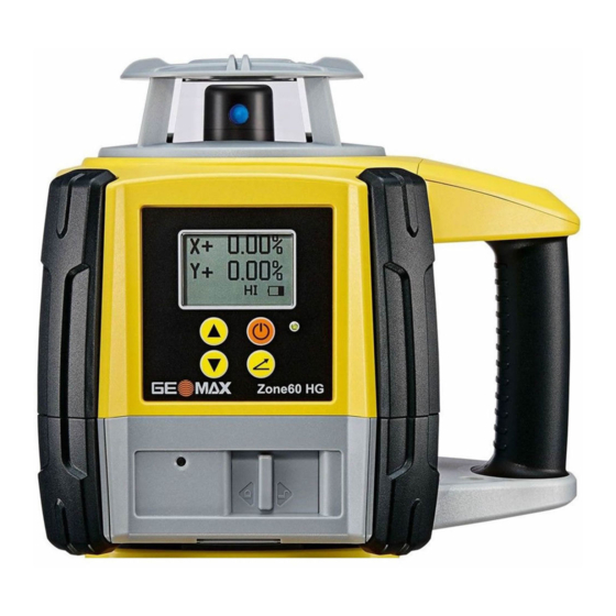
Zone60 DG Laser Components Zone60 DG laser compo- nents a) Plate for optional scope b) Carry Handle c) LCD Display d) Control Panel e) Battery compartment Charge LED (for Li-Ion battery pack) 011232_001 Case Components Case components 011213_001 a) Zone60 DG laser... -
Page 14: Setup
Place the Zone60 DG on a stable ground. Ground vibration and extremely windy conditions can affect the operation of the Zone60 DG. • When working in a very dusty environment place the Zone60 DG up-wind so the dirt is blown away from the laser. Setting up on a tripod... -
Page 15: Operation
The LCD display turns on and displays the current status of the Zone60 DG. • If set up within the +/-6° self-levelling range (horizontal or vertical), the Zone60 DG automatically levels to create an accurate horizontal plane of laser light. -
Page 16: The Lcd Display
The LCD Display Main Display The LCD display shows all the information that is required to operate the Zone60 DG. a) X-axis Grade Value b) Y-axis Grade Value c) Beam Masking d) Radio Indication e) Battery Level Indication H.I. Indication... - Page 17 Down Arrow Buttons simultaneously. Grade Capability The Zone60 DG can have up to 10.00% grade simultaneously in both the X and Y axes or up to 15.00% grade in one axis. Entering grades above 10.00% in one axis is only possible if the cross axis grade is ±3% or lower.
-
Page 18: Axis Identification
Ensure that the Zone60 DG is properly positioned over a control point. The direction of the X-Axis is seen from the front of the Zone60 DG, sighting over the top of the Zone60 011220_001 Rotate the Zone60 DG slightly until the alignment marks are aligned with your second control point. -
Page 19: Precise Alignment Of The Axes
Laydown Operation Vertical plane of laser You can use the Zone60 DG in laying down position to create a vertical plane for layout and alignment jobs. light 007597_001 Zone60 DG Laying Down Screen... -
Page 20: Zrc60 Remote Control
ZRC60 Remote Control Description of the Remote Control The RF Remote Control communicates with the Zone60 DG via RF (radio frequency) and is used to control the same functions as on the laser. ZRC60 Remote Control a) LCD display b) Power button... -
Page 21: Pairing The Zone60 Dg With The Zrc60 Remote Control
The Zone60 DG and the ZRC60 Remote Control include radio devices that allow you to activate the func- tions on the Zone60 DG remotely up to 300 m (1000’) from the Zone60 DG. Before using the RF features, the Zone60 DG and the Remote Control must be paired together to be able to communicate with each other. -
Page 22: Receivers
Receivers Overview Description The Zone60 DG is sold with either the ZRB35, ZRP105, ZRD105 or the ZRD105B receiver. The ZRD105B receiver enhances the performance of the Zone60 DG with automatic Beam Catching and monitoring. 5.1.1 ZRB35 Receiver Instrument components part 1 of 2... -
Page 23: Zrp105 Receiver
On-grade - Green • Low - Blue Laser Reception Detects the laser beam. The reception windows must be directed towards the window laser. On-grade Indicates the on-grade position of the laser. Keypad Power, accuracy and volume functions. Zone60 DG | 23 Receivers... - Page 24 Access to the battery compartment. Description of the Buttons a) Power b) Audio 011195_001 c) Bandwidth Button Function Power Press once to turn on the Receiver. Audio Press to change the audio output. Bandwidth Press to change detection bandwidth. Zone60 DG | 24 Receivers...
-
Page 25: Zrd105, Digital Receiver
Press to change the audio output. 5.1.4 ZRD105B, Digital RF Receiver The ZRD105B receiver provides you with basic position information by using an arrow display, digital readout plus RF communication to the Zone60 DG for special features. Instrument components a) Speaker b) LCD Digital Display... -
Page 26: Using The Zrd105B Receiver With The Zone60 Dg
The Zone60 DG and the ZRD105B Receiver include radio devices that allow you to activate the functions on the Zone60 DG remotely up to 100 m (300’) from the Zone60 DG. Before using the RF features, the Zone60 DG and the Receiver must be paired together to be able to communicate with each other. -
Page 27: Zone60 Dg Menu
Access and Navigation Description The Zone60 DG has several menu options that allow you to optimise the performance of the Zone60 DG for an individual application. To access the menu of the Zone60 DG, press the Left and Right Arrow Buttons simultaneously while the main screen is displayed. -
Page 28: Menu Set
The Height of Instrument (H.I.) or Elevation Alert function prevents incorrect work caused by movement or settling of the tripod that would cause the laser to level at a lower height. 30 seconds after the Zone60 DG has levelled and the head of the laser starts rotating, the H.I.Alert func- tion becomes active. - Page 29 The plane of laser light can be manually sloped using the same buttons as for direct grade entry. The value of the entered grade is displayed in the Manual Grade Entry screens. When using this mode, the Zone60 DG first levels to the selected grade, then returns to manual mode. 007613_001...
- Page 30 Sensitivity Setting 2: For situations when wind, vibration and other disturbances are more severe. 007617_001 When enabled, the H.I.Alert function turns on automatically every time the Zone60 DG is turned on. The function becomes active 30 seconds after turning on the Zone60 DG. 007618_001 Sensitivity Variable Screens...
-
Page 31: Menu Set
• Save: The beam masking settings are saved at power off. • Don’t save: The beam masking settings are disabled at power off. 007623_001 007624_001 Save Beam Masking screens Zone60 DG | 31 Zone60 DG Menu... - Page 32 Temperature Check Settings screens Relevelling process When the Zone60 DG is relevelling, the Temperature Check Wait screen is displayed. Wait until the process is finished before using the laser again. The Status LED flashes to indicate normal levelling. 007627_001 007628_001...
- Page 33 The Customer Name settings allow you to enter the customer’s name, to enable/disable the customer Settings name screen when turning on the Zone60 DG, and to protect the name entry with a password. Customer Name Entry When entering the Customer Name settings the first time, you are taken directly to the Customer Name entry screen.
- Page 34 Standard usage is percent of grade. You are asked to confirm the selected option to prevent unwanted changes and possible errors due to the shift of the decimal point. 007641_001 007642_001 Per Mil - Confirmation Screens Zone60 DG | 34 Zone60 DG Menu...
- Page 35 Normally, the grade value is reset to 0.000% every time you turn on the Zone60 DG. Power Up If you prefer to display the previous grade settings when turning on the Zone60 DG, you can enable the option Show Grade.
- Page 36 When the number of planned hours is reached, the words “CALIBRA- TION ALERT” are displayed for 8 seconds. After calibrating the Zone60 DG, the calibration alert hours are auto- matically reset. Changing or disabling the calibration alert is only possible by accessing the menu option “Calibration alert activation”.
-
Page 37: Zrc60 Menu
Use the Up and Down Arrow Buttons to adjust the brightness as desired. 007651_001 Remote Control Display Brightness Sleep Mode Hours You can determine how long the Zone60 DG stays in sleep mode before turning off completely: • 2 hours •... -
Page 38: Applications
1 + 2 011223_001 Step Description Set up the Zone60 DG on a tripod. Set up the tripod on a stable surface outside the working area. Attach the receiver to a rod. Turn on the Zone60 DG and the receiver. -
Page 39: Checking Grades
1 + 2 011224_001 Step Description Set up the Zone60 DG on a tripod. Set up the tripod on a stable surface outside the working area. Attach the receiver to a rod. Turn on the Zone60 DG and the receiver. -
Page 40: Entering Grades
Press the Grade button to enter grade for the y-axis. Press the Grade button again to exit grade entry mode. Once grade is entered, the Zone60 DG will begin to adjust to grade. Do not disturb the Zone60 DG during this process. -
Page 41: Beam Catching (Grade Matching)
The Beam Catching process can only be run on the X-axis in horizontal mode. Set up the Zone60 DG at the base of a slope with no grade dialled into the Zone60 DG and with the X-axis pointing in the direction of the slope. -
Page 42: Beam Lock (Grade Matching And Monitoring)
Ensure that the grade value is set to zero. Set up the Zone60 DG at the base of a slope with the X-axis pointing in the direction of the slope. At the base of the slope, adjust the height of the ZRD105B receiver on the rod until the on-grade (centreline) position is indicated on the receiver by: •... -
Page 43: Batteries
Low operating temperatures reduce the capacity that can be drawn; high operating temperatures reduce the service life of the battery. Battery for Zone60 DG Charging the Li-Ion The rechargeable Li-Ion battery pack on the Zone60 DG can be charged without removing the battery pack battery pack step-by- from the laser. step... - Page 44 Changing the Li-Ion With the rechargeable Li-Ion battery pack the battery indicator on the Zone60 DG LCD display shows when batteries step-by-step the battery pack is low and needs to be charged. The charge indicator LED on the Li-Ion battery pack indicates when the pack is being charged (flashing slowly) or fully charged (on, not flashing).
-
Page 45: Accuracy Adjustment
30 m (100 ft) Y— 011293_001 Align the second axis of the Zone60 DG by rotating it 90° so that this axis is square to the wall. Allow the Zone60 DG to self-level completely. Mark the position of the beam. -
Page 46: Adjusting The Level Accuracy
Turn off the power. Put the Zone60 DG in an upright position. Press and hold both the Up and Down Arrow buttons. Press the Power button. The X-axis calibration screen appears. The Zone60 DG is now in Cali- bration mode. ... -
Page 47: Adjusting The Vertical Accuracy
007734_001 Step Description When the hour glass has disappeared, indicating that the Zone60 DG has levelled, check both sides of the Y-axis. Press the Up and Down Arrow Buttons to bring the plane of laser light to the specified level position. -
Page 48: Troubleshooting
After 2 minutes in the alert condition, the unit will shut off automatically. 007610_001 Servo Limit Alert The Zone60 DG is tipped too far to reach a level The Servo Limit Alert screen position. Relevel the Zone60 DG within the is shown. - Page 49 To de-activate or change beam masking, refer to " Beam Masking". 007752_001 It is not possible to enter The Zone60 DG allows for up to 10% grade grade greater than 10.00% or entry in both axes simultaneously. If the grade 3.000%.
- Page 50 Check your tripod for stability. Tighten all screws. Use sand bags on the legs if necessary. The wind is causing the Shelter the Zone60 DG from the wind. Press the Zone60 DG to move too tripod legs more firmly into the ground.
-
Page 51: Care And Transport
Shipping When transporting the product by rail, air or sea, always use the complete original GeoMax packaging, container and cardboard box, or its equivalent, to protect against shock and vibration. -
Page 52: Technical Data
• FCC Part 15 (applicable in US). • Hereby, GeoMax AG, declares that the product Zone60 DG is in compliance with the essential require- regulations ments and other relevant provisions of Directive 1999/5/EC and other applicable European Directives. The declaration of conformity may be consulted at http://www.geomax-positioning.com/Down- loads.htm. - Page 53 202 mm (8.0") 011229_001 Grade Capability ± 10% in both axes simultaneously, 15% in one axis with up to 3% in the cross axis Weight Zone60 DG weight with battery: 3.4 kg/7.4 lbs. Internal battery Type Operating times* at 20°C...
-
Page 54: Zrc60 Remote Control
ZRC60 Remote Control Operating range (diameter): 300 m / 1000 ft Operating range Batteries: Alkaline Two AA-cells Batteries Battery life (typical usage) 70 hours Remote Control dimen- 73 mm (2.9") 30 mm (1.2") sions 007849_001 Zone60 DG | 54 Technical Data... - Page 55 Zone60 DG | 55 Technical Data...
- Page 56 GeoMax Zone60 DG Series 841553-2.0.1en Original text © 2017 GeoMax AG, Widnau, Switzerland GeoMax AG www.geomax-positioning.com...
Need help?
Do you have a question about the Zone60 DG and is the answer not in the manual?
Questions and answers