Edgestar koldfront portable air conditioner owner's manual (15 pages)
Summary of Contents for Koldfront WAC8001W
Page 1
Document Type: Service Manual Version: V1.0 04112018
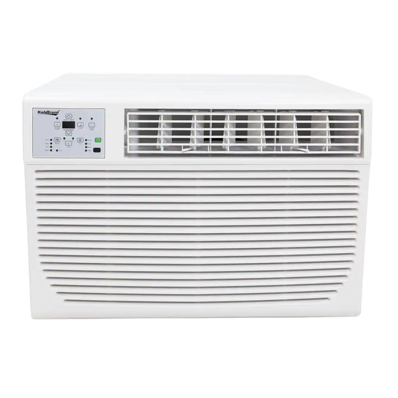
 SERVICE MANUAL Koldfront Window Air Conditioner with Supplemental Heat Function MODEL: WAC8001W WAC12001W WAC18001W WAC25001W CAUTION: READ ALL SAFETY PRECAUTIONS IN THIS MANUAL BEFORE SERVICING THE UNIT EdgeStar, 8606 Wall St, Suite 1800, Austin, TX 78754 support.edgestar.com •...
SAFETY PRECAUTIONS WARNING: This manual and the information contained herein is intended for use by certified technicians. The manufacturer or seller is not responsible for the interpretation or misuse of the information provided, nor does it assume any liability in connection with its use. The safeguards and warnings indicated in this manual do not cover all possible conditions which may occur.
Electrical Safety Do not exceed the power outlet ratings. It is recommended that the unit be connected to its own circuit. A standard electrical supply that is properly grounded in accordance with the National Electrical Code and all state and local codes and ordinances is required. ...
General Safety Always unplug an appliance from the power supply before attempting any service. Disconnect the power cord by grasping the plug, not the cord. Do not allow children or pets to play on or in the appliance. ...
1 Exploded Diagrams and Part Lists 1.1 WAC8001W and WAC12001W...
Page 7
Part Name Part Name Panel assembly 19.2 Top shutter frame Air filter 19.3 Right shutter assembly Remote control 19.3.1 Right shutter frame Electronic control box parts 19.3.2 Shutter Power cord 19.4 Screw bag Ambient temperature sensor assembly Condenser water tray Pipe temperature sensor assembly Evaporator coil parts Main control board assembly...
1.2 WAC18001W Part Name Part Name Front panel 20.4 Ambient temperature sensor assembly Air filter 20.5 Discharge temperature sensor assembly Panel frame parts 20.6 Power cord Panel frame 20.7 Main control board assembly 3.1.1 Air outlet assembly 20.8 Bracket for main control board 3.1.2 Horizontal louver 20.9...
Page 9
Part Name Part Name Condenser water tray Discharge pipe assembly Upper volute shell Super-cooling pipe Centrifugal fan Condenser assembly Front right barrier Chassis assembly Rear volute shell assembly Drain valve Asynchronous motor Cabinet assembly Rear separating Box for Electronic heater Axial flow fan Volute shell base Front cover...
1.3 WAC25001W Part Name Part Name Front panel 21.5 Capacitor for fan motor Air filter 21.6 Electronic control box Front panel and Panel frame parts 21.9 Room temperature sensor assembly Front panel and Panel frame assembly 21.10 Discharge/Heat sensor assembly Display box assembly 21.11 Defrost sensor assembly...
Page 11
Part Name Part Name Top shutter frame Front cover Chassis assembly Installation accessory Condenser assembly 31.1 Locking bar Cooling coil 31.2 Right bracket Discharge pipe 31.3 Shutter Evaporator assembly 31.4 Right shutter frame 18.1 Evaporator assembly 31.5 Connecting bar for cabinet 18.2 Capillary assembly 31.6...
3.3 Sensor and Display Connections on Main PCB All sensor connections are clearly marked on the PCB (Heat, Room, Def) and are located near the display ribbon cable connection. Refer to this diagram when troubleshooting unit display issues or sensor error codes.
4 Operating Instructions 4.1 Display Panel Controls On-Off Button Press to turn on or off the unit. NOTE: The Energy Saver feature will automatically turn on in Cool, Dry, and Auto mode. Up and Down Button Press or hold either Up or Down button until desired temperature is seen on the digital display.
Page 19
Timer Button button and the “Timer On” indicator light When the unit is on or off, press the Timer illuminates. It indicates that the Auto Start/Stop program is initiated. button again and the “Timer Off” indicator light illuminates. It To switch to off press the Timer indicates that the Auto Stop program is initiated.
4.2 Remote Controls The remote control has an operating range of 16 ft. from the appliance. The remote signal receiver/sensor is located on the control panel of the air conditioner. Reception of signal commands is confirmed by an audible beep. ...
5 Installation and Cleaning 5.1 Proper Installation and Drainage Older Koldfront window air conditioners included a drain plug that could be removed to assist with water drainage in excessively humid operating environments. Current models DO NOT use drain plugs. WAC series air conditioners were modified to increase unit operating efficiency and as a result the drain hole and plug have been removed.
5.2 Cleaning the Filter In order to maintain energy efficiency and prolong the life of the unit the air filter should be checked at least once a month to see if cleaning is necessary. In addition, trapped particles in the filter can quickly build up and cause frost on the evaporator.
6 Modes and Operating Conditions 6.1 Terms and Definitions TA: Temperature of indoor ambient. TE: Temperature of evaporator. TS: The set temperature. DAHT: Heater sensor. 6.2 Protection Functions The compressor restart protection has a delay of 3 minutes. ...
6.4 Fan-Only Mode If the temperature can’t be controlled by the selected mode and the room ambient temperature is shown on the display the unit will default to fan only mode. The readout can only display a temperature of 32 to 99 ℉ (0 to 37℃.) lf the temperature is out of that range the display will show LO or HI.
6.6 Auto-Defrost Function The Auto-defrost function operates according to the chart below: TE ℉ compressor on compressor off when TE is lower than 30 ℉ lasting for 5 seconds When TE is below 30℉ the evaporator will frost. As the unit defrosts the indoor fan will continue to operate.
6.8 Dry Mode In this mode, the air conditioner will operate as a dehumidifier. Because the conditioned space is closed or sealed, some degree of cooling will continue to occur. The dry mode temperature can be set from 62 to 86℉ (17 to 30℃.) ...
7 Troubleshooting Generally, problems are classified in three ways. The first is Starting Failure which is caused by an electrical defect. The second is an Air Conditioning failure caused by a defect in the refrigeration system or improper air circulation. The last is Structural Damage. 7.1 Troubleshooting Guide Problem Possible Cause...
Page 28
Problem Possible Cause Solution Clean air filter. Refer to Installation and Dirty air filter- air restricted. Cleaning section. Temperature is set too High. Set to a Lower temperature. The directional louvers on the Position louvers for better air distribution. front are positioned improperly. Air conditioner cooling, but room is too warm - Front of unit is blocked by...
7.2 Error Codes and Sensor Malfunctions Display Error Solution Room temperature sensor error.* 1) Check sensor connection to main PCB and Room sensor is an open circuit.* secure any detached or loose connections. Room sensor is a short circuit.* 2) Check sensor wire for damage and repair if possible.
Page 31
DATE REVISION NOTES 04/11/2018 INITIAL DOCUMENT EdgeStar, 8606 Wall St, Suite 1800, Austin, TX 78754 support.edgestar.com • service@edgestar.com • edgestar.com *Warranty service should be performed by an authorized service representative only.